Development of ATR-FTIR Kretschmann Spectroscopy for In situ Studies of Metal / Polymer Interfaces - and its Integration with EIS for Exposure to ...
←
→
Page content transcription
If your browser does not render page correctly, please read the page content below
Development of ATR-FTIR Kretschmann
  Spectroscopy for In situ Studies of
      Metal / Polymer Interfaces

  and its Integration with EIS for Exposure to
              Corrosive Conditions

                  Maria Öhman

                  Doctoral Thesis

              Stockholm, Sweden 2010

                   i
This doctoral thesis will with the permission of Kungliga Tekniska högskolan be
presented and defended at a public dissertation on 3rd of December 2010 at 10.00 in
lecture room F3, Kungliga Tekniska högskolan, Stockholm, Sweden.

Copyright © Maria Öhman, 2010

Paper I © Elsevier Ltd., 2006
Paper II © The Electrochemical Society, 2007
Paper III © Elsevier Ltd., 2007
Paper IV © Elsevier Ltd., 2010

Printed by AJ E-print AB
Stockholm, Sweden, 2010

TRITA CHE-Report 2010:47
ISBN 978-91-7415-782-6
ISSN 1654-1081

                                     ii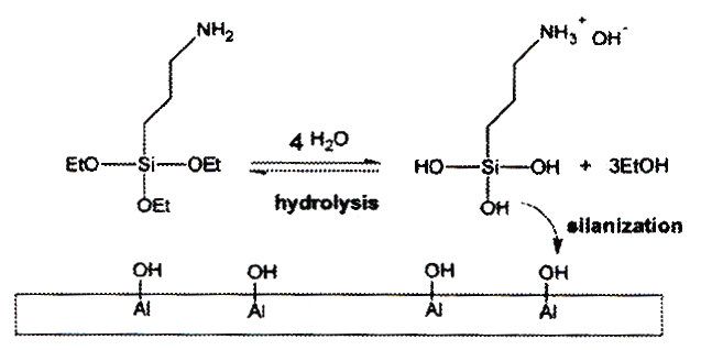
Abstract
The environmental stability of a metal / polymer interface is essential for the durability and
mechanical stability of constructions in several important areas such as the automotive, off-
shore, building and aerospace industries. The protective capability of a polymer film is
strongly connected to its barrier properties, but the transport of water and corrosive
constituents through the polymer and the subsequent processes at the metal surface are
complicated to analyse in detail. The surface to be analysed is confined between two media
that are impermeable to most probing particles used in conventional analytical techniques.
Several methods exist to describe separate parts of the system, but few techniques work at
ambient pressure and have the capacity to conduct real-time analysis at relevant exposure
conditions. In this work, attenuated total reflection Fourier transform infrared spectroscopy
(ATR-FTIR) in the Kretschmann geometry was successfully employed for systematic studies
of metal / polymer interfaces. This technique requires the use of thin metal films deposited on
an internal reflection element (IRE). Most studies were performed on aluminium, which is an
important structural light-weight material, but also zinc was analysed, being frequently used
for corrosion protection of steel. Upon exposure to water and electrolytes, the ATR-FTIR
Kretschmann technique was found capable to monitor and to separate early deterioration-
related processes at the aluminium / polymer interface, including water sorption and transport
of ionic species through the polymer film. Other main processes identified were the formation
of corrosion products and swelling of the surface-near polymer network. To perform more
comprehensive interpretations, a spectro-electrochemical method was further developed for in
situ studies of hidden metal / polymer interfaces. The ATR-FTIR Kretschmann technique was
combined with the complementary acting technique, Electrical Impedance Spectroscopy
(EIS). The integrated set-up was able to provide complementary information, with ATR-FTIR
Kretschmann being sensitive to the surface-near region and EIS to the whole system. For
instance, metal oxidation and delamination processes can be difficult to distinguish by EIS,
while on the other hand oxidation and hydration reactions on aluminium can be confirmed as
IR bands at distinct positions. Delamination and swelling of a polymer both result in negative
bands in an IR spectrum, but these processes may be distinguished by EIS as alterations in
different frequency regions. While traditional chemical pre-treatments for enhanced
hydrolytic stability perform excellent, they are being phased out from industrial applications
due to environmental concerns and work health issues. Today there is an intense ongoing
research regarding the mechanisms and performance of environmentally friendly pre-
treatments to develop systems of similar performance, and the analysis of the confined metal /
polymer interface is crucial for this development. The capability of the integrated in situ
ATR-FTIR Kretschmann and EIS set-up was therefore further applied to systems where a
surface pre-treatment had been applied to the metal prior to organic coating. Studies were
performed on vacuum-evaporated films of zinc treated with a titanium-based conversion
coating and coated with a UV-curing polymer. Alterations of the conversion layer could be
detected upon exposure to the electrolyte. Also alkaline-cleaned aluminium coated with an
amino-functional silane film and a thermo-curing epoxy top-coat was thoroughly
characterized by both ATR-FTIR and IRRAS, and further investigated upon exposure to
electrolyte and humid air. Changes at the hidden interface were detected upon thermal curing
of the epoxy film and during exposure in electrolyte, and the in situ ATR-FTIR Kretschmann
analysis showed a high sensitivity towards alterations in the interfacial region.
Complementary studies in the absence of metal could confirm a water uptake within the silane
film and water-induced alterations of the siloxane network.

                                       iii
List of Publications
I. In situ ATR-FTIR studies of the aluminium / polymer interface upon
exposure to water and electrolyte
Maria Öhman, Dan Persson and Christofer Leygraf
Progress in Organic Coatings, 57 (2006) 78-88
II. A spectro-electrochemical study of metal/polymer interfaces by simultaneous
in situ ATR-FTIR and EIS
Maria Öhman, Dan Persson and Christofer Leygraf
Electrochemical and Solid-State Letters, 10 (2007) C27-C30
III. An integrated in situ ATR-FTIR and EIS study of buried metal / polymer
interfaces exposed to an electrolyte solution
Maria Öhman and Dan Persson
Electrochimica Acta, 52 (2007) 5159-5171.
IV. In situ studies of conversion coated zinc / polymer surfaces during exposure to
corrosive conditions
Maria Öhman, Dan Persson and Dan Jacobsson
Accepted for publication in Progress in Organic Coatings
V. ATR-FTIR Kretschmann spectroscopy for interfacial studies of a hidden
aluminium surface coated with a silane film and epoxy.
I. Characterisation by IRRAS and ATR-FTIR
Maria Öhman and Dan Persson
Manuscript submitted to Surface and Interface Analysis
VI. ATR-FTIR Kretschmann spectroscopy for interfacial studies of a hidden
aluminium surface coated with a silane film and epoxy.
II. Analysis by Integrated ATR-FTIR / EIS during Exposure to Electrolyte
with Complementary Studies by in-situ ATR-FTIR and in-situ IRRAS
Maria Öhman and Dan Persson
Manuscript submitted to Surface and Interface Analysis
ivAuthor Contributions
The work was planned together with the supervisor Dan Persson and performed by the
author. The manuscripts were mainly written by the author in close co-operation with
the supervisor / co-author.
All experimental work was performed by the author, except for the coating-application in
Paper IV, the GDOES analyses in Papers IV and V, and the EDX analysis in Paper V. The
calculated spectra presented in Paper V were derived by the supervisor / co-author.
vContents
1. INTRODUCTION.........................................................................................1
1.1. BACKGROUND AND PURPOSE OF THE STUDY ..............................................1
1.2. OBJECTIVE .................................................................................................2
1.3. MATERIAL ASPECTS ...................................................................................3
1.3.1. Aluminium and zinc as construction materials .................................3
1.3.2. Novel chemical pre-treatments for aluminium and zinc ...................4
1.3.3. Transport through polymer films ......................................................7
1.3.4. Failure modes of the metal / polymer interface.................................8
1.4. ATR-FTIR KRETSCHMANN – THE MAIN METHODOLOGY ..........................9
1.4.1. Background of ATR-FTIR ................................................................9
1.4.2. The ATR-FTIR Kretschmann geometry .........................................12
1.4.3. Integrated in situ ATR-FTIR Kretschmann and EIS.......................15
2. EXPERIMENTAL ......................................................................................20
2.1. MATERIALS AND SAMPLE PREPARATION ..................................................20
2.2. EXPERIMENTAL TECHNIQUES ...................................................................21
2.2.1. ATR-FTIR Kretschmann.................................................................21
2.2.2. EIS ...................................................................................................22
2.2.3. IRRAS .............................................................................................22
2.2.4. Complementary FTIR analyses .......................................................23
2.2.5. EDX.................................................................................................23
2.2.6. GDOES............................................................................................23
2.2.7. Gravimetrical measurements...........................................................23
3. RESULTS AND DISCUSSION..................................................................24
3.1. INITIAL STUDIES BY IN-SITU ATR-FTIR KRETSCHMANN ........................24
3.2. IN SITU ATR-FTIR KRETSCHMANN STUDIES...........................................25
3.3. INTEGRATED IN SITU ATR-FTIR KRETSCHMANN AND EIS .....................28
3.3.1. Introductory examples using plain polymer-coated aluminium......28
3.3.2. Polymer-coated metal including a chemical pre-treatment.............36
4. CONCLUDING REMARKS......................................................................52
5. FUTURE WORK ........................................................................................53
6. ACKNOWLEDGEMENTS........................................................................54
7. REFERENCES ............................................................................................55
Papers I-VI
vi1. Introduction
1.1. Background and purpose of the study
The most common mechanisms for deterioration and structural failure of polymer-coated
metals and adhesively bonded metal structures are triggered by exposures to the surrounding
environment. This means that the stability of a metal / polymer interface is essential for the
durability and mechanical stability in several important areas such as the off-shore, building,
automotive and aerospace industries.
A major aim of applying an organic coating to a metal is to suppress electrochemical reactions
at the metal surface by excluding water and other corrosive constituents. Nevertheless, water
will move within a polymer film, either by diffusion through the bulk phase or by migration
through pores and other defects 1-7. This makes the analysis of the hidden interface of utmost
importance to secure the quality of the system. Despite great efforts made to understand the
interfacial stability of a metal / polymer system, there is still a lack of knowledge regarding
processes at the hidden interface and the mechanisms that destabilize the structures upon
exposure to corrosive conditions. A major reason for this lack of information is that the metal
/ polymer interfaces are confined between two media that are impermeable to probing
particles such as photons, electrons and ions. This means that the mechanisms of deterioration
as well as the inhibiting behaviour of protective surface films are very difficult to evaluate.
Analysis at the hidden metal / polymer interface is also crucial for the development of novel
environmentally friendly pre-treatments, where it is important to understand e.g. the nature of
bonding to the metal and interactions with the organic coating, as well as the water-induced
changes of the surface films and the role of corrosive constituents on the interfacial stability.
Methods exist for analysis of separate parts of these phenomena, but both the transport of
water and ions to a metal / polymer interface and the subsequent processes at the metal
surface are complicated to analyse in detail. Several electrochemical techniques have
considerably increased the understanding of the corrosion properties of metal / polymer
interfaces. Electrical impedance spectroscopy (EIS) 8-11 constitutes a powerful tool for in situ
monitoring of the transport of electrolyte in attached polymer films on metals, as well as of
corrosion and other processes at the metal surface. The scanning Kelvin probe can be used to
follow the water uptake during exposure to both water/electrolyte solutions and humid air,
and can also monitor corrosion processes and local electrode potentials at the metal surface
beneath the polymer film 12-15. In addition, scanning Kelvin probe force microscopy has been
used to investigate the mechanisms of delamination at a polymer-coated metal surface 16, 17.
Solid state nuclear magnetic resonance spectroscopy 18 and neutron reflectivity 19, 20 can be
used to map the presence and interactions of moisture in the metal / polymer interfacial
region. The transport of ions through polymers has also been analysed by molecular probe
techniques 21, 22, by quantitative electron probe microanalysis 23, and by using radioactive
electrolyte solutions 2, 23. Also adhesively bonded joint structures have been studied by
dielectric techniques that determine e.g. the quantity and state of water within the polymer
and identify hydroxide formation at the metal substrates 24, 25. However, there is a need for
additional chemical information from surface analytical techniques in order to unambiguously
1interpret the results. For instance x-ray photoelectron spectroscopy and time-of-flight
secondary-ion mass spectroscopy have been used together with an ultra-low-angle microtome
technique for composition depth profiling of attached polymer films 26. Cross-sections may
also be prepared for transmission electron microscopy 27, 28, which allows further elemental
analysis with e.g. energy dispersive x-ray spectroscopy. As the use of high-vacuum
techniques may cause alterations of the surface to be studied, the data obtained from an
analytical technique is more reliable when working at ambient pressure. The analytical
technique further benefits from the capacity to conduct in situ analysis at relevant exposure
conditions.28
One advantage with Fourier transform infrared spectroscopy (FTIR) over many other surface
analytical techniques is the possibility to follow corrosion processes in situ under climatic
conditions, both in humid air and in liquids. In the field of corrosion, FTIR is frequently used
to study the corrosion product formation and the degradation of organic coatings. Infrared
reflection absorption spectroscopy (IRRAS) is based on reflection of infrared radiation with a
grazing angle of incidence on the metal surface. Due to the enhancement of the electric field
strength perpendicular to the plane of the metal surface, IRRAS is highly surface sensitive
when using polarized IR radiation and permits the analysis of very thin surface films. IRRAS
may provide information about both the composition of the surface film and the bonding to
the metal surface and has for example been applied for in situ studies of atmospheric
corrosion 29-31. In the presence of very thin organic films, in situ FTIR micro-spectroscopy in
the external reflection mode has also been applied to study the mechanisms of filiform
corrosion beneath the organic film 32. While IRRAS is restricted to analysis of thin surface
films, the attenuated total reflection (ATR) FTIR, also known as internal reflection
spectroscopy, can be applied on thick films and opaque solutions 33-35. Furthermore, ATR-
FTIR in the Kretschmann geometry 33 allows surface studies of thin metal films deposited on
an infrared-transparent material, and is the technique on which this work is based.
1.2. Objective
Mechanisms of deterioration and the inhibiting behaviour of protective surface films are of
utmost importance but are very difficult to evaluate. This work seeks to investigate the
stability of a hidden metal / polymer interface and to extract chemical information of the
surface that is confined between two media. ATR-FTIR in the Kretschmann geometry has the
ability to detect alterations obtained from vibrations of IR-active species such as water,
polymers and certain corrosion products and ions. As the destabilisation of the interface is
promoted by the ingress of water and electrolytes, a more comprehensive picture may
however be obtained from combining the ATR-FTIR Kretschmann set-up with an
electrochemical technique, where electrochemical impedance spectroscopy (EIS) was chosen
for conducting integrated spectro-electrochemical studies upon exposure to electrolyte
solutions 36-39. Analysis at the hidden metal / polymer interface is also crucial for the
development of novel environmentally friendly pre-treatments, where it is essential to
understand issues as the nature of bonding to the metal, the interactions with the organic
coating, the water-induced changes of the surface films and the role of corrosive constituents
on the interfacial stability. The capability of the experimental set-up was therefore further
employed for analysis of metal / polymer systems where a surface pre-treatment was applied
to the metal prior to coating.
21.3. Material aspects
1.3.1. Aluminium and zinc as construction materials
This work is based on the technically interesting metals aluminium and zinc. Aluminium is a
low-density metal with good mechanical strength when alloyed. This makes it useful in a
wide range of applications for example in transport, building, aerospace and off-shore
applications. Today aluminium alloys are used as construction material for several car
components in the advancement of the light vehicle technology. The ductility of aluminium is,
on the other hand, beneficial in the flexible packaging industry, where untreated aluminium
foils are coated by thin organic films. When exposed to the atmosphere, a thin continuous
layer of aluminium oxide (Al2O3) is spontaneously formed at the surface. Normally, the oxide
film formed in air at ambient temperature is only about 2.5 nm thick. This passive film is
usually amorphous and immediately reforms when damaged. This makes untreated aluminium
alloys relatively well protected towards further corrosion, but upon environmental exposure
the formation of a weak boundary layer is considered detrimental for the interfacial stability
and the adhesion to organic coatings (Figure 1.1a) 26, 40-43. In order to improve the interfacial
stability, many applications require an additional chemical pre-treatment that interacts with
the metal surface prior to organic coating. Zinc is a commonly used material for corrosion
protection of steel by e.g. hot-dipped galvanizing (HDG) or electro galvanizing (EG)
processes. All mild steels and cast irons can be hot-dip galvanized, but the thickness and
structure of the coating will depend on the alloying elements. With steel and zinc in contact in
the presence of an electrolyte, a current will flow to the zinc. This makes zinc the anodic
electron-producing corroding area while the steel surface is protected 44. The native surface
film on zinc is however considered troublesome for further adhesion to an organic coating and
the zinc surface also easily form basic zinc carbonates at ambient atmosphere (Figure 1.1b).
In the presence of an aggressive environment, the zinc therefore requires further corrosion
protection, such as a chemical pre-treatment, prior to organic coating.
OH OH OH
--- Al2O3, AlOOH, Al(OH)3
OH OH OH
--- Al2O3 --- ZnO, Zn(OH)2
Zn5(OH)6CO3
--- Al --- Zn
(a) (b)
Figure 1.1. Schematic picture of surface films commonly formed at ambient
climatic conditions on (a) aluminium and (b) zinc.
The surface hydroxyl groups on various metal oxides are subjected to acid-base equilibria in
aqueous solutions. The isoelectric point (IEP) denotes the pH were the surfaces has no net
3charge. At a pH above the IEP, the surface has a net negative charge, while at a pH below the
IPE the surface charge is positive. The acid-base properties of the oxide surface are of
significance for the interaction of ionic and molecular species with the oxide surface, such as
the formation of silane layers on the surface and the interaction between this oxide and
functional groups in organic coatings. For oxidised/hydroxylated pure aluminium, the IEP is
about 8-10, but for aluminium alloys the IEP depends on the alloying elements and may be
significantly lower 45, 46 For zinc oxide the IEP is about 9 47.
The ATR-FTIR Kretschmann spectroscopy used as the main technique in this study requires
the use of thin metal films. For this reason, model substrates of pure aluminium and zinc were
produced by vacuum evaporation. Thin metal films deposited by evaporation may however
have densities, optical and electrical properties that significantly differ from those of the bulk
metal 34, 48-50.
1.3.2. Novel chemical pre-treatments for aluminium and zinc
Organic coatings are commonly applied on both aluminium and HDG/EG steel for example in
order to extend their applications by an improved corrosion resistance, for aesthetic surface
finish purposes, and on for aluminium to improve its food compatibility in the packaging
industry. Additionally, the interest in adhesively bonded structures is increasing, e.g. in the
advancement of the light vehicle technology. Although organic coatings may provide a rather
good protection, the system is not perfect. A common method to improve the hydrolytic
stability of organically coated metals is to apply a chemical pre-treatment on the metal
surface.
The protective properties of traditional chromium conversion coatings are superior to those of
other surface treatments, with dense oxides working as a barrier towards corrosive
constituents and as a repository for soluble hexavalent chromium that can be released, diffuse
to a corroding site and form a passivating oxide. However, the use of hexavalent chromium is
legally restricted due to its harmful effects on human health and the environment and is being
phased out from industrial applications. Huge efforts are made to develop “green” inhibitors
to provide interfaces of similar stability. Phosphating of aluminium and zinc provides hard,
crystalline, insoluble oxides and phosphates of the metal being treated. The corrosion
protection comes from the insulating nature which prevents onset and spreading of corrosion.
However, also the phosphating process experiences criticism due to its environmental impact
and high costs of waste treatment.
Conversion coatings with a low environmental impact may be based on for instance
zirconates and titanates, which form transparent colourless films by interfacial precipitation of
metal oxides and hydroxides 27, 51. An oxide layer is formed by oxides of the base material
mixed with precipitates of TiO2 and/or ZrO2. The amount and distribution of oxide on the
surface depends on the alloy composition and the electrochemical heterogeneity 51-53. The
deposition mechanisms have for example been studied by scanning Kelvin probe force
microscopy 52 and energy dispersive x-ray spectroscopy 52, 54. The composition of the thin
films may be studied by x-ray photoelectron spectroscopy 51, 55-57 and glow-discharge optical
emission spectroscopy 51, 54, while thin film morphology also have been studied by e.g.
spectroscopic and visual ellipsometry 58, neutron reflectivity 59 and electron probe
microanalysis 27. Figure 1.2 exemplifies the appearance of such conversion-coated films, first
with a transmission electron micrograph of aluminium AA 6060 treated with a Ti-Zr-based
4conversion solution (with preferred deposition on cathodic inclusions such as α-AlFeSi 27, 51)
and also two FEG-SEM micrographs of a HDG-steel surface, as-received and after treatment
with a Ti-based conversion solution, respectively 60.
(a) (b)
Figure 1.2. (a) Transmission electron micrograph (cross-section) of
aluminium alloy AA6060 treated with a Ti-Zr-based conversion solution 27,
51
and (b) FEG-SEM micrographs of HDG-steel as-received and after
treatment with a Ti-based conversion solution 60.
The insulating properties and mechanisms have been investigated by for example
electrochemical impedance spectroscopy 15, 61, 62 and scanning Kelvin probe 15. In order to
obtain better corrosion-resistant properties, some systems also contain organic components
which act as complexing agents for the inorganic components and also protect by forming a
barrier layer 56. While many studies of chromium-free conversion coatings exist on aluminium
substrates, fewer studies have been performed on zinc or zinc-plated steel 57, 60, 63. In the
present study (Chapter 3.3.2); an aqueous conversion system based on hexafluorotitanic acid
is applied on zinc substrates.
Another environmentally acceptable route is to apply adhesion promotors such as silanes to
the metal substrate. Organofunctional silanes received attention in the 1940’s, as coupling
agents for improving the adhesion between glass fibers and their organic resins 64, 65, and they
were soon also considered for metal substrates. In contrast to the case with conversion
systems, the metal does not participate electrochemically in the film deposition mechanism.
Instead the silane forms an interfacial layer of covalent bridges at the interface between the
alkali-cleaned metal substrate and an organic coating. The silanol groups (Si-OH) of a
hydrolysed organosilane have a pH of ~2-3 and are relatively stable in acid solutions. When
the pH in the solution is lower than the IEP value of the metal, these negatively charged Si-
OH groups may coordinate with metal hydroxyl groups present at the metal surface (Figure
1.3). Residual silanols form a densely cross-linked siloxane multilayer that is aimed to
provide further protection against hydration and the action of aggressive species. The amino-
functionalities react further with the functional groups of the organic coating.
5Figure 1.3. A schematic picture of silane-reactions at a metal surface,
with hydrolysis of the amino-functional organosilane and subsequent
condensation of the silanols at a hydroxylated aluminium surface 66.
The mechanism of adhesion is not well understood, and is difficult to verify by analytical
tools. For aluminium substrates, the Al-O-Si+ structure has been suggested from secondary-
ion mass spectroscopy studies 67, 68. Adsorption of silane to metal has also been verified by x-
ray photoelectron spectroscopy 69. However, while several FTIR studies have claimed the
presence of Al-O-Si linkages, these studies 70-74 may be less convincing as the spectral region
assigned to possible Al-O-Si linkages strongly overlaps with vibrations related to Si-O and
Al-O. These studies also say little regarding film coverage and coating weight. Thin film
thicknesses have been deduced by e.g. spectroscopic ellipsometry 28, 75-77, Auger electron
spectroscopy 28 and transmission electron microscopy 28. Adhesion to a polymer top-coat may
be the result of both physical interactions and chemical bonding through a functional end
group. Due to regulations and restrictions regarding the use of solvents for industrial
applications, commercial products today are commonly delivered as water-based pre-
hydrolysed solutions. The corrosion resistance of a silane layer may be rather poor in itself,
especially for more hydrophilic films, and it is important to obtain a film of low porosity 77-79.
Also mixtures of different types of silanes may be more effective than a single silane 80.
Several manufacturers currently also combine silanes with inorganic components and organic
additives within the same product, and studies are ongoing regarding the use of active
inhibiting components such as cerium and zirconium nitrates 81 and nanoparticles of cerium
oxide 82. In the present study (Chapter 3.3.2); a water-based mixture of two different silanes is
deposited onto alkali-cleaned aluminium substrates.
61.3.3. Transport through polymer films
Water and other species will move within a polymer film, either by capillary flow (non-
activated diffusion) through pores and irregularities, or through the polymer bulk phase by
means of activated diffusion through holes formed as a result of segmental motion of the
polymer network 1-7, 41, 83-88. The polymer film also acts like an ohmic barrier between the
anodic and cathodic sites 1, 3, 6, 84-86, 88, 89 and the electrolytic resistance is determined by its
dielectric properties.
The main sorption modes of water within a polymer network are bulk dissolution, clustering
of water molecules, hydrogen-bonding to hydrophilic groups in the polymer, and adsorption
onto free volume micro-voids 90-92. At low water activities, water enters spaces that already
exist in the molecular structure, and interact with polar or ionic groups in the network. At
increased water activity, accumulation of water can result in an elastic stretching 6. Water
molecules within a polymer network are generally more weakly hydrogen-bonded than in a
pure water network 93. Due to the high degree of defects introduced in the water structure,
interstitial water also appears differently from bulk water in an IR spectrum 93-97.
The processes and properties that affect the polymer permeability and susceptibility to ageing
are strongly dependent on the structural and chemical properties of the polymer. The
solubility of water, the degree of swelling and the mode of relaxation are influenced by for
instance the exposure time, the degree of hydrophilicity of the polymer, and the porosity of
the polymer matrix 6, 90, 98, 99. Additional factors are the curing conditions, the surrounding
temperature, partial pressure and the properties of the penetrant 6, 85, 100, 101.
For a polymer bulk phase, the flux of matter, J, through a polymer film can be expressed by
Fick’s first law of diffusion in terms of the concentration gradient and the diffusion
coefficient, D, of the penetrating medium (Eq. 1) 102.
dc
J = −D (Eq. 1)
dz
For a free homogenous film of insignificant swelling, the mass uptake as a function of time
may be fit to a single Fickean diffusion coefficient. The mass transport of the penetrating
medium can then be given by Eq. 2, where L is the sample thickness and Mt and M∞ represent
the mass of water at time t and at equilibrium, respectively 103, 104.
− D ( 2 n +1)2 π 2t
∞
Mt 8
= 1− ∑
4 L2
⋅ e
(Eq. 2)
n = 0 (2n + 1) π
2 2
M∞
The mass uptake is frequently plotted against the square root of exposure time, and the so
called Fickean diffusion profile is initially linear with a well defined equilibrium level. In the
presence of swelling, the diffusion has rather been found to be a linear function of time 105, 106
and also fracturing of the material is common 106. This method does however not provide any
information about solution constituents accumulated at the interface of an organically coated
metal. A free film can also swell freely, while an attached adhesive brings about restrictions in
7motion. Depending on the polymer used, the water uptake will be greater in either a free or an
attached film. An increased water uptake in a free film has been assigned to its lack of
rigidity, which means that distortions due to water penetration occur much faster 6, 107, 108. A
greater transport through an attached film, although restricted in swelling, has been explained
by a higher degree of capillary diffusion and by the possibility of accumulation at the
interface 108, 109. A poor adhesion may result in a faster water transport along the interface 110.
The presence of an electrolyte affects the water activity and leads to a decreased water uptake
as compared to deionised water 102. Different theories exist concerning the transport of
electrolytes through polymer films, e.g. that negatively charged pore walls act as selectively
permeable membranes towards cations 1-5, or that cations rather are impeded due to their
electrostatic attraction to these pore walls 6, 7. There is a close relationship between the
electrolytic resistance and the protective ability of the coating 7, 85, 111. Localized areas of
different types of conductive behaviour have also been identified within one single polymer
film 3.
1.3.4. Failure modes of the metal / polymer interface
The penetration of water and electrolyte through a polymer allows the formation of a
corrosive environment and is detrimental for the metal / polymer interface. Although strong
hydrogen-bonding contributes to the adhesion of a polymer film to the metal surface, the
adhesion is to a large extent due to weaker physical interactions such as van der Waals forces,
which are easily replaced by more stable bonds formed between the oxide and water 26, 41-43.
Delamination may also occur as a result of a specific corrosion process. One common
mechanism for loss of coating adhesion on aluminium is anodic undermining, where loss of
adhesion is obtained at low pH through anodic dissolution of aluminium or the aluminium
oxide film. Anodic undermining is also suggested to be the most probable mechanism for
filiform corrosion on coated aluminium 112. Cathodic delamination is a common failure mode
of coated steel and zinc and is caused by alkalinity at the interface as a result of cathodic
activity underneath the coating 87, 111. If the transport of water along the interface is hindered
by corrosion product formation, or by strong adhesive bonds, localized blistering will occur
rather than delamination 84. Cathodic blister formation occurs in alkaline environments and in
the vicinity of defects or conductive pathways 87, 113, while anodic blistering demands a low
pH to proceed 87. Osmotic phenomena such as osmotic blister formation and accumulation of
water at the interface may also result from the presence of corrosion products at the metal
surface and from hydrophilic material present due to contamination 84, 114. Additionally,
interfacial water along the interface can mechanically affect the blistered or delaminated film.
Apart from promoting corrosion and deterioration at the metal / polymer interface, the
penetrating medium may also cause alterations of the polymer film itself 6, 7, 86, 115. Phenomena
such as plasticization and swelling may be reversible, but may also lead to irreversible
processes such as cracking, crazing or hydrolysis. The polymer can also be subjected to
degradation by aggressive reaction products. With a proceeding polymer breakdown, regions
of electrolytic conductivity will exist randomly over the surface. Paths of complete
penetration allow the electrolyte to meet the metal oxide interface and a corrosion cell is
activated 7, 111.
81.4. ATR-FTIR Kretschmann – The main methodology
1.4.1. Background of ATR-FTIR
Fourier transform infrared spectroscopy (FTIR) monitors the interaction between an
electromagnetic field and a molecule as it undergoes a net change in dipole moment as a
result of a vibrational or rotational motion. Molecular species that may obtain such a net
change in dipolar moment will absorb infrared radiation at a frequency that exactly matches a
frequency of molecular motion. When analysing an organic film, the technique may
distinguish between the organic compounds and solutes within the film and measure the
chemical interactions through shifts in band-positions in the IR spectrum. FTIR can be
employed in different modes, but attenuated total reflection FTIR (ATR-FTIR) has the
advantage of being applicable to thick films and opaque solutions 33-35. ATR-FTIR is based on
total reflection of the incident IR radiation at the surface of an internal reflection element
(IRE). Total reflection occurs for angles of incidence of the radiation greater than a certain
critical angle, θc, which is determined by Snell’s law (Eq. 3),
n2
θ c = sin − 1
(Eq. 3)
n1
where n1 and n2 are the refractive indices of the IRE and of the sample, respectively. At the
point of incidence, incoming and reflected radiation are superimposed to form a standing
wave perpendicular to the surface of the denser medium, all in accordance with the field-
matching boundary conditions imposed by the Maxwell equations 33, 116. The amplitude and
phase change of this electromagnetic standing wave will depend on the direction of the
electrical vector of the wave front. This is divided into two components in the incident plane,
one tangential to the surface and one normal to the incident plane. When polarized radiation is
used, the perpendicular polarized radiation only obtains a tangential component (Ey). The
light polarized parallel to the plane of incidence becomes elliptically polarized at the surface
and obtains electric field components both tangential (Ex) and normal (Ez) to the surface. In
the case of total reflection there is no net flow of energy transmitted across the IRE surface.
However, a requirement for the standing wave, in order to fulfil certain boundary conditions
in accordance with the Fresnel equations116, is that the periodicity of the electromagnetic field
in time and space is equal at both sides of the IRE surface. While the two tangential
components, Ex and Ey, are continuous across the IRE surface, the normal component, Ez,
shows a discontinuity. For fulfilling of the boundary conditions, this Ez component will
experience a magnification of its electric field strength at the interface, a so called “field-
matching” 33. This results in an evanescent field that passes into any optically less dense
medium held in contact with the IRE 33, 116. This evanescent field, with vector components in
all spatial directions, holds an electric field amplitude, E0, that decays exponentially with
increasing distance from the IRE surface 117. Figure 1.4 shows a schematic picture of the set-
up described, with θ as the angle of incidence of the incoming infrared radiation, n1 as the
refractive index of the IRE and n2 as the refractive index of the optically less dense medium.
9IR-radiation θ
IRE = n1
E0
dp n2
-z/dp
E0*e
z
Evanescent wave
Figure 1.4. The standing wave amplitude characteristics in the
vicinity of a totally reflecting interface, with the sinusoidal
electric field amplitude in the IRE, n1, and the exponentially
decaying amplitude in the optically less dense medium, n2 117.
When the optically less dense medium possesses an absorbing character and holds a complex
refraction index ñ = n – i·k, where k is the attenuation index, the evanescent field will be
accompanied by an irreversible loss of energy. This means that the total internally reflected
radiation is attenuated (reduced), while it results in a characteristic spectrum of the absorbing
medium.
According to Harrick 33, the depth of penetration, dp, of this evanescent field is defined as the
distance from the IRE where the electric field amplitude has decreased to 1/e of its value at
the surface. For a non-absorbing interface, dp can be calculated according to Eq. 4,
λ
dp = 0.5
(Eq. 4)
n
2
2πn1 sin 2 θ − 2
n1
where λ is the wavelength of the radiation 33. This wavelength-dependence means that
absorption bands at longer wavelengths (shorter wavenumbers) are relatively more intense
than those at shorter wavelengths (higher wavenumbers).
If the IRE is coated with a polymer film prior to exposure to a penetrant, then any medium
transported through the film will interact with the evanescent field within its depth of
penetration and the components that are subjected to a change in its dipole moment will be
detected. For a ZnSe element (n1 = 2.42) covered with a polymer film and radiation incident
at 75°, and by assuming the polymer and the penetrant medium to have a constant refraction
index of n2 = 1.5, the value of dp within the spectral region of interest would range from ~ 0.2
to 1.4 µm (4000-600 cm-1).
104000 – 600 cm-1
75° n1 =2.42
0.2-1.4 µm n2 ~ 1.5
Figure 1.5. The ATR-FTIR set-up with an estimated depth
of penetration using parameters of relevance for the
present study.
The effective thickness, de, is on the other hand defined as the actual strength of interaction of
the evanescent wave with the sample, and represents the actual sample thickness that would
be required to obtain the same absorption in a conventional FTIR transmission spectrum 33, 118,
119
. For small absorptions, the value of de may be approximated as described in Eq. 5 119 with
the parameters defined according to Figure 1.4.
n2 n2
∞ − z
n1 n d
∫ cosθ ∫
p
de = E 2 dz = E0 ⋅ e
1
dz (Eq. 5)
cosθ q
This means that de depends on the depth of penetration, dp, the angle of incident radiation, and
the refractive indices of the materials, as well as on the electric field strength, E0, in the rare
medium. When the thickness of the second medium is much greater than dp, the value of de is
calculated according to Eq. 6 119.
n2 n2 2
∞ E0 d p
n1 n1
cos θ ∫q
de = E dz =
2
(Eq. 6)
2 cos θ
As the imaginary refractive index still is assumed to be zero, also these equations are based on
non-absorbing media. This type of ATR-FTIR investigations have been performed on the
transport of water and other species through a polymer film to substrates made from various
IRE-materials 33, 99, 101, 120-124. The use of an infrared active ion has also made it possible to
detect ionic species at the IRE / polymer interface 125. The analyses also provide valuable
information regarding time-dependence and mechanisms of transport processes.
11In order to obtain time-resolved diffusion data of relevance for an attached polymer film, the
polymer can be coated directly onto the ZnSe IRE and exposed to the electrolyte. This makes
it possible to extract the diffusion coefficient of water, D, using the relation between Fick’s
first law of diffusion (Eq. 1) 103 and the ATR-FTIR absorption intensity of the water vibration
band with time as deduced by Fieldson and Barbari 104. For a homogenous film with neglected
swelling, this relation constitutes an analogue to Eq. 2 and can be simplified as:
− Dπ 2t −2 L
π dp 2
⋅ ⋅e
+
2
8 e 4L
2L d p
At dp
= 1− ⋅ (Eq. 7)
A∞
−2 L
4 π
2
d +
π 1 − e p
d 2 2L
p
At and A∞ are the absorbance at the time t and at saturation, L is the thickness of the polymer
film, and dp is the depth of penetration of the IR radiation as defined by Harrick 33. This
relationship is only valid for the polymer in direct contact with the IRE.
1.4.2. The ATR-FTIR Kretschmann geometry
While conventional ATR-FTIR analyses provide information about kinetics and mechanisms
of transport processes, the results are not representative for more technically interesting
surfaces such as metals. However, despite the strongly absorbing character of metals, an
electric field can still pass through a thin metal film of tens of nanometers deposited onto an
IRE. This is the so called ATR-FTIR Kretschmann geometry 126. If the thin metal film is
subsequently coated with a polymer film, the transport of species to the interface as well as
changes in the metal / polymer interfacial region can be studied. Figure 1.6 shows a schematic
picture of the set-up used for the surface-near analysis of the hidden interface between an
aluminium film and a polymer.
ZnSe
Metal
Hidden interface
Polymer
Penetrating media
Figure 1.6. The hidden interface between an
aluminium surface and a polymer film upon exposure
to penetrating media.
12As previously mentioned, the equations for extracting dp and de (Eqs. 4 and 6) are based on
non-absorbing media and can not be used for the systems including a thin metal film. While
the resulting magnitude of the absorption bands is strongly related to the thickness and optical
properties of the absorbing metal film applied to the IRE, the value of dp (Eq. 4) is actually
independent of the field strength; hence of the presence of a strongly absorbing metal film 127,
128
. The electric field amplitude value at the metal surface (E0, Metal) will however be different
from its value at the surface of a pure IRE (E0), and will vary depending on the metal film-
thickness. This means that there exists a practical limit in how thick the metal film may be
while still allowing analysis with the ATR-FTIR Kretschmann geometry within the detection
limits (Figure 1.7).
ZnSe ZnSe
E0 E0
E0, Metal
0.2-1.4 µm
(a) (b)
Figure 1.7. (a) The ATR-FTIR set-up with an estimated depth of
penetration and (b) the corresponding set-up of the ATR-FTIR
Kretschmann geometry.
Some authors 118 have suggested an estimation of de for the case of an absorbing second
medium by deriving a value of dp (Eq. 4) with the imaginary parts of the refractive index
included in the equation. This however results in a rather rough approximation of the physical
process, with a different definition of de which now becomes dependant on concentration 118.
This kind of calculation is not employed in the present study, where ATR-FTIR Kretschmann
is used as the main analytical tool for studies of the metal / polymer interfacial region upon
exposure to corrosive conditions. Some corrosion-related studies have previously been
performed by other authors using this technique, for example electrochemical reactions on
iron 129. On the other hand, studies of metal / polymer systems are more rare. Some authors
detected water at different iron / polymer interfaces 14, 105, 130, 131 and also corrosion was
observed 130.
In order to support data interpretation, calculated spectra may be derived from the Fresnel
equations 116, based on optical constants of each material as a function of the wavenumber and
on the phase shift of the electrical field as it crosses each interface 116, 132, 133. The reflected
and transmitted light intensities for e.g. p-polarised radiation can be calculated at each
interface using the matrix method for a stratified medium assuming plane parallel layers of
homogeneous media with known refractive indices. The calculated reflection and
transmission coefficients relate the electrical field strengths at each interface to the actual
reflectance and transmittance of the whole stratified system. For instance, a program has
13previously been developed at Swerea KIMAB AB that can be used for simulations of both
IRRAS and ATR-FTIR Kretschmann spectra 133.
The dependence on the resulting IR absorption intensity of the metal film-thickness was
investigated for the ATR-FTIR Kretschmann set-up by using thin films of gold exposed to de-
ionised water. As gold is an inert metal, it can be concluded that all contributions to the IR
spectrum are from water molecules only. Figure 1.8 displays the ATR-FTIR Kretschmann
spectrum of water in contact with a gold-coated ZnSe IRE, together with the ATR-FTIR
spectrum of water in contact with pure ZnSe 133.
3370
Absorbance, -log(R/R0)
0,015 ~3370 0,15
Absorbance, -log(R/R0)
3240
0,010 0,10As previously mentioned, thin metal films made from vacuum deposition have densities and
optical and electrical properties that significantly differ from those of the bulk metal. These
films may more resemble an array of dispersed islands 34, 48-50. This means that information
about the real and imaginary parts of the film dielectric constant and about the energy loss
function are required for an accurate interpretation of the structural features 34.
In the presence of a metal film with a thickness below ~10-20 nm, an enhanced signal-
strength of the ATR-FTIR absorption bands has been reported by several authors 117, 134-137.
This phenomenon was initially observed by Hartstein et al. 138 for evaporated over- and under-
layers of silver and gold, and has been referred to as surface enhanced ATR (SEIRA-ATR).
The dominant factor for this enhancement effect is believed to be an enhanced localized
electromagnetic field developed around the small particles that comprise the thin metal films.
Contributions to the enhanced field are also likely to occur from chemical effects, such as
charge-transfer interactions between adsorbate and metal. While the metal thicknesses used in
the present work probably exceed the thickness of relevance for these phenomena, it should
however be mentioned that such effects are not accounted for in the mathematically simulated
spectra.
1.4.3. Integrated in situ ATR-FTIR Kretschmann and EIS
In this work, a spectro-electrochemical set-up was introduced that enables in situ ATR-FTIR
Kretschmann measurements of polymer-coated metal substrates in combination with electrical
impedance spectroscopy (EIS).
Spectro-electrochemical ATR-FTIR in the Kretschman geometry has previously been
performed on uncoated metal surfaces for studies of adsorption 139-142 and film formation
under controlled potential 129, 143. Nguyen et. al 105 also studied water transport to an iron /
polymer interface under potentiostatic conditions. To the author’s knowledge, no studies on
polymer-coated metals have simultaneously combined any in situ FTIR technique with
electrochemical impedance measurements. Recently, Vlasak et. al. however presented a study
using combined ATR-FTIR and EIS for a polymer-coated semiconducting IRE made from
silicon 144.
EIS is a conventional AC technique, commonly used for in-situ monitoring of water transport
in attached polymer films on metal and constitutes a powerful tool for investigating
deterioration and corrosion. The basis for determining water uptake by EIS is by modelling of
the polymer film as the dielectric part of a capacitor. The impedance, Z, is used to measure
the system capacity to resist the flow of an alternating electrical current. Compared to DC-
techniques, EIS uses very small signals which do not disturb the electrode properties
measured, and it is possible to use low conductivity media.
A physical model of the investigated process may be described by an equivalent circuit of
electrical elements (resistors and capacitors) and other elements representing transport
phenomena 115. Figure 1.10(a) displays the electrochemical response of an intact polymer film
in contact with an electrolyte. This may be described as a purely capacitive element of the
polymer (CP) in series with an electrolytic resistance of the solution (RE). Figure 1.10(b)
shows the electrochemical response of a metal coated with a permeable film. When a resistive
part (RP) is introduced within the polymer film, any resulting process at the metal surface
must be taken into account and the circuit has to be extended. The element B may for instance
15symbolize a double-layer capacitance at the electrode surface, or a charge transfer resistance
involved in for example a corrosion reaction, or a diffusion element for situations were the
electrochemical reaction is limited by material transport 9, 10, 145.
RE WE
RE WE
Electrolyte Polymer Metal
Electrolyte Polymer Metal
Metal oxides / hydroxides
and surface pre-treatments
RE WE RE CP WE
RE CP RE B
RP
(a) (b)
Figure 1.10. Schematic electrochemical characteristics of a polymer-
coated metal with (a) an intact film and (b) a permeable film. The
electrical circuits constitute a reference electrode (RE) and a working
electrode (WE).
The measured response may be transformed from a time function into the frequency domain
using Laplace transformations. The electrochemical response displayed as impedance
relationships may then be presented as Bode plots with either the modulus of
impedance,│Z│, or the phase angle, defined as tan δ = Z’’/ Z’, versus log frequency. The
frequency-dependence of the phase angle accounts for the time shift between the current and
voltage sine waves and clearly indicates the presence of different time constants 9. The results
may also be displayed as a Nyquist plot, with the real impedance versus the imaginary
impedance in the complex plane (Figure 1.11). Data interpretation can be performed by
fitting of the impedance data to an equivalent electrical circuit, but often more than one circuit
exist to describe the same response. This makes it difficult to interpret the response in terms
of chemical and physical parameters 115. Due to the overlapping of time constants it is very
difficult to derive a transfer function of the reaction mechanisms for polymer coated metals.
16log│Z│ δ Z’’
Z’
log f log f
(a)
I
log│Z│ δ Z’’
Z’
log f log f
II
log│Z│ δ Z’’
log f log f Z’
(b)
Figure 1.11. Schematic electrochemical response of a polymer-
coated metal displayed as Bode impedance, Bode phase angle
and Nyquist plots for (a) an intact polymer film and (b) a
permeable film with (I) and without (II) ongoing surface
reactions.
Dipolar properties can be studied at high frequencies, while bulk properties generally can be
studied at intermediate frequencies and surface properties at low frequencies. However, at
longer exposure times these assumptions are not valid. For a polymer-coated metal, the
properties of the polymer film at shorter exposure times can often be associated with the
frequency region ~103 – 105 Hz, while the frequency region < 1 Hz provides information on
interfacial changes.
During the initial part of the exposure, the water content in an intact polymer film can be
estimated from impedance data by assuming the system to act as a purely plane-parallel
capacitor, thus with the modulus of impedance proportional to the coating capacitance at the
time t, Cp,(t),
17ε ⋅ε0 ⋅ A
C P (t ) = (Eq. 8)
L
where ε is the relative dielectric constant, ε0 is the dielectric permittivity of vacuum, A is the
sample area and L is the coating thickness. By assuming a uniform water distribution in the
polymer film and no polymer swelling (Fickean diffusion process), the diffusion of water can
be translated to a water volume fraction, φt, using the mixing rule of Brasher and Kingsbury
(Eq. 9), where εw is the dielectric constant of water at 20 °C and is set to 80 146.
C (t )
log P
ϕ (t ) = CP (t0 ) (Eq. 9)
log ε w
At short exposure times, before contributions from surface processes become relevant, the
diffusion coefficient for a polymer coating applied to a substrate may be estimated from the
reduced water volume fraction, φ(t)/φ(t∞) (Eq. 10), where C∞ is the capacitance at saturation
147
.
ϕ (t0 ) C (t ) − C (t0 ) 4 D ⋅t
= = (Eq. 10)
ϕ (t∞ ) C (t∞ ) − C (t0 ) (2 ⋅ L) π
18Figure 1.12 displays the experimental set-up based on combined ATR-FTIR Kretschmann and
EIS.
ZnSe ---
--- Metal
Polymer-- (Working Electrode)
Electrolyte---
Counter
Electrode
Reference
Electrode
Figure 1.12. Schematic view of the exposure cell
for combined ATR-FTIR Kretschmann and EIS.
192. Experimental
2.1. Materials and sample preparation
Thin metal films were deposited onto IRE hemispheres made from ZnSe (Harrick Scientific
Products Inc.) by high-vacuum evaporation of aluminium (99.9% pure, Ernest F. Fullam Inc.),
zinc (99.9 % pure, Goodfellow) and gold (99.95 % pure, Goodfellow). The vacuum
evaporators used were a JEE-4X/B (JEOL Ltd) (Papers I-III) and a Univex 300 (Leybold
Vacuum) (Papers IV-VI), respectively. The aluminium film thicknesses were determined by
inductively coupled plasma - atomic absorption spectrometry after dissolving the aluminium
in a weak solution of hydrochloric acid (performed by ALS Laboratory Group, Luleå,
Sweden). Evaporations performed by the Univex 300 were performed at an initial vacuum of
< 2*10-5 mbar, and allowed an estimation of the metal film thickness using an in situ quartz
crystal microbalance. The films produced by the older JEE-4X/B may have been of a higher
porosity and higher oxide content, thus possibly allowing a higher absorption intensity
compared to the thickness applied. The ZnSe IRE hemispheres were regenerated by
dissolving the aluminium and zinc in weak HCl and dissolving the plain polymer films in
dichloromethane. The gold and structural polymer coatings were removed by grinding and
polishing to a surface roughness of ~1 µm.
In Papers I-III the simple model systems used were all manually casted onto the metal-coated
ZnSe IRE. The polymers used were a transparent, one component, adhesive based on nitrile
rubber and a vinylchloride-vinylacetate co-polymer (Bostik 1782, Bostik Findley AB), a
transparent alkyd varnish (Syntoflex Klarlack, Becker Industrifärg AB), a pigmented two-
component epoxy adhesive (Auto marine epoxy +300, JB Weld) and a pigmented acrylic-
based sealant (Rubson Easy Fix, Henkel), respectively.
In Papers IV-VI, a pre-treatment was applied to the metal-coated IRE prior to coating with a
polymer. In Paper IV, the evaporated zinc surface was converted by spray application of a 10
% (pH 3) aqueous solution based on hexafluorotitanic acid, manganese salts, phosphoric acid
and organic components (Henkel KGaA). A titanium content of 8-18 mg/m2 was verified by
X-ray fluorescence (performed at Högskolan Dalarna, Sweden). A UV-curing polymer film,
based on a modified epoxy acrylate, was cast manually on top of the zinc conversion layer
and was cured under an Oriel UV-lamp at 0.55 J/cm2. In Papers V and VI a water-based silane
mixture was used based on pre-hydrolysed γ-aminopropylsilane (γ-APS) and bis[3-
triethoxysilylpropyl)]ethane (BTSE) (Chemetall GmbH) (Figure 2.1).
(a) (b)
Figure 2.1. The chemical formulae of pre-hydrolysed (a) γ-APS and (b) BTSE.
In order to promote the hydrolysis of BTSE and prevent pre-condensation reactions, the silane
system was purchased pH-adjusted with acetic acid. The deposition of silane was performed
20You can also read