Effective ion pathways and 3D conductive carbon networks in bentonite host enable stable and high-rate lithium-sulfur batteries
←
→
Page content transcription
If your browser does not render page correctly, please read the page content below
Nanotechnology Reviews 2021; 10: 20–33
Research Article
Lian Wu, Yongqiang Dai, Wei Zeng, Jintao Huang, Bing Liao, and Hao Pang*
Effective ion pathways and 3D conductive carbon
networks in bentonite host enable stable and
high-rate lithium–sulfur batteries
https://doi.org/10.1515/ntrev-2021-0005
received January 26, 2021; accepted February 5, 2021
1 Introduction
Abstract: Fast charge transfer and lithium-ion transport With the increasing energy demands of portable electronic
in the electrodes are necessary for high performance Li–S devices, electric vehicles, and grid storage, the develop-
batteries. Herein, a N-doped carbon-coated intercalated- ment of novel reliable battery systems with high energy
bentonite (Bent@C) with interlamellar ion path and 3D density is of great significance. Among the existing che-
conductive network architecture is designed to improve mical battery systems, lithium-ion batteries have attracted
the performance of Li–S batteries by expediting ion/ worldwide attention due to the advantages of high voltage,
electron transport in the cathode. The interlamellar ion high energy density, good safety performance, and long
pathways are constructed through inorganic/organic inter- cycle life [1]. However, a key shortcoming of the existing
calation of bentonite. The 3D conductive networks consist lithium-ion batteries is their limited energy density
of N-doped carbon, both in the interlayer and on the sur- (∼400 W h kg−1). In contrast, lithium–sulfur (Li–S) batteries
face of the modified bentonite. Benefiting from the unique offer high theoretical specific capacity (1,675 mA h g−1) and
structure of the Bent@C, the S/Bent@C cathode exhibits a high energy density (2,600 W h kg−1) [2], and thus have
high initial capacity of 1,361 mA h g−1 at 0.2C and achieves a attracted more interest in recent years. However, the
high reversible capacity of 618.1 m Ah g−1 at 2C after 500
commercialization of Li–S batteries has been hindered
cycles with a sulfur loading of 2 mg cm−2. Moreover, with
by several technical challenges, especially the following
a higher sulfur loading of 3.0 mg cm−2, the cathode still
two critical issues [3]: (i) the insulating nature of sulfur
delivers a reversible capacity of 560.2 mA h g−1 at 0.1C after
and its discharging products (Li2S/Li2S2) limits charge
100 cycles.
transfer in the cathode and leads to low utilization effi-
Keywords: Ion transport pathways, conductive carbon ciency of the active material; and (ii) the dissolution and
networks, bentonite, cathode materials, lithium–sulfur shuttling of the soluble polysulfides (LiPSs:Li2Sx, 4 ≤ x ≤
batteries 8) formed during the cycling process, known as the
“shuttle effect,” result in a low coulombic efficiency
and severe capacity fading. Therefore, the poor elec-
tronic conductivity of sulfur cathodes and the “shuttle
effect” are crucial issues that urgently need to be settled
* Corresponding author: Hao Pang, Guangdong Provincial Key for the development of Li–S batteries. Moreover, high
Laboratory of Industrial Surfactant, Institute of Chemical sulfur loading cathodes are essential for realizing high
Engineering, Guangdong Academy of Sciences, Guangzhou 510665, energy density Li–S batteries, and fast charge transfer
China, e-mail: panghao@gic.ac.cn, tel: +86-20-3237-6449,
and lithium-ion transport are indispensable to enable
fax: +86-20-3237-3106
Lian Wu, Yongqiang Dai, Wei Zeng: Guangdong Provincial Key the practical application of high sulfur loading cathodes
Laboratory of Industrial Surfactant, Institute of Chemical in electric vehicles and stationary electric grids [4].
Engineering, Guangdong Academy of Sciences, Guangzhou 510665, The design of porous or/and layered architectures
China with good conductivity and LiPSs adsorption capabilities
Jintao Huang: Department of Polymeric Materials and Engineering,
is proposed as the main approach to tackle the aforemen-
School of Materials and Energy, Guangdong University of
Technology, Guangzhou 510006, China
tioned issues and facilitate lithium-ion transport [5]. Hence,
Bing Liao: Guangdong Academy of Sciences, Guangzhou 510070, porous carbon materials (e.g., carbon nanotubes [6], meso-
China and microporous carbons [7,8]), metal-organic frameworks
Open Access. © 2021 Lian Wu et al., published by De Gruyter. This work is licensed under the Creative Commons Attribution 4.0 International
License.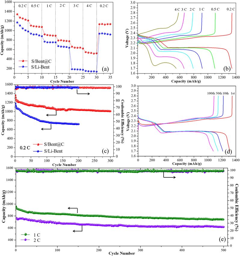
Making of stable and high-rate Li-S batteries 21
(MOFs) [9], layered metal oxides [10], MXenes [11], fluori- Through this approach, a N-doped carbon-coated interca-
nated carbon [12], and so forth have been widely studied as lated-bentonite composite sulfur host (denoted as Bent@C)
sulfur hosts for improving the capacity and cyclic/rate per- with efficient ion transport pathways and interconnected
formance of Li–S batteries. Although many of these mate- three-dimensional (3D) conductive networks can be con-
rials exhibit good performances as sulfur hosts, the lithium- trollably constructed. This strategy delivers the following
ion diffusion rate and LiPSs conversion kinetics in high advantages:
sulfur loading cathodes are still unsatisfactory. In addition, (i) Through regulating the interlayer distance of bento-
the high cost and complex preparation processes involved nite by simple inorganic/organic intercalation, a fast
also limit their applications. Recently, researchers have lithium-ion transport pathway can be constructed
been exploring natural clay minerals (e.g., bentonite [13], (ii) The organic intercalation agent-derived carbon in
halloysite [14], and vermiculite [15]) as sulfur hosts, and the interlayer combines with PDA-derived carbon
impressive achievements were obtained. Especially, as a (PDA-C) on the surface, endowing Bent@C with an
class of naturally existing two-dimensional (2D) materials, interconnected 3D conductive network which effec-
bentonite has numerous advantages, such as low cost, tively improves the conductivity of this composite
widespread abundance, and environmental friendliness. bentonite host
In addition, bentonite possesses a large interlayer space (iii) The alumina-silicate components of bentonite clay
and a high adsorption capacity [16], which makes it a and abundant N-doping of the carbon conductive
potential ideal sulfur host. As for its structure, bentonite networks provide a strong chemical adsorption of
consists of solid 2D layers, and each layer includes two LiPSs
silica tetrahedral sublayers sandwiching a central alumina (iv) This synthetic route is both facile and economical,
octahedral sublayer; between these layers, van der Waals and thus highly suitable for large-scale production.
forces are formed with hydrated cations balancing the As a result, the obtained S/Bent@C cathode can
charge [17]. This unique structure can facilitate fast Li ion exhibit significantly improved electrochemical per-
transport. Recent research reports from He’s group have formance. Furthermore, this work provides an eco-
demonstrated that the orderly layered structure of lithium- nomical and effective strategy for the construction of
bentonite provides an atomic interlamellar ion path which efficient ion transport pathways and conductive net-
is highly desirable in electrodes and separators, resulting works in high sulfur loading cathodes by using 2D
in rapid lithium-ion transport [18,19]. layered clay materials.
However, the poor conductivity of bentonite has lim-
ited its application in Li–S battery cathodes, which, to the
best of our knowledge, is probably the main reason for
the rarely successful attempts in improving the perfor- 2 Experimental
mance of Li–S batteries with bentonite as a sulfur host.
Moreover, current research has only focused on lithium-
bentonite which has a smaller interlayer space than raw 2.1 Synthesis of inorganic/organic
bentonite [13], implying that the ion transport pathways intercalated-bentonite
are very narrow and the lithium-ion diffusion barrier still
needs to be further reduced to obtain a faster lithium-ion In order to prepare inorganic/organic intercalated-bento-
transport. nite, a pillaring solution of Al Keggion ions (hydroxy-
Carbon materials have been widely explored for bat- aluminum oligomeric cations, [Al13O4(OH)24·(H2O)12]7+,
teries due to their chemical inertness, high electron con- denoted as Al13) was first prepared by slowly adding a
ductivity, facile control over transformation from amor- 0.2 M NaOH solution to a 0.2 M AlCl3 solution under con-
phous to crystalline structure, and low synthesis cost [20]. stant stirring at 60°C until the OH−/Al3+ ratio reached a
Inspired by the above consideration, herein, the inter- value of 2.4 [21]. The resultant solution was subsequently
lamellar pore structure of bentonite is regulated through stored at 60°C for two days. The organic intercalation
traditional inorganic/organic intercalation modification solution of chitosan (CS) was prepared by dissolving chit-
methods, and polydopamine (PDA) is coated onto the osan (deacetylation degree of 95%, average molecular
modified bentonite. Subsequently, the organic intercala- weight of 60,000 Da) in a 1% (v/v) aqueous acetic acid
tion agent and PDA are simultaneously carbonized for solution at a concentration of 1 wt% with stirring for
in situ synthesis of nano conductive carbon materials not 6 h [22]. Meanwhile, cation exchange was carried out
only on the surface, but also in the interlayers of bentonite. for raw bentonite to prepare lithium-bentonite (Li-Bent).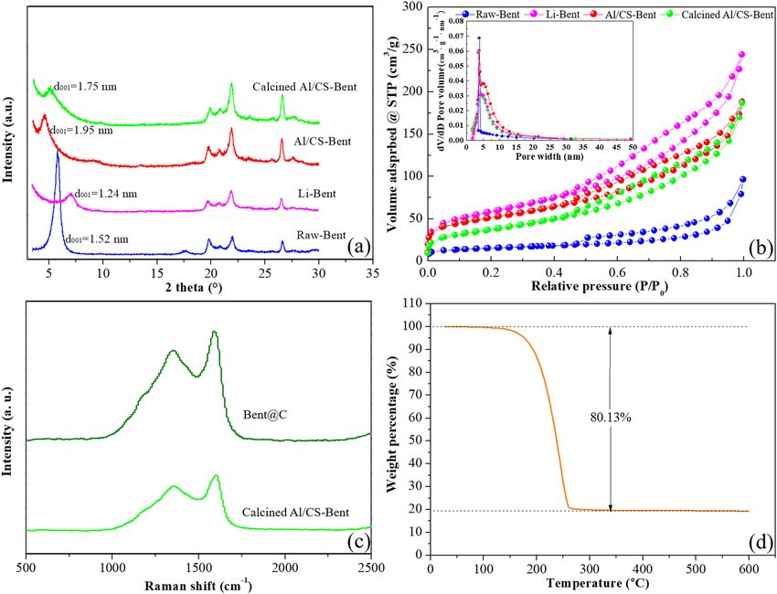
22 Lian Wu et al.
Typically, the raw bentonite (with a cation exchange capa- Teflon container that was filled with argon, and then heated
city (CEC) of 91 mmol (100 g−1)) was treated with 0.5 M in an oven at 155°C for 12 h. After cooling down, the
H2SO4 solution at 60°C for 2 h for full protonation to obtain obtained S/Bent@C was taken and homogenously ground
active bentonite. The active bentonite was then converted for 20 min to form a uniform powder. For comparison, S/Li-
to Li-Bent via treatment with 1 M LiOH at 60°C for 1 h [13]. Bent composite was also prepared via the same method.
After each cation exchange process, the obtained material
was washed with deionized water (DI water) for three
times. Finally, the prepared Li-Bent was added to DI water,
forming a 2 wt% clay suspension with stirring for 2 h at 2.4 Polysulfide adsorption tests
60°C, then the pillaring solution of Al13 (with the ratio of
10 mmol Al3+ g−1 bentonite) and the organic intercalation Li2S and sublimed sulfur, with a molar ratio of 1:5, were
solution of chitosan (with the ratio of glucosamine (MW = dissolved in a mixed solvent of 1,2-dimethoxyethane/1,3-
161 g mol−1) among chitosan to the CEC of Li-Bent was 1:1) dioxolane (DME/DOL, 1:1 v/v) under vigorous stirring at
were simultaneously added dropwise into 100 mL of the 50°C to obtain the 0.05 M Li2S6 solution. Adsorption tests
clay suspension with stirring for 6 h at 60°C. After one day were performed to compare the adsorption capacities of
of aging, the prepared product was washed several times Bent@C, Li-Bent, and PDA-C. Typically, 20 mg of adsor-
with DI water and vacuum dried at 80°C for 12 h to obtain bent was added into 10 mL of the obtained Li2S6 solution,
dry inorganic/organic intercalated-bentonite (denoted as followed by stirring for 1 min and standing for 12 h. The
Al/CS-Bent) powder. resultant solutions were compared with pure Li2S6 solu-
tion in the glass vial.
2.2 Synthesis of the carbon-coated 2.5 Materials characterization
intercalated-bentonite composites
The morphological characterization and elemental map-
PDA-coated intercalated-bentonite (denoted as Bent@PDA) ping were performed via Scanning Electron Microscopy
was prepared according to a procedure reported in literature (SEM) using a Zeiss Sigma 300 system coupled with a
[23]. Typically, 1 g of Al/CS-Bent was ultrasonically dis- Bruker XFlash6 X-ray energy dispersive spectroscopy
persed in 200 mL of Tris-HCl buffer solution for 5 min. (EDS). Transmission Electron Microscopy (TEM, FEI Talos
Dopamine hydrochloride (1 g) was dissolved in 100 mL of F200s) was used to observe the carbon layer and the
Tris-HCl buffer solution and then added dropwise into the layered structure. The X-ray diffraction (XRD) patterns
above suspension under constant stirring at room tem- were recorded employing a high-power X-ray diffraction
perature for 24 h with a stirring rate of 300 rpm. The mix- (XRD, D8 Rigaku 9000) system with Cu Kα radiation.
ture was subjected to filtration and the filtered product was Nitrogen adsorption and desorption isotherms were
washed several times with DI water and vacuum dried detected with a Micromeritics ASAP 2460 system at 77 K.
overnight at 60°C to obtain the Bent@PDA precursor. Sub- Thermogravimetric (TG) analysis was performed using a
sequently, the Bent@PDA precursor was heated at 700°C TGA Q5000 analyzer over a temperature range from 20 to
for 2 h under an argon atmosphere at a heating rate of 600°C with a heating rate of 10°C min−1 in an N2 atmo-
5°C min−1 to produce the carbon-coated intercalated-ben- sphere to determine the sulfur content of the composite
tonite composites (denoted as Bent@C). cathodes. The Raman experiments were performed using a
RM 2000 Microscopic Confocal Raman Spectrometer with
a 532 nm laser. The chemical states of C, N, and S in the
samples were determined by X-ray photoelectron spectro-
2.3 Synthesis of the sulfur/Bent@C scopy (XPS, 250XI, EscaLab).
composites
The sulfur/Bent@C (S/Bent@C) composites were synthe-
sized by a commonly used melt-diffusion method. The 2.6 Electrochemical characterization
as-prepared Bent@C and sublimed sulfur were mixed
with a weight ratio of 2:8 and homogenously ground for The composite cathodes were prepared by a traditional
∼10 min. The mixture was then transferred into a sealed slurry coating method. Electrode materials, carbon black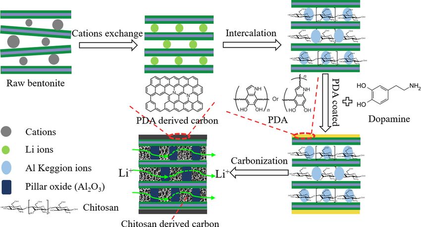
Making of stable and high-rate Li-S batteries 23
(Super P) and polyvinylidene fluoride (PVDF), were uni- carbon on the surface and in the interlayer of bentonite
formly mixed at a weight ratio of 7:2:1 in N-methyl pyrro- simultaneously, and the generated N-doped carbon can
lidone (NMP). The resulting slurry was then coated onto achieve a high electronic conductivity of 0.203 S cm−1
an aluminum foil and dried overnight in a vacuum oven [24]. Therefore, an interconnected 3D carbon conductive
at 60°C. Finally, the coated aluminum foil was cut into network and an efficient ion transport pathway are con-
discs with a diameter of 12 mm to obtain electrodes. The trollably constructed. It is worth noting that the thermal
areal sulfur loading was controlled from 1.2 to 3.0 stability of bentonite is greatly improved due to the alu-
mg cm−2. For electrochemical measurements, CR2025 coin minum pillared effect, so that it can bear high tempera-
cells were assembled in a glove box that was filled with ture treatment even above 700°C without any collapse of
argon. Lithium foils and Celgard 2400 membrane were the aluminosilicate layered structure [21]. Hence, fol-
used as the anode and separator, respectively. The elec- lowing the procedure demonstrated above, the Bent@C
trolyte was 1.0 M lithium bis(trifluoromethanesulphonyl) host material with a high electrical conductivity and fast
imide (LiTFSI) in the binary solvent consisting of 1,3- lithium-ion transport pathways can be prepared. During
dioxolaneand (DOL) and 1,2-dimethoxyethane (DME) (1:1 the charge/discharge cycling processes, the carbon con-
by volume) with 2.0 wt% LiNO3 as an additive. The elec- ductive network can facilitate electron transport, permit-
trolyte was added at a quantity of 15 μL per mg of sulfur. A ting the electrons to fully contact with the sulfur atoms,
multi-channel battery test system (NEWARE BTS-4000) thus enhancing the specific capacity of the Li–S batteries.
was employed for the galvanostatic charge/discharge Meanwhile, the combination of the large basal spacing
tests at different current densities within a cutoff voltage and the interlamellar porous carbon structure can pro-
window of 1.7–2.8 V. Employing a zennium pro-electro- vide efficient lithium-ion transport pathways which
chemical workstation, cyclic voltammetry (CV) measure- readily facilitate lithium-ion transport within the entire
ments were conducted between 1.5 and 3.0 V at different sulfur cathode. Moreover, polar bentonite aluminosili-
scan rates, and electrochemical impedance spectroscopy cate sheets and N-doped carbon can effectively prevent
(EIS) was performed by applying an AC amplitude of the migration of dissolved LiPSs in the cathode region,
5 mV in the frequency range of 0.01–105 Hz. thus effectively inhibiting the shuttle effect during the
long-term cycling.
3 Results and discussion 3.2 Morphology and structure
characterization
3.1 Design and synthesis of the S/Bent@C
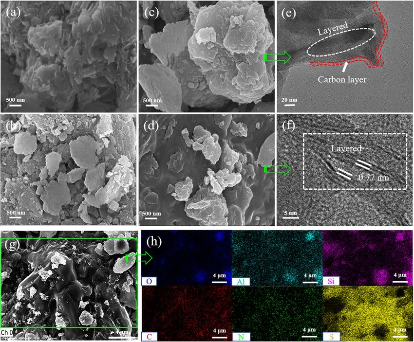
material The morphologies of Raw-Bent, Al/CS-Bent, Bent@C, and
S/Bent@C samples are shown in Figure 2. The Raw-Bent
A schematic illustration of the synthesis procedure for is revealed to be aggregates of lamellar particles with
Bent@C host is displayed in Figure 1. The aluminosilicate a porous structure (Figure 2a). After the intercalation
sheets in raw bentonite are disordered as the cations con- process with Al Keggion ions and CS, the morphology
tained in the interlayer (i.e., Na+, Mg2+, Ca2+) are highly become more porous and rougher, with many relatively
variable in size and distribution. For the synthesis, the small particles becoming visible (Figure 2b). Upon coat-
cations in the interlayer of raw bentonite are first con- ing with carbon, the morphology of the material becomes
verted to Li+ through a general ion exchange approach. very smooth (Figure 2c) due to the uniform structure of
As a result, the aluminosilicate sheets are converted from the PDA-C [25]. The TEM images (Figure 2e and Figure S1)
a disordered to an ordered structure [13]. An inorganic- further confirm the presence of a uniform carbon coating
organic intercalation modification is subsequently per- layer with a thickness of ∼10 nm on the surface of Al/CS-
formed, during which Al Keggion ions and CS molecules Bent. With a high sulfur content of 80%, some agglomera-
are intercalated into the interlayer spaces to enlarge the tion is observed in the SEM image of S/Bent@C (Figure 2d),
basal spacing of the bentonite. The intercalated-bento- indicating that the sulfur exists both inside the pores and
nite is then coated with PDA through the self-polymeri- outside on the surface of bentonite as the pore volume of
zation of dopamine, followed by heat treatment at 700°C the modified bentonite is still not enough for such high
for 2 h. During heat treatment, the PDA coating film and sulfur content. The TEM images (Figure 2f and Figure S2)
the interlamellar CS are carbonized, forming N-doped further reveal the nanostructure of S/Bent@C, showing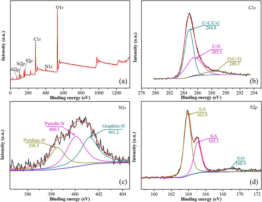
24 Lian Wu et al. Figure 1: Schematic illustration of the synthesis of Bent@C host materials for sulfur cathodes. that the bentonite still has a superwide interlayer distance aluminosilicate layer (∼0.96 nm) [26], the corresponding of 0.77 nm after the diffusion of melted sulfur into Bent@C. basal spacing is 1.73 nm. The TEM images also show that Taking into account the thickness of the bentonite the impregnated sulfur is well-distributed with little Figure 2: SEM images of Raw-Bent (a), Al/CS-Bent (b), Bent@C (c), S/Bent@C (d), and corresponding elemental mapping images of O, Al, Si, C, N, and S (g and h). TEM images of Bent@C (e) and S/Bent@C (f).
Making of stable and high-rate Li-S batteries 25
agglomeration. The element mapping of the S/Bent@C 1.95 nm. However, after calcination, the (001) reflection
composite (Figure 2g and h) further demonstrates a peak is observed at 2θ = 5.06°, implying a decreased basal
homogeneous distribution of oxygen, aluminium, silicon, spacing (1.75 nm) which is caused by sintering of the par-
carbon, nitrogen, and sulfur within the material, which ticles at high temperature. In spite of the decrease, the
also confirms the successful formation of a N-doped layered structure is well-retained and the basal spacing
carbon-coated structure on the intercalated-bentonite. of 1.75 nm is still desirable for the construction of efficient
The XRD patterns of Raw-Bent, Li-Bent, Al/CS-Bent, ion transport pathways in the interlayer of bentonite. The
and calcined Al/CS-Bent are shown in Figure 3a. The efficient ion transport pathways will provide S/Bent@C
Raw-Bent exhibits the strongest (001) reflection at 2θ = with fast ion diffusion and exchange properties that greatly
5.81°, corresponding to a basal spacing of 1.52 nm. As improve the rate performance even with high sulfur loading
lithium ions are smaller than the interlamellar cations [13]. These XRD data are highly consistent with the TEM
of Raw-Bent, the Li-Bent shows a (001) reflection peak results shown in Figure 2f.
at 2θ = 7.12° which is associated with a smaller basal In order to further understand the effect of inter-
spacing of 1.24 nm, and this value is very close to the calation on the porous structure of bentonite, nitrogen
characteristic basal spacing of sodium bentonite studied adsorption/desorption tests were performed. The nitrogen
in our previous work [27]. After intercalated by Al Keggion adsorption–desorption isotherms of the raw and modified
ions and CS, the basal spacing increases significantly, bentonite samples are shown in Figure 3b. All curves are of
which is reflected by the shift of the (001) reflection peak type II adsorption isotherm exhibiting typical H3 type hys-
of Al/CS-Bent to a lower position (2θ = 4.52°). Specifically, teresis loops according to the IUPAC classification. The
the basal spacing of the Al/CS-Bent is determined to be results represent a typical behavior of slit-shaped pores,
Figure 3: (a) XRD patterns; (b) nitrogen adsorption-desorption isotherms and pore size distributions (inset) of raw and modified bentonite;
(c) Raman spectra of Bent@C and calcined Al/CS-Bent. (d) TG curve of S/Bent@C.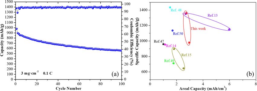
26 Lian Wu et al.
and it is evident that the configuration of parallel plates Table 1: Pore structure characteristics obtained from conventional
of clay minerals is fairly preserved [28]. Meanwhile, this analysis of nitrogen isotherms
type of adsorption–desorption isotherm indicates multi-
layer nitrogen adsorption and capillary condensation Sample SBET Pore Pore volume
(m2/g) diameter (nm) (cm3/g)
within the mesopores of the clay samples [28]. As illu-
strated in Figure 3b, raw bentonite has a monomodal Raw-Bent 50.8 5.75 0.10
distribution of pore diameters centered at ∼3.0 nm. After Li-Bent 204.7 7.27 0.22
Al/CS-Bent 178.1 9.21 0.24
modification via acid leaching and lithium-ion exchange,
Calcined Al/ 133.8 6.60 0.25
numerous pores with diameters of 4–15 nm are formed CS-Bent
and the distribution of the pore diameters is broadened.
The pore diameter further increases with inorganic/
organic intercalation due to interlamellar expansion of are observed at 1,356 and 1,606 cm−1, respectively. The
the bentonite as the larger inorganic/organic cations (or ratio of the integrated intensity of the D band and the G
molecules) often act as “pillars” to support the alumino- band (ID/IG) are 2.46 and 2.85 for Bent@C and calcined Al/
silicate sheets apart [29]. After calcination at elevated CS-Bent composites, respectively, demonstrating that the
temperatures, the pore size distribution curve shifts to PDA- and CS-derived carbon has a significant number of
the left slightly and the amount of micropores increases, defects and edges attributed to the highly porous structure
which could be attributed to the conversion of CS to micro- and abundant nitrogen doping [23,33].
porous carbon in the bentonite host. This nanoporous TGA was used to measure the sulfur content in the S/
conductive architecture can provide both nanoporous Bent@C composite materials. The TG curve of S/Bent@C
channels for low-resistant ion diffusion and nano-sized (Figure 3d) displays a noticeable weight loss of 80.13 wt%
skeletons for fast electron transfer [30]. resulting from the evaporation of sulfur. The sulfur con-
Table 1 shows the textural properties including the tent determined by TGA is basically in accordance with
BET surface area (SBET), pore diameter, and pore volume the initial addition amount of sulfur for the preparation of
assigned to the raw and modified bentonite samples. The S/Bent@C.
SBET and pore volume of Li-Bent are much higher than The element composition, bond state, and valence
that of the raw bentonite, which is caused by the open state of the S/Bent@C composite were analyzed by XPS,
edges of the clay crystals and the removal of impurities and the results are shown in Figure 4. In the XPS survey
from the interlayer of bentonite by the acid leaching pro- spectra, the Al2p, Si2p, S2p, C1s, N1s, and O1s peaks are
cess [31]. Although the basal spacing of Li-Bent increases detected at the respective binding energies of 74.86,
significantly after intercalation by Al Keggion ions and 103.04, 163.91, 284.8, 400.46, and 532.15 eV (Figure 4a).
CS, the SBET and pore volume decrease. This may be As demonstrated in Figure 4b, the C1s band in the high-
attributed to the pore blocking effect, as a larger exchange resolution spectrum can be deconvoluted into three
cation/molecule (Al Keggion ions and CS) may clog some peaks at 284.8, 285.5, and 288.5 eV, corresponding
of the smaller pores [29]. The calcination process causes to C]C/C–C, C–N, and O–C]O moieties, respectively
partial destruction of the pore structure at high tempera- [34,35]. The existence of C–N bonding peak further con-
ture, resulting in a reduced SBET of the intercalated-bento- firms the successful doping of N into the conductive
nite from 178.1 to 133.8 m2/g. This is consistent with the carbon layer. As for the N1s spectrum (Figure 4c), it
reduction of basal spacing as calculated based on XRD can be deconvoluted into three peaks at 398.5, 400.1,
results. Meanwhile, the total pore volume increases and 401.7 eV, which are respectively assigned to pyri-
slightly while the pore diameter decreases, further sug- dinic-N, pyrrolic-N, and graphitic-N [34]. As shown in
gesting the formation of porous carbon with abundant Figure 4d, the two peaks at 163.9 and 165.1 eV divided
micropores. from the S2p spectrum are assigned to sulfur from S–S
Raman spectra of Bent@C and calcined Al/CS-Bent bonds [36]. Moreover, the S2p spectrum exhibits a clear
were recorded to gain further insight regarding the struc- peak at 168.9 eV corresponding to sulfur–oxygen (S–O)
ture of the composites. As shown in Figure 3c, the Bent@C bond, which plays a critical role in the immobilization
composites exhibit a typical D peak at 1,353 cm−1 (defects of sulfur in S/Bent@C composites [34]. The presence
and disorder in carbon) and a G peak at 1,590 cm−1 (corre- of S–O bond demonstrates that the oxygen-containing
sponding to the stretching mode of C–C bonds of typical groups in PDA-C and bentonite aluminosilicate sheets
graphite) [32]. Meanwhile, the calcined Al/CS-Bent sample can bond with sulfur species to promote the sulfur affi-
has a very similar peak appearance and the D and G peaks nity of the electrode [37].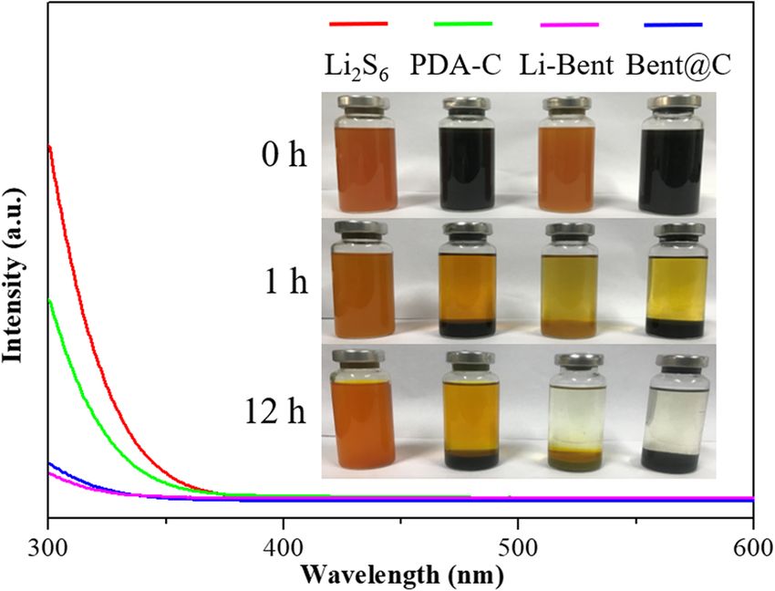
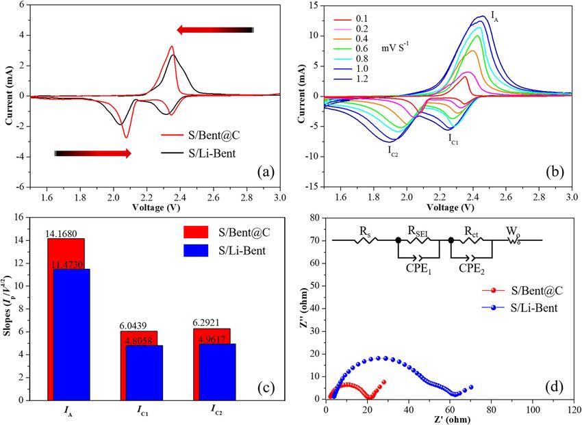
Making of stable and high-rate Li-S batteries 27 Figure 4: (a) XPS spectrum of S/Bent@C. (b–d) High-resolution XPS spectra of C1s, N1s, and S2p. 3.3 Polysulfide adsorption 3.4 Electrochemical performance In order to further prove the effective trapping of LiPSs by The electrochemical performance of S/Bent@C was inves- Bent@C, adsorption experiments were performed and tigated in Li–S batteries with lithium metal serving as photographs demonstrating the adsorption performance the anodes. CV tests were conducted at a scan rate of are shown in the insets of Figure 5. Specifically, the same 0.1 mV s−1 within the voltage range of 1.5–3.0 V (vs Li/ amount of PDA-C, Li-Bent, and Bent@C were immersed Li+). As shown in Figure 6a, S/Li-Bent exhibits two typical in a Li2S6 solution for 12 h. The color of the Li2S6 solution reduction peaks at 2.31 and 2.04 V, which are assigned to becomes almost transparent after exposure to Bent@C the multistep reduction process (i.e., from solid sulfur and Li-Bent, while it only fades slightly from dark brown to soluble long-chain LiPSs (Li2Sx; x = 8, 6, 4) and to light brown after exposure to PDA-C. The strong adsorp- finally to the end-product Li2S2/Li2S). In the subse- tion capacities of Li-Bent and Bent@C are further verified quent charging process, the peak at 2.38 V is assigned by ultraviolet-visible (UV-vis) spectroscopy where the absor- to the reversible oxidation process (i.e., from Li2S/Li2S2 bance corresponding to Li2S6 observed in the 300–400 nm to LiPSs and eventually back to solid sulfur) [38]. Com- region is negligible. In contrast, a strong absorbance corre- pared to S/Li-Bent, the redox peaks of S/Bent@C shift sponding to Li2S6 is seen for the solution exposed to PDA-C. to 2.34/2.08 and 2.35 V, respectively. Moreover, the The results of the adsorption experiments demonstrate redox peaks of S/Bent@C are stronger and sharper that the N-doped carbon derived from PDA has a certain than that of S/Li-Bent. Such a peak appearance of S/ absorbing capacity for LiPSs, but not as strong as those of Bent@C indicates that the electrochemical polarization the Lewis acid sites on the broken edges of the bentonite of the electrode is effectively mitigated, and the redox aluminosilicate sheets. kinetics are enhanced [39].
28 Lian Wu et al.
The cycle voltammograms of S/Bent@C and S/Li-
Bent were further recorded at different scanning rates
ranging from 0.1 to 1.2 mV s−1 (Figure 6b and Figure S3).
At all scan rates, both S/Bent@C and Li-Bent/S show two
reduction peaks and one oxidation peak. In addition,
with the increasing scan rate, the reduction peaks shift
to a lower voltage, while the oxidation peaks shift in the
opposite direction. As the polysulfide conversion in a
Li–S battery is a diffusion-limited process, all the peak
currents (IC1, IC2, and IA) are linear with the square root of
scan rates, from which the lithium-ion diffusion rate can
be estimated by using the classical Randles–Sevcik equa-
tion [40].
Figure 5: UV-vis spectra (300–600 nm) of the Li2S6 solution after
IP = 2.69 × 10 5n3 / 2ADLi1 / 2 V 1 / 2 ΔCLi
exposure to PDA-C, Li-Bent, and Bent@C, respectively, for 12 h. The
where IP is the cathodic/anodic peak current, n is the
inset images show the color changes of the Li2S6 solution during
charge transfer number, A is the active electrode area,
exposure to different sorbent materials.
DLi is the lithium-ion diffusion coefficient, V is the scan
rate, and ΔCLi is the change of the lithium-ion concentra-
tion corresponding to the electrochemical reactions.
Figure 6: (a) CV curves of S/Bent@C and S/Li-Bent batteries at the scan rate of 0.1 mV s−1. (b) CV curves of S/Bent@C battery under different
scan rates ranging from 0.1 to 1.2 mV s−1. (c) The value of IP/V1/2 from Figure S4 that represents the lithium-ion diffusion capability. (d) EIS
curves and the equivalent circuit (inset) of S/Bent@C and S/Li-Bent batteries.Making of stable and high-rate Li-S batteries 29 Since the values of n, A, and ΔCLi are constant, the slopes KC2 = 6.2921; KC1 = 6.0439) than the S/Li-Bent cathode of the IP − V1/2 lines are positively correlated to the cor- (KA = 11.4730; KC2 = 4.8058; KC1 = 4.9617) (Figure 6c responding lithium-ion diffusion rate [40]. Clearly, the S/ and Figure S4), indicating a much faster diffusion and Bent@C cathode exhibits larger slopes (KA = 14.1680; reaction kinetics of S/Bent@C compared with that of Figure 7: (a) Rate performances of S/Bent@C and Li-Bent/S electrodes with a sulfur loading of 1.2 mg cm−2. (b) Galvanostatic charge/ discharge profiles of S/Bent@C electrode with a sulfur loading of 1.2 mg cm−2 at various C-rates. (c) Cycling performances of S/Bent@C and Li-Bent/S electrodes with a sulfur loading of 2 mg cm−2 at 0.2C. (d) Galvanostatic charge/discharge profiles of S/Bent@C electrode with a sulfur loading of 2 mg cm−2 at different cycles. (e) Long-term cycling performance of S/Bent@C electrode with a sulfur loading of 2 mg cm−2 at 1 and 2C.
30 Lian Wu et al.
S/Li-Bent cathode [13]. The results of CV tests clearly 1135.2 mA h g−1 can be restored, revealing a superior rate
verify that the lithium-ion diffusion rate is promoted capability and reversible performance at high-rate condi-
and the electron transfer barrier is reduced, owing to tions. In addition, the corresponding charge and dis-
the construction of ion transport pathways and conduc- charge profiles are shown in Figure 7b and Figure S5. A
tive networks in the composite S/Bent@C cathode. certain charge and discharge platform effect is main-
The resistance performance of batteries based on S/ tained for the S/Bent@C cathode even at a high current
Bent@C and S/Li-Bent cathodes was further investigated rate of 4C, indicating that the electrochemical reactions
via EIS (Figure 6d). The inset shows the equivalent cir- from sulfur to long-chain LiPSs and then to Li2S2/Li2S are
cuits corresponding to these two batteries. According to continued to be effective and suggesting a kinetically
the fitting results, the ohmic resistances (Rs) correspond efficient reaction process with a small barrier [39]. How-
to the total resistances of the electrodes, current collec- ever, once the current rate increases to 3C (Figure S5a),
tors, electrolyte and separator, the charge transfer resis- the galvanostatic charge/discharge profiles of S/Li-Bent
tance (Rct) related to the interfacial phenomena and reac- cathode exhibit distinct distortion and overpotential and
tions between electrode and electrolyte, and the solid the charge and discharge platform effect even disappears.
electrolyte interface resistance (RSEI) [41,42] were obtained, These phenomena confirm that the free ion/electron trans-
and the values are listed in Table S1. The S/Li-Bent bat- port, induced by the efficient ion transport pathways in the
tery exhibits much higher Rs, RSEI, and Rct values due to interlayer of bentonite combined with the high electronic
the poorer electrical conductivity of Li-Bent compared conductivity of the interconnected 3D conductive carbon
with Bent@C [43]. In addition, the oblique line at the networks, confers fast redox kinetics and high sulfur utili-
area of low frequency represents the Warburg resistance zation to the S/Bent@C cathode [41].
which reflects the ion diffusion properties [44,45]. The The cycling performances of S/Bent@C and S/Li-
S/Bent@C cathode shows a higher Warburg slope than Bent cathodes at the current rate of 0.2C are shown in
that of Li-Bent cathode, indicating that the S/Bent@C Figure 7c. The S/Bent@C cathode displays a much higher
cathode has facilitated ion diffusion behavior. initial discharge capacity of 1,361 mA h g−1 compared with
The rate performance was investigated by galvano- that of the Li-Bent/S cathode (1181.60 mA h g−1). After 200
static charge/discharge tests at various current rates. As cycles, the discharge capacities of the S/Bent@C and Li-
shown in Figure 7a, the S/Bent@C cathode exhibits a Bent/S cathodes decrease to 1039.4 and 722.20 mA h g−1,
constantly higher specific discharge capacity than the respectively, and the S/Bent@C cathode retains ∼74% of
Li-Bent/S cathode along with the increase of the current the starting capacity over 300 cycles. Meanwhile, the S/
rate from 0.2 to 0.5, 1, 2, 3, and 4C, with the average Bent@C cathode also maintains a constantly high cou-
reversible capacities of 1263.8, 1089.1, 903.8, 787.6, 642.6, lombic efficiency of over 98% upon 300 cycles. Further-
and 531.3 mA h g−1, respectively. When the current den- more, Figure 7d and Figure S5b show the galvanostatic
sity recovers to 0.1C, a high discharge capacity of charge/discharge profiles of S/Bent@C and S/Li-Bent
Figure 8: (a) Cycling performance of S/Bent@C electrode with a sulfur loading of 3 mg cm−2 at 0.1C. (b) Areal capacity and specific capacity
comparisons between the Li–S battery in this work and recently reported Li–S batteries based on clay host materials [13–15,47–50].Making of stable and high-rate Li-S batteries 31
cathodes at different cycles. With the increase of cycle spaces of bentonite through the intercalation-carboniza-
number, obvious overpotential can be observed for S/ tion of chitosan. In the meantime, the efficient ion trans-
Li-Bent, while S/Bent@C displays a much lower overpo- port pathways in the interlayer of bentonite are control-
tential. These results strongly indicate that the Bent@C lably constructed via the inorganic/organic intercalation
host material has a superior structure which suppresses process, which improves the lithium-ion diffusion effi-
the shuttle effect, reduces the surface passivation, and ciency and facilitates energy conversion via sulfur redox
enhances sulfur reaction reversibility, owing to the com- reactions. Therefore, the S/Bent@C cathode, with the N-
bination of strong chemical sulfur confinement and free doped carbon-coated intercalated-bentonite as the sulfur
ion/electron transport. host materials, provides improved rate capabilities and
Figure 7e displays the long-term cycling perfor- cycling stability compared with the Li-Bent/S cathode
mances of the S/Bent@C cathodes at higher current den- which employs lithium-bentonite as the sulfur host. This
sities. After 500 cycles at 1 and 2C, the S/Bent@C cathode work would broaden the applicability of bentonite clay in
still delivers high capacities of 743.3 and 618.1 mA h g−1, energy storage and provide an economical and efficient
with only 0.045 and 0.039% capacity decay per cycle, host material for the design of advanced Li–S batteries.
respectively. Besides, under higher sulfur loading, the
S/Bent@C cathode also exhibits excellent cycle perfor- Acknowledgments: The authors thank Tengyou Wei,
mances. As shown in Figure 8a, with a sulfur loading of Professor of Chemical Engineering at Guangxi University,
3 mg cm−2, the S/Bent@C cathode can reveal discharge for his helpful discussions of the modification study of the
capacities of 560.2 mA h g−1 after 100 cycles, suggesting bentonite host.
that a kinetically efficient reaction process occurs with a
small energy barrier for free diffusion of lithium ions Funding information: This work was financially sup-
toward the interior of the electrode [46]. The electroche- ported by the China Postdoctoral Science Foundation
mical performance parameters of recently reported Li–S (Grant No. 2020M672549), the National Natural Science
batteries based on different clay host materials were sum- Foundation of China (Grant No. 52003111), and the GDAS’
marized in Figure 8b. Among them, Ref. [13] reported a Project of Science and Technology Development (Grant
high areal capacity up to ∼6 mA h/cm2 based on bento- Nos. 2021GDASYL-20210103097, 2020GDASYL-20200102029,
nite. The areal capacities were all lower than 3 mA h/cm2 and 2020GDASYL-20200102028).
based on the other types of clays [14,15,47–50]. Our cur-
rent work provided a highly competitive performance, Author contributions: All authors have accepted respon-
but high sulfur loading (>3 mg/cm2) cathodes are needed sibility for the entire content of this manuscript and
to be further studied. approved its submission.
The above experimental results show that Bent@C
is an ideal host material, providing plentiful efficient Conflict of interest: The authors state no conflict of
lithium-ion transport pathways for promoting ion trans- interest.
port, improving electron transport through the intercon-
nected 3D conductive carbon network, and trapping soluble
LiPSs via Lewis acid-base interactions as well as N-doped
carbon, thus resulting in enhanced redox kinetics and References
improved rate/cycle performances.
[1] Yang X, Peng Y, Hou J, Liu Y, Jian X. A review for modified Li
composite anode: principle, preparation and challenge.
Nanotechnol Rev. 2020;9(1):1610–24.
[2] Zhou L, Danilov DL, Eichel RA, Notten PHL. Host materials
4 Conclusions anchoring polysulfides in Li–S batteries reviewed. Adv Energy
Mater. 2020;20:2001304.
In summary, the use of the modified bentonite clay as a [3] Huang J, Lin Y, Yu J, Li D, Du J, Yang B, et al. N-doped foam
sulfur host is proposed herein to resolve the shuttle effect flame retardant polystyrene derived porous carbon as an effi-
of the LiPS and to promote lithium-ion transport in the cient scaffold for lithium-selenium battery with long-term
cycling performance. Chem Eng J. 2018;350:411–8.
cathodes of Li–S batteries. In order to enhance the con-
[4] Wang R, Yang J, Chen X, Zhao Y, Zhao W, Qian G, et al. Highly
ductivity of bentonite host, N-doped conductive carbon is dispersed cobalt clusters in nitrogen-doped porous carbon
not only deposited onto the surface of bentonite through enable multiple effects for high performance Li–S battery. Adv
PDA-C coatings, but also introduced into the interlayer Energy Mater. 2020;10(9):1903550.32 Lian Wu et al.
[5] Zhang J, Huang Z, He C, Zhang J, Mei P, Han X, et al. Binary [22] Darder M, Colilla M, Ruiz-Hitzky E. Biopolymer-clay nano-
carbon-based additives in LiFePO4 cathode with favorable composites based on chitosan intercalated in montmorillo-
lithium storage. Nanotechnol Rev. 2020;9(1):934–44. nite. Chem Mater. 2003;15(20):3774–80.
[6] Li MY, Carter R, Douglas A, Oakes L, Pint CL. Sulfur vapor- [23] Gu H, Xu X, Dong M, Xie P, Shao Q, Fan R, et al. Carbon
infiltrated 3D carbon nanotube foam for binder-free high areal nanospheres induced high negative permittivity in nanosilver
capacity lithium sulfur battery composite cathodes. ACS Nano. polydopamine metacomposites. Carbon. 2019;147:550–8.
2017;11(5):4877–84. [24] Zhang LL, Ma D, Li T, Liu J, Ding XK, Huang YH, et al.
[7] Wu Z, Yuan L, Han Q, Lan Y, Zhou Y, Jiang X, et al. Polydopamine-derived nitrogen-doped carbon-covered
Phosphorous/oxygen co-doped mesoporous carbon bowls as Na3V2(PO4)2F3 cathode material for high-performance Na-ion
sulfur host for high performance lithium–sulfur batteries. batteries. ACS Appl Mater Interfaces. 2018;10(43):36851–9.
J Power Sources. 2020;450:227658. [25] Li R, Parvez K, Hinkel F, Feng X, Müllen K. Bioinspired wafer-scale
[8] Ye Y, Wu F, Liu Y, Zhao T, Qian J, Xing Y, et al. Toward practical production of highly stretchable carbon films for transparent
high-energy batteries: a modular assembled oval-like carbon conductive electrodes. Angew Chem Int Ed. 2013;52(21):5535–8.
microstructure for thick sulfur electrodes. Adv Mater. [26] Chen B, Zhu L, Zhu J. Configurations of the bentonite-sorbed
2017;29(48):1700598. myristylpyridinium cation and their influences on the uptake
[9] Zheng Y, Zheng S, Xue H, Pang H. Metal-organic frameworks of organic compounds. Env Sci Technol.
for lithium–sulfur batteries. J Mater Chem A. 2005;39(16):6093–100.
2019;7(8):3469–91. [27] Zhao H, Liao B, Nian F, Wang K, Guo Y, Pang H. Investigation of
[10] Wang C, Yi Y, Li H, Wu P, Li M, Jiang W, et al. Rapid gas-assisted the clay sensitivity and cement hydration process of modified
exfoliation promises V2O5 nanosheets for high performance HPEG-type polycarboxylate superplasticizers. J Appl Polym Sci.
lithium–sulfur batteries. Nano Energy. 2020;67:104253. 2018;135(32):46572.
[11] Pang J, Mendes RG, Bachmatiuk A, Zhao L, Ta HQ, Gemming T, [28] Banković P, Milutinović-Nikolić A, Mojović Z, Jović-Jovičić N,
et al. Applications of 2D MXenes in energy conversion and Perović M, Spasojević V, et al. Synthesis and characterization
storage systems. Chem Soc Rev. 2019;48(1):72–133. of bentonites rich in beidellite with incorporated Al or Al-Fe
[12] Liu Y, Jiang L, Wang H, Wang H, Jiao W, Chen G, et al. A brief oxide pillars. Microporous Mesoporous Mater.
review for fluorinated carbon: synthesis, properties and 2013;165:247–56.
applications. Nanotechnol Rev. 2020;8(1):573–86. [29] Lee JF, Lee CK, Juang LC. Size effects of exchange cation on the
[13] Chen W, Lei T, Lv W, Hu Y, Yan Y, Jiao Y, et al. Atomic inter- pore structure and surface fractality of montmorillonite.
lamellar ion path in high sulfur content lithium-montmorillo- J Colloid Interface Sci. 1999;217(1):172–6.
nite host enables high-rate and stable lithium–sulfur battery. [30] Zeng W, Shu L, Li Q, Chen S, Wang F, Tao XM. Fiber-based
Adv Mater. 2018;30(40):1804084. wearable electronics: a review of materials, fabrication,
[14] Wang Y, Wang X, Ye H, Han K. Carbon coated halloysite devices, and applications. Adv Mater. 2014;26(31):5310–36.
nanotubes as efficient sulfur host materials for lithium sulfur [31] Komadel P. Acid activated clays: materials in continuous
batteries. Appl Clay Sci. 2019;179:105172. demand. Appl Clay Sci. 2016;131:84–99.
[15] Wu F, Lv H, Chen S, Lorger S, Srot V, Oschatz M, et al. Natural [32] Ghouri ZK, Motlak M, Afaq S, Barakat NAM, Abdala A. Template-
vermiculite enables high-performance in lithium–sulfur bat- free synthesis of Se-nanorods-rGO nanocomposite for applica-
teries via electrical double layer effects. Adv Funct Mater. tion in supercapacitors. Nanotechnol Rev. 2019;8(1):661–70.
2019;29(27):1902820. [33] Tian W, Zhang X, Guo Y, Mu C, Zhou P, Yin L, et al. Hybrid silica-
[16] Wu L, Wei T, Tong Z, Zou Y, Lin Z, Sun J. Bentonite-enhanced carbon bilayers anchoring on FeSiAl surface with bifunctions
biodiesel production by NaOH-catalyzed transesterification of of enhanced anti-corrosion and microwave absorption.
soybean oil with methanol. Fuel Process Technol. Carbon. 2021;173:185–93.
2016;144:334–40. [34] Zuo Y, Ren P, Zhao M, Su W, Chen Y, Tang Y, et al. Stable
[17] Sun Y, Mei J, Hu H, Ying J, Zhou W, Zhao X, et al. In situ poly- lithium–sulfur batteries with high sulfur content fabricated by
merization of exfoliated structure PA6/organo-clay nanocom- ultralight ochroma lagopus-derived carbon with dopamine
posites. Rev Adv Mater Sci. 2020;59(1):434–40. shell as sulfur host. J Alloy Comp. 2020;819:152995.
[18] Chen W, Hu Y, Lv W, Lei T, Wang X, Li Z, et al. Lithiophilic [35] Wang Y, Feng J, Jin L, Li C. Photocatalytic reduction of graphene
montmorillonite serves as lithium ion reservoir to facilitate oxide with cuprous oxide film under UV-vis irradiation. Rev Adv
uniform lithium deposition. Nat Commun. 2019;10:4973. Mater Sci. 2020;59(1):207–14.
[19] Zhao J, Chen D, Boateng B, Zeng G, Han Y, Zhen C, et al. Atomic [36] Wang DG, Li N, Hu Y, Wan S, Song M, Yu G, et al. Highly fluoro-
interlamellar ion path in polymeric separator enables long-life substituted covalent organic framework and its application in
and dendrite-free anode in lithium ion batteries. J Power lithium–sulfur batteries. ACS Appl Mater Interfaces.
Sources. 2020;451:227773. 2018;10(49):42233–40.
[20] Jian X, Wang H, Rao G, Jiang L, Wang H, Subramaniyam CM, [37] Chen H, Zhou G, Boyle D, Wan J, Wang H, Lin D, et al. Electrode
et al. Self-tunable ultrathin carbon nanocups as the electrode design with integration of high tortuosity and sulfur-philicity
material of sodium-ion batteries with unprecedented capacity for high-performance lithium–sulfur battery. Matter.
and stability. Chem Eng J. 2019;364:578–88. 2020;2(6):1605–20.
[21] Zhu J, Wen K, Wang Y, Ma L, Su X, Zhu R, et al. Superior thermal [38] Liu S, Zhang X, Wu S, Chen X, Yang X, Yue W, et al. Crepe cake
stability of Keggin-Al30 pillared montmorillonite: a compara- structured layered double hydroxide/sulfur/graphene as a
tive study with Keggin-Al13 pillared montmorillonite. positive electrode material for Li–S batteries. ACS Nano.
Microporous Mesoporous Mater. 2018;265:104–11. 2020;14(7):8220–31.Making of stable and high-rate Li-S batteries 33
[39] Zhou G, Liu K, Fan Y, Yuan M, Liu B, Liu W, et al. An aqueous [45] Lin Y, Huang J, Shi L, Cong G, Zhu C, Xu J. Combining
inorganic polymer binder for high performance lithium–sulfur Zn0.76Co0.24S with S-doped graphene as high-performance
batteries with flame-retardant properties. ACS Cent Sci. anode materials for lithium and sodium-ion batteries.
2018;4(2):260–7. Nanotechnol Rev. 2020;9(1):1227–36.
[40] Tao X, Wang J, Liu C, Wang H, Yao H, Zheng G, et al. Balancing [46] Zhou G, Wang DW, Li F, Hou PX, Yin L, Liu C, et al. A flexible
surface adsorption and diffusion of lithium-polysulfides on nanostructured sulphur-carbon nanotube cathode with high
nonconductive oxides for lithium–sulfur battery design. Nat rate performance for Li–S batteries. Energy Environ Sci.
Commun. 2016;7:11203. 2012;5(10):8901–6.
[41] Lei T, Hu Y, Chen W, Lv W, Jiao Y, Wang X, et al. Genetic [47] Cao Z, Ma C, Jia Y, Sun Z, Yue H, Yin Y, et al. Activated clay of
engineering of porous sulfur species with molecular target nest structure encapsulated sulfur cathodes for lithium–sulfur
prevents host passivation in lithium sulfur batteries. Energy batteries. RSC Adv. 2015;5(36):28349–53.
Storage Mater. 2020;26:65–72. [48] Pan J, Wu C, Cheng J, Pan Y, Ma Z, Xie S, et al. Sepiolite-sulfur
[42] Fu J, Ali R, Mu C, Liu Y, Mahmood N, Lau WM, et al. Large-scale as a high-capacity, high-rate performance, and low-cost
preparation of 2D VSe2 through a defect-engineering approach cathode material for lithium–sulfur batteries. J Power Sources.
for efficient hydrogen evolution reaction. Chem Eng J. 2015;293:527–32.
2021;411:128494. [49] Pei Y, Wang Y, Darraf Y, Chang AY, Zhao H, Liu X, et al.
[43] Shih HJ, Chang JY, Cho CS, Li CC. Nano-carbon-fiber-pene- Confining sulfur particles in clay nanotubes with improved
trated sulfur crystals as potential cathode active material for cathode performance of lithium–sulfur batteries. J Power
high-performance lithium–sulfur batteries. Carbon. Sources. 2020;450:227698.
2020;159:401–11. [50] Cen T, Zhang Y, Tian Y, Zhang X. Synthesis and electrochemical
[44] Lin J, Yin X, Pang H, Zhang L, Liao B, Xin M. Tuning the wrinkles performance of graphene@ halloysite nanotubes/sulfur com-
in 3D graphene architectures for mass and electron transport. posites cathode materials for lithium–sulfur batteries.
Adv Mater Interfaces. 2020;7(10):1902190. Materials. 2020;13(22):5158.You can also read