Electrode pooling can boost the yield of extracellular recordings with switchable silicon probes - Nature
←
→
Page content transcription
If your browser does not render page correctly, please read the page content below
ARTICLE
                   https://doi.org/10.1038/s41467-021-25443-4                OPEN

                  Electrode pooling can boost the yield of
                  extracellular recordings with switchable silicon
                  probes
                  Kyu Hyun Lee1,4, Yu-Li Ni 1,4, Jennifer Colonell2, Bill Karsh2, Jan Putzeys                                  3,   Marius Pachitariu   2,

                  Timothy D. Harris 2 & Markus Meister 1 ✉
1234567890():,;

                  State-of-the-art silicon probes for electrical recording from neurons have thousands of
                  recording sites. However, due to volume limitations there are typically many fewer wires
                  carrying signals off the probe, which restricts the number of channels that can be recorded
                  simultaneously. To overcome this fundamental constraint, we propose a method called
                  electrode pooling that uses a single wire to serve many recording sites through a set of
                  controllable switches. Here we present the framework behind this method and an experi-
                  mental strategy to support it. We then demonstrate its feasibility by implementing electrode
                  pooling on the Neuropixels 1.0 electrode array and characterizing its effect on signal and
                  noise. Finally we use simulations to explore the conditions under which electrode pooling
                  saves wires without compromising the content of the recordings. We make recommenda-
                  tions on the design of future devices to take advantage of this strategy.

                  1 Division
                          of Biology and Biological Engineering, Caltech, Pasadena, CA, USA. 2 HHMI Janelia Research Campus, Ashburn, VA, USA. 3 IMEC, Leuven, Belgium.
                  4
                   These authors contributed equally: Kyu Hyun Lee, Yu-Li Ni. ✉email: meister@caltech.edu

                  NATURE COMMUNICATIONS | (2021)12:5245 | https://doi.org/10.1038/s41467-021-25443-4 | www.nature.com/naturecommunications                           1
ARTICLE                                                                  NATURE COMMUNICATIONS | https://doi.org/10.1038/s41467-021-25443-4

U
         nderstanding brain function requires monitoring the                     Other issues further limit the use of time-division multiplexing:
         complex pattern of activity distributed across many neu-             The requirement for amplification, filtering, and rapid switching
         ronal circuits. To this end, the BRAIN Initiative has called         right next to the recording site means that electric power gets
for the development of technologies for recording “dynamic                    dissipated on location, heating up exactly the neurons one wants
neuronal activity from complete neural networks, over long                    to monitor. Furthermore, the active electronics in the local
periods, in all areas of the brain”, ideally “monitoring all neurons          amplifier are sensitive to light, which can produce artifacts during
in a circuit”1. Recent advances in the design and manufacturing               bright light flashes for optogenetic stimulation2,14.
of silicon-based neural probes have answered this challenge with                 An alternative approach involves static electrode selection
new devices that have thousands of recording sites2–6. Still, the             (Fig. 1b). Again, there is an electronic switch that connects the
best methods sample neural circuits very sparsely7, for example               wire to one of many electrodes. However, the switch setting
recording fewer than 104 cells in a mouse brain that has 108.                 remains unchanged during the electrical recording. In this way,
   In many of these electrode array devices only a small fraction             the low-pass filtering and amplification can occur at the other end
of the recording sites can be used at once. The reason is that                of the wire, outside the brain, where space is less constrained. The
neural signals must be brought out of the brain via wires, which              switch itself requires only minimal circuitry that fits comfortably
take up much more volume than the recording sites themselves.                 under each recording site, even at a pitch of 20 μm or less.
For example, in one state-of-the-art silicon shank, each wire                 Because there is no local amplification or dynamic switching, the
displaces thirty times more volume than a recording site once the             issues of heat dissipation or photosensitivity do not arise. This
shank is fully inserted in the brain2. The current silicon arrays             method has been incorporated recently into flat electrode arrays15
invariably displace more neurons than they record, and thus the               as well as silicon prongs2,6,16. It allows the user to choose one of
goal of “monitoring all neurons” seems unattainable by simply                 many electrodes intelligently, for example, because it carries a
scaling the present approach (but see ref. 8). Clearly we need a              strong signal from a neuron of interest. This strategy can increase
way to increase the number of neurons recorded while avoiding a               the yield of neural recordings, but it does not increase the number
concomitant increase in the number of wires that enter the brain.             of neurons per wire.
   A common approach by which a single wire can convey                           On this background, we introduce a third method of mapping
multiple analog signals is time-division multiplexing9. A rapid               electrodes to wires: select multiple electrodes with suitable signals
switch cycles through the N input signals and connects each input             and connect them to the same wire (Fig. 1c). Instead of rapidly
to the output line for a brief interval (Fig. 1a). At the other end of        cycling the intervening switches, as in multiplexing, simply leave
the line, a synchronized switch demultiplexes the N signals again.            all those switches closed. This creates a “pool” of electrodes whose
In this way, a single wire carries signals from all its associated            signals are averaged and transmitted on the same wire. At first,
electrodes interleaved in time. The cycling rate of the switch is             that approach seems counterproductive, as it mixes together
constrained by the sampling theorem10: It should be at least twice            recordings that one would like to analyze separately. How can one
the highest frequency component present in the signal. The raw                ever reconstruct which neural signal came from which electrode?
voltage signals from extracellular electrodes include thermal noise           Existing multi-electrode systems avoid this signal mixing at all
that extends far into the Megahertz regime. Therefore an essential            cost, often quoting the low cross-talk between channels as a figure
element of any such multiplexing scheme is an analog low-pass                 of merit. Instead, we will show that the pooled signal can be
filter associated with each electrode. This anti-alias filter removes           unmixed if one controls the switch settings carefully during the
the high-frequency noise above a certain cut-off frequency. In                recording session. Under suitable conditions, this method can
practice, the cut-off is chosen to match the bandwidth of neuronal            record many neurons per wire without appreciable loss of
action potentials, typically 10 kHz. Then the multiplexer switch              information.
can safely cycle at a few times that cut-off frequency.                          We emphasize that the ideal electrode array device to imple-
   Given the ubiquity of time-division multiplexing in commu-                 ment this recording method does not yet exist. It would be
nication electronics, what prevents its use for neural recording              entirely within reach of current fabrication capabilities, but every
devices? One obstacle is the physical size of the anti-alias filter            new silicon probe design requires a substantial investment and
associated with each electrode. When implemented in CMOS                      consideration of various trade-offs. With this article, we hope to
technology, such a low-pass filter occupies an area much larger                make the community of electrode users aware of the opportu-
than the recording site itself11, which would force the electrodes            nities in this domain and start a discussion about future array
apart and prevent any high-density recording. What if one simply              designs that use intelligent electrode switching, adapted to various
omitted the low-pass filter? In that case aliasing of high-frequency           applications in basic and translational neuroscience.
thermal fluctuations will increase the noise power in the
recording by a factor equal to the number of electrodes N being               Theory
multiplexed. One such device with a multiplexing factor of                    Motivation for electrode pooling: spike trains are sparse in
N = 128 has indeed proven unsuitable for recording action                     time. A typical neuron may fire ~10 spikes/s on average17. Each
potentials, as the noise drowns out any signal12. A recent design             action potential lasts for ~1 ms. Therefore this neuron’s signal
with a more modest N = 8 still produces noise power 4–15 times                occupies
NATURE COMMUNICATIONS | https://doi.org/10.1038/s41467-021-25443-4 ARTICLE
Fig. 2 Pooling of signal and noise. a An idealized circuit for two electrodes connected to a common wire along with downstream components of the signal
chain, such as the amplifier, multiplexer, and digitizer. Z0, Z1: total impedance for electrodes 0 and 1, with contributions from the metal/bath interface and
the external bath. ZS: shunt impedance at the amplifier input. Noise sources include biological noise from distant neurons (Nbio); thermal noise from the
electrode impedance (Nthe), and common electronic noise from the amplifier and downstream components (Namp). b Numerical values of the relevant
parameters, derived from experiments or the literature (sections Experiments and Simulations). c, d The optimal electrode pool under different
assumptions about the spike amplitude distribution (top insets). The contour plots show the optimal pool size and the enhancement of the neuron/wire
ratio as a function of the parameters α— the ratio of largest to smallest sortable spike signals—and β —the ratio of private to common noise. c Most
favorable condition: Each electrode carries a single large spike of amplitude Smax , and spikes are sortable down to amplitude Smin . In this case the neurons/
wire ratio is equal to the pool size. d Generic condition: Each electrode carries a uniform distribution of spike amplitudes between 0 and Smax . Red dots:
Conditions of α and β encountered experimentally, based on the values in panel b.
same electrode to produce large spikes. That still leaves most of In general, one must also consider the shunt impedance ZS in
the time axis unused for signal transmission. Electrode pooling parallel to the amplifier input. This can result from current leaks
gives the experimenter the freedom to add more neurons to that along the long wires as well as the internal input impedance of the
signal by choosing other electrodes that carry large spikes. amplifier. For well-designed systems, this shunt impedance should
Eventually a limit will be reached when the spikes of different be much larger than the electrode impedances; for the Neuropixels
neurons collide and overlap in time so they can no longer be device, we will show that the ratio is at least 100. Thus one can
distinguished. These overlaps may be more common under safely ignore it for the purpose of the present approximations. In
conditions where neurons are synchronized to each other or to that case, the circuit acts as a simple voltage divider between the
external events. impedances Zi. If a total of M electrodes are connected to the
shared wire, the output voltage U is the average of the signals at
the recording sites Vi, weighted inversely by the electrode
The effects of pooling on spikes and noise. What signal actually impedances,
results when one connects two electrodes to the same wire? Fig- M
ure 2a shows an idealized circuit for a hypothetical electrode array U ¼ ∑ ci V i ð1Þ
that allows electrode pooling. Here the common wire is connected i¼1
via programmable switches to two recording sites. At each site i, where
the extracellular signal of nearby neurons reaches the shared wire
through a total electrode impedance Zi. This impedance has 1=Z i
ci ¼
contributions from the metal/saline interface and the external M ð2Þ
electrolyte bath18,19, typically amounting to 100 kΩ–1 MΩ. By ∑ 1=Z j
j¼1
comparison, the CMOS switches have low impedance, typically
~100 Ω18, which we will ignore. is defined as the pooling coefficient for electrode i. If all electrodes
NATURE COMMUNICATIONS | (2021)12:5245 | https://doi.org/10.1038/s41467-021-25443-4 | www.nature.com/naturecommunications 3ARTICLE NATURE COMMUNICATIONS | https://doi.org/10.1038/s41467-021-25443-4
have the same size and surface coating, they will have the same This leads to a limit on the pool size M,
impedance, and in that limit one expects the simple relationship sffiffiffiffiffiffiffiffiffiffiffiffiffiffiffiffiffiffiffiffiffiffiffiffiffiffiffiffiffiffiffiffiffiffiffiffiffiffiffiffi
2 2
1 M β β2 ð9Þ
U¼ ∑V ð3Þ M < M max ¼ þ ð1 þ β2 Þα2
M i¼1 i 2 2
Thus an action potential that appears on only one of the M where
electrodes will be attenuated in the pooled signal by a factor M1 .
In order to understand the trade-offs of this method, we must α ¼ Smax =Smin ; β ¼ N pri =N com ð10Þ
similarly account for the pooling of noise (Fig. 2a). There are
If one pools more than M max electrodes all the neurons drop
three relevant sources of noise: (1) thermal (“Johnson”) noise
below the threshold for sorting. So the optimal pool size M max is
from the impedance of the electrode; (2) biological noise (“hash”)
also the largest achievable number of neurons per wire. This
from many distant neurons whose signals are too small to be
number depends on two parameters: the ratio of private to
resolved; (3) electronic noise resulting from the downstream
common noise, and the ratio of largest to smallest useful spike
acquisition system, including amplifier, multiplexer, and analog-
amplitudes (Eq. (10)). These parameters vary across applications,
to-digital converter. The thermal noise is private to each
because they depend on the target brain area, the recording
electrode, in the sense that it is statistically independent of the
hardware, and the spike-sorting software. In general, users can
noise at another electrode. The biological noise is similar across
estimate the parameters α and β from their own experience with
neighboring electrodes that observe the same distant
conventional recordings, and find M max from the graph in Fig. 2c.
populations20. For widely separated electrodes the hash will be
Next we consider a more generic situation, in which each
independent and thus private to each electrode, although details
electrode carries a range of spikes from different neurons
depend on the neuronal geometries and the degree of
(Fig. 2d). For simplicity, we assume a uniform distribution of
synchronization of distant neurons21. In that case the private
spike amplitudes between 0 and Smax . As more electrodes are
noise is
qffiffiffiffiffiffiffiffiffiffiffiffiffiffiffiffiffiffiffiffiffiffiffiffiffiffi added to the pool, all the spikes are attenuated, so the smallest
N pri;i ¼ N 2the;i þ N 2bio;i ð4Þ action potentials drop below the sortable threshold Smin . Beyond a
certain optimal pool size, more spikes are lost in the noise than
because thermal noise and biological noise are additive and are added at the top of the distribution, and the total number of
statistically independent. neurons decreases. By the same arguments used above one finds
Finally the noise introduced by the amplifier and data that the improvement in the number of sortable neurons, nM,
acquisition is common to all the electrodes that share the same relative to conventional split recording, n1, is
wire, qffiffiffiffiffiffiffiffiffiffiffiffi
ffi
1þβ2 =M
M α M
N com ¼ N amp ð5Þ nM
¼
1þβ 2
ð11Þ
n1 α1
In the course of pooling, the private noise gets attenuated by
the pooling coefficient ci (Eq. (2)) and summed with contribu- The optimal pool size Mmax is the M which maximizes that
tions from other electrodes. Then the pooled private noise gets factor. The results are plotted in Fig. 2d.
added to the common noise from data acquisition, which again is The benefits of pooling are quite substantial if the user can
statistically independent of the other noise sources. With these select electrodes that carry large spikes. For example under
assumptions the total noise at the output has RMS amplitude conditions of α and β that we have encountered in practice,
sffiffiffiffiffiffiffiffiffiffiffiffiffiffiffiffiffiffiffiffiffiffiffiffiffiffiffiffiffiffiffiffiffiffiffi Fig. 2c predicts that one can pool 8 electrodes and still resolve all
M
N tot ¼ N 2com þ ∑ c2i N 2pri;i ð6Þ the signals, thus increasing the neuron/wire ratio by a factor of 8.
i¼1 On the other extreme—with a uniform distribution of spike
amplitudes—the optimal pool of 4 electrodes increases the
If all electrodes have similar noise properties and impedances neuron/wire ratio by a more modest but still respectable factor
this simplifies to of 2.3 compared to conventional recording. The following section
qffiffiffiffiffiffiffiffiffiffiffiffiffiffiffiffiffiffiffiffiffiffiffiffiffiffiffiffiffiffiffi
N tot ¼ N 2com þ N 2pri =M ð7Þ explains how one can maximize that yield.
Acquisition and analysis of pooled recordings. With these
Theoretical benefits of pooling. Now we are in a position to insights about the constraints posed by signal and noise one can
estimate the benefits from electrode pooling. Suppose that the propose an overall workflow for experiments using electrode
electrode array records neurons with a range of spike amplitudes: pooling (Fig. 3a). A key requirement is that the experimenter can
from the largest, with spike amplitude Smax , to the smallest that control the switches that map electrodes to wires. This map
can still be sorted reliably from the noise, with amplitude Smin . To should be adjusted to the unpredictable contingencies of any
create the most favorable conditions for pooling one would select particular neural recording experiment. In fact, the experimenter
electrodes that each carry a single neuron, with spike amplitude will benefit from using different switch settings during the same
Smax (Fig. 2c). As one adds more of these electrodes to the pool, session.
there comes a point when the pooled signal is so attenuated that A recording session begins with a short period of acquisition in
the spikes are no longer sortable from the noise. Pooling is “split mode” with only one electrode per wire. The purpose is to
beneficial as long as the signal-to-noise ratio of spikes in the acquire samples of the spike waveforms from all neurons that
pooled signal is larger than that of the smallest sortable spikes in a might be recorded by the entire array. If the device has E
single-site recording, namely electrodes and W wires, this sampling stage will require E/W
segments of recording to cover all electrodes. For each segment,
Smax =M Smin
qffiffiffiffiffiffiffiffiffiffiffiffiffiffiffiffiffiffiffiffiffiffiffiffiffiffiffiffiffiffi
ffi > qffiffiffiffiffiffiffiffiffiffiffiffiffiffiffiffiffiffiffiffiffiffiffi
ffi ð8Þ
the switches are reset to select a different batch of electrodes. Each
N com þ N pri =M
2 2
N com þ N 2pri
2 batch should cover a local group of electrodes, ensuring that the
entire “footprint” of each neuron can be captured.
4 NATURE COMMUNICATIONS | (2021)12:5245 | https://doi.org/10.1038/s41467-021-25443-4 | www.nature.com/naturecommunicationsNATURE COMMUNICATIONS | https://doi.org/10.1038/s41467-021-25443-4 ARTICLE
Fig. 3 Workflow proposed for electrode pooling. a Time line of an experiment, alternating short split, and long pooled recording sessions. b Electrode
pooling using the Neuropixels probe. Recording sites (black squares, numbered from 1 to 4) in the same relative location of each bank can be pooled to a
single wire by closing the switches (yellow). This generates the pooled signal (black), which is a weighted average of the signals detected in each bank (red
and blue traces). From the pooled signal one recovers distinct spike shapes by spike-sorting. A comparison to the spike shapes observed in split-mode
recordings allows the correct allocation of each spike to the electrodes of origin.
During this sampling stage, the experimenter performs a quick efficient model that explains the signal by estimating both the
analysis to extract the relevant data that will inform the pooling spike waveform of each neuron and its associated set of spike
process. In particular, this yields a catalog of single neurons that times. These methods are well suited to the analysis of pooled
can be extracted by spike-sorting. For each of those neurons, one recordings.
has the spike waveform observed on each electrode. Finally, for Because the spike templates are obtained from split-mode
every electrode one measures the total noise. The amplifier noise recordings at the beginning of the experiment, they are less
Namp and thermal noise Nthe can be assessed ahead of time, affected by noise than if one had to identify them de novo from
because they are a property of the recording system, and from the pooled recordings. Nonetheless, it probably pays to monitor
them, one obtains the biological noise Nbio. Now the experi- the development of spike shapes during the pooled recording. If
menter has all the information needed to form useful electrode they drift too much, for example, because the electrode array
pools. Some principles one should consider in this process are: moves in the brain25, then a recalibration by another split-mode
session may be in order (Fig. 3a). Alternatively, electrode drift
1. Pool electrodes that carry large signals. Electrodes with may be corrected in real time if signals from neighboring
smaller signals can contribute to smaller pools. electrodes are available6, a criterion that may flow into the
2. Pool electrodes with distinct spike waveforms. selection of switches for pooling. Chronically implanted electrode
3. Pool distant electrodes that don’t share the same hash noise. arrays can record for months on end6, and the library of spike
4. Don’t pool electrodes that carry dense signals with high shapes can be updated continuously and scanned for new pooling
firing rates. opportunities.
After allocating the available wires to effective electrode pools It should be clear that the proposed workflow relies heavily on
one begins the main recording session in pooled mode. Ideally automation by dedicated software. Of course, automation is
this phase captures all neurons with spike signals that are within already the rule with the large electrode arrays that include
reach of the electrode array. thousands of recording sites, and electrode pooling will require
In analyzing these recordings the goal is to detect spikes in the little more effort than conventional recording. Taking the newly
pooled signals and assign each spike correctly to its electrode of announced Neuropixels 2.0 as a reference (5120 electrodes and
origin. This can be achieved by using the split-mode recordings 384 wires): Sampling for 5 min from each of the 13 groups of
from the early sampling stage of the experiment. From the spike electrodes will take a bit over an hour. Spike-sorting of those
waveforms obtained in split-mode, one can predict how the signals will proceed in parallel with the sampling and require no
corresponding spike appears in the pooled signals. Here it helps additional time. Then the algorithm decides on the electrode
to know all the electrode impedances Zi so the weighted mix can pools, and the main recording session starts. Note that these same
be computed accurately (Eq. (1)). This prediction serves as a steps also apply in conventional recording: The user still has to
search template for spike-sorting the pooled recording. choose 384 electrodes among the 5120 options, and will want to
By its very nature electrode pooling produces a dense neural scan the whole array to see where the best signals are. The
signal with more instances of temporal overlap between spikes algorithms we advocate to steer electrode pooling will simply
than the typical split-mode recording. This places special become part of the software suite that runs data acquisition.
demands on the methods for spike detection and sorting. The
conventional cluster-based algorithm (peak detection–temporal
alignment–PCA–clustering) does not handle overlapping spikes Experiments
well22. It assumes that the voltage signal is sparsely populated Pooling characteristics of the Neuropixels 1.0 array. To test the
with rare events drawn from a small number of discrete biophysical assumptions underlying electrode pooling, we used
waveforms. Two spikes that overlap in time produce an unusual the Neuropixels probe version 1.02,16. This electrode array has a
waveform that cannot be categorized. Recently some methods single silicon shank with 960 recording sites that can be con-
have been developed that do not force these assumptions23,24. nected to 384 wires via controllable switches (Fig. 3b). The
They explicitly model the recorded signal as an additive electrodes are divided into three banks (called Bank 0, Bank 1,
superposition of spikes and noise. The algorithm finds an and Bank 2 from the tip to the base of the shank). In the present
NATURE COMMUNICATIONS | (2021)12:5245 | https://doi.org/10.1038/s41467-021-25443-4 | www.nature.com/naturecommunications 5ARTICLE NATURE COMMUNICATIONS | https://doi.org/10.1038/s41467-021-25443-4
a Pooling coefficients
clean probe
b Thermal noise
clean probe
c Amplifier noise d Biological noise
used probe
e f Biological noise pooled
F
Fig. 4 Pooling of signal and noise with the Neuropixels 1.0 device. a Pooling coefficients on a pristine probe measured in saline, histogram across all sites
in banks 0 (red) and 1 (green). b Thermal noise (RMS) during split recording in standard saline, histogram across all sites in banks 0 and 1. c Amplifier
noise (RMS), histogram across all 383 wires. d Biological noise (RMS) during brain recordings, histogram across all sites in banks 0 and 1. e Pooling
coefficients on a used probe, measured in saline (horizontal) vs in brain (vertical). 47 pairs of sites in banks 0 and 1 with suitable action potentials. f
Biological p
noise
ffiffiffi in a pooled recording measured in brain (vertical) vs the prediction derived from assuming uncorrelated noise at the two sites. `1 x':
identity. ` 2 x': expectation for perfectly correlated noise.
study, only Banks 0 and 1 were used. Banks 0 and 1 each contain Neural recording. Based on this electronic characterization of the
383 recording sites (one channel is used for a reference signal). Neuropixels probe we proceeded to test electrode pooling in vivo.
Each site has a dedicated switch by which it may connect to an Recall that each bank of electrodes extends over 3.84 mm of the
adjacent wire. Sites at the same relative location in a bank share shank, and one needs to implant more than one bank into the
the same wire. These two electrodes are separated by 3.84 mm brain to accomplish any electrode pooling. Clearly, the oppor-
along the shank. Under the conventional operation of tunities for pooling on this device are limited; nonetheless, it
Neuropixels2, each wire connects to only one site at a time. serves as a useful testing ground for the method.
However, with modifications of the firmware on the device and In the pilot experiment analyzed here, the probe was inserted
the user interface we engineered independent control of all the into the brain of a head-fixed, awake mouse to a depth of ~6 mm.
switches. This enabled a limited version of electrode pooling This involved all of Bank 0 and roughly half of Bank 1, and
across Banks 0 and 1. covered numerous brain areas from the medial preoptic area at
We set out to measure those electronic properties of the the bottom to the retrosplenial cortex at the top. Following the
device that affect the efficacy of pooling, specifically the split work flow proposed in Fig. 3, we then recorded for ~10 min each
of the noise signal into common amplifier noise Namp (Eq. (7)) from Bank 0 and Bank 1 in split mode, followed by ~10 min of
and private thermal noise Nthe (Eq. (4)), as well as the pooling recording from both banks simultaneously in pooled mode.
coefficients ci (Eq. (2)). These parameters are not important
for conventional recording, and thus are not quoted in the
Neuropixels user manual, but they can be derived from Unmixing a pooled recording. As proposed above, one can
measurements performed in a saline bath (see Methods). unmix the pooled recording by matching its action potentials to
On a pristine unused probe, the pooling coefficients c0 and c1 the spike waveforms sampled separately on each of the two banks
for almost all sites were close to 0.5 (Fig. 4a), as expected from the (Fig. 3b). Each of the three recordings (split Bank 0, split Bank 1,
idealized circuit (Fig. 2a) if the electrode impedances are all equal and pooled Banks 0 + 1) was spike-sorted to isolate single units.
(Eq. (2)). Correspondingly the thermal noise was almost identical Then we paired each split-mode unit with the pooled-mode unit
on all electrodes, with an RMS value of 1.45 ± 0.10 μV (Fig. 4b). that had the most similar waveform, based on the cosine simi-
The amplifier noise Namp exceeded the thermal noise substan- larity of their waveform vectors (Eq. (16), Fig. 5b). In most cases,
tially, amounting to 5.7 μV RMS on average, and more than the match was unambiguous even when multiple units were
12 μV for a few of the wires (Fig. 4c). Because this noise source is present in the two banks with similar electrode footprints
shared across electrodes on the same wire, it lowers β in Eq. (9) (Fig. 5a). The matching algorithm proceeded iteratively until the
and can significantly affect electrode pooling. similarity score for the best match dropped below 0.9 (Fig. 5b).
6 NATURE COMMUNICATIONS | (2021)12:5245 | https://doi.org/10.1038/s41467-021-25443-4 | www.nature.com/naturecommunicationsNATURE COMMUNICATIONS | https://doi.org/10.1038/s41467-021-25443-4 ARTICLE
a
b c
Fig. 5 Recordings from mouse brain. a Matching spike shapes from split- and pooled-mode recordings. Top: Waveforms of two sample units (middle,
black) detected in pooled mode on the same set of wires. The left unit was matched to a unit recorded in split mode from Bank 0 (red) and the right unit to
one from Bank 1 (blue). Numbers indicate the scaling of the signal of the pooled-mode unit relative to its split-mode signal. Bottom: the mean firing rates
and the interspike-interval distributions are similar for the matched pairs. b Left: matrix of the cosine similarity between units recorded in pooled- and split-
mode, arranged by depth. Black dot indicates greater than the threshold at 0.9. Right: distribution of the cosine similarity. Dashed line indicates the
threshold at 0.9. Inset zooms into the 0.7–1 range of the distribution. c Fraction of units from the two split recordings that are matched to a unit in the
pooled recording as a function of spike amplitude. Three different sorting conditions are shown: sorting all recordings by KiloSort1 followed by manual
curation (Manual), sorting all recordings by KiloSort2 (Cold sort), and sorting the pooled recording by KiloSort2 with templates initialized from the split
recordings (Hot sort). Dashed line indicates 50%, or the `break-even' point where the pooled-mode yields as many simultaneous recordings as the
average split-mode.
We corroborated the resulting matches by comparing other sta- 100 μV. For spikes of that amplitude and above the pooled
tistics of the identified units, such as the mean firing rate and recording will contain more neurons than the average split
inter-spike-interval distribution (Fig. 5a). recording. Clearly, electrode pooling is not restricted to the largest
When spike-sorting the pooled-mode recording there is of spikes in the distribution, but can be considered for moderate
course a strong expectation for what the spike waveforms will be, spike amplitudes as well.
namely a scaled version of spikes from the two split-mode Recall that the Neuropixels 1.0 probe is not optimized for
recordings. This suggests that one might jump-start the sorting of electrode pooling, in that it has a fixed switching matrix, and only
the pooled signal by building in the prior knowledge from sorting 2 banks of electrodes fit in the mouse brain. Thus our pilot
the split-mode recordings. Any such regularization could be experiments were limited to brute-force pooling the two banks
beneficial, not only to accelerate the process but to compensate site-for-site without regard to the design principles for electrode
for the lower SNR in the pooled signal. We explored this pools. Nonetheless, the “hot sorting” method recovered more
possibility by running the template-matching function of Kilo- neurons from the pooled recording (184) than on average over
Sort2 on the pooled-mode recording with templates from split- the two split recordings (166). We conservatively focused this
mode recordings (“hot sorting”). Then we compared this method assessment only on units identified in the split recordings,
to two other procedures (Fig. 5c): (1) sorting each recording ignoring any unmatched units that appeared in the pooled
separately, using KiloSort1 with manual curation (“manual”), and recording. This validates the basic premise of electrode pooling
(2) sorting each recording separately using KiloSort2 with no even under the highly constrained conditions. Overall, the above
manual intervention (“cold sorting”). sequence of operations demonstrates that a pooled-mode
Figure 5c illustrates what fraction of the units identified in both recording can be productively unmixed into the constituent
split mode recordings combined were recovered from the pooled signals, and the resulting units assigned to their locations along
recording, and how that fraction depends on the spike amplitude. the multi-electrode shank.
First, this shows that hot sorting significantly outperforms cold
sorting, and in fact rivals the performance of manually curated
spike sorting. This is important, because manual sorting by a Pooling of signal and noise in vivo. Closer analysis of the spike
human operator will be unrealistic for the high-count electrode waveforms from split and pooled recordings allowed an assess-
arrays in which electrode pooling may be applied. Second, one ment of the pooling coefficients in vivo. When spikes are present
sees that the fraction of spikes recovered from the combined split on the corresponding electrodes in both banks (as in Fig. 5a) one
recordings exceeds 0.5 even at moderate spike amplitudes of can measure the pooling coefficients c0 and c1 of Eq. (2).
NATURE COMMUNICATIONS | (2021)12:5245 | https://doi.org/10.1038/s41467-021-25443-4 | www.nature.com/naturecommunications 7ARTICLE NATURE COMMUNICATIONS | https://doi.org/10.1038/s41467-021-25443-4
Unexpectedly, instead of clustering near 0.5, these pooling coef- threshold. We will call the pool that produces the largest number
ficients varied over a wide range (Fig. 4e), at least by a factor of 3. of recovered units the “optimal pool”.
The two banks had systematically different pooling coefficients, For the “standard” condition of simulations, we chose a rea-
suggesting that the impedance was lower for electrodes near the sonably large spike amplitude of 380 μV peak-to-peak (the 90th
tip of the array. percentile in a database of recordings by the Allen Institute27), a
Following this in vivo recording we cleaned the electrode array firing rate of 10 Hz, and all the noise values as determined
by the recommended protocol (tergazyme/water) and then experimentally from the Neuropixels 1.0 device (Fig. 4). Under
measured the pooling coefficients in saline. Again the pooling these conditions, one can pool up to 5 electrodes per wire and still
coefficients varied considerably across electrodes, although recover all 5 of the units reliably (Fig. 6b). This optimal pool size
somewhat less than observed in vivo (Fig. 4e). Also the bath is sensitive to the amplitude of the spikes: If the spike amplitude is
resistance of the electrodes was larger on average than on an reduced by a factor of 2, the optimal pool drops from 5 to 3
unused probe (30 kΩ as opposed to 13 kΩ). This change may electrodes. Similarly, if the biological noise increases to 15 μV, the
result from the interactions within brain tissue. For example, optimal pool is reduced to 4 electrodes. This indicates that the
some material may bind to the electrode surface and thus raise its recovery of the units from the pooled signal is strongly deter-
bath resistance. This would lower the pooling coefficient of the mined by the available signal-to-noise ratio at each electrode. By
affected electrode and raise that of its partners. Because the contrast, increasing the firing rate two-fold to 20 Hz did not
thermal noise is never limiting (Fig. 4b–d), such a change would change the optimal pool from 5. Thus the temporal overlap of
easily go unnoticed in conventional single-site recording. The spikes is not yet a serious constraint. Looking to the future, if the
precise reason for the use-dependent impedance remains to be amplifier noise on each wire could be reduced by a factor of 2 the
understood. optimal pool would expand significantly from 5 to 7 electrodes or
To measure the contributions of biological noise in vivo we more (Fig. 6b).
removed from the recorded traces all the detected spikes and How do these practical results relate to the theoretical bounds
analyzed the remaining waveforms. After subtracting (in quad- of Fig. 2? Recall that this bound depends on the noise properties,
rature) the known thermal and electrical noise at each site (Fig. 4b, but also on the ratio of largest to smallest sortable spikes. In our
c) one obtains the biological noise Nbio. This noise source “standard” simulation with a pool size of 1 (split mode) we found
substantially exceeded both the thermal and amplifier noise (Fig. 4f). that the smallest sortable spikes had an amplitude of 75 μV. This
It also showed different amplitude on the two banks, presumably also corresponds to the low end of sorted spikes reported by the
owing to differences between brain areas 3.84 mm apart. Allen Institute (10th percentile27). With these bounds on large
Given this large distance between electrodes in the two banks, and small spikes, and the measured values of private and com-
one expects the biological noise to be statistically independent mon noise, one obtains α = 5.1 and β = 1.6 in Eq. (9), which
between the two sites, because neurons near one electrode will be predicts an optimal pool of M max = 8 (Fig. 2c), compared to the
out of reach of the other. To verify this in the present recordings actually observed value of 5. The simple theory based purely on
we measured the biological noise in the pooled condition and signal and noise amplitude give a useful estimate, but additional
compared the result to the prediction from the two split practical constraints that arise from temporal processing and
recordings, assuming that the noise was private to each site. spike-sorting lower the yield somewhat from there.
Indeed the noise in the pooled signal was largely consistent with In summary, under favorable conditions where the experi-
the assumption of independent noise (Fig. 4f). It seems likely that menter can select electrodes, the pooling method may increase
the 1-cm shank length on these and similar array devices suffices the number of units recorded per wire by a factor of 5. Even for
for finding electrodes that carry independent biological significantly smaller spikes or higher biological noise one can
noise. expect a factor of 3. And with future technical improvements a
factor of 7 or more is plausible.
Simulations
How many electrodes could experimenters pool and still sort every Discussion
neuron with high accuracy? Earlier we had derived a theoretical Summary of results. This work presents the concept of electrode
limit to electrode pooling based solely on the signal and noise pooling as a way to multiply the yield of large electrode arrays.
amplitudes (Fig. 2). To explore what additional limitations might We show how the signals from many recording sites can be
arise based on the density of spikes in time and the needs of spike combined onto a small number of wires, and then recovered by a
sorting we performed a limited simulation of the process (Fig. 6a). combination of experimental strategy and spike-sorting software.
We simulated units with an extracellular footprint extending over 4 The reduced requirement for wires coursing through the brain
neighboring electrodes, and then pooled various such tetrodes into a will lead to slender array devices that cause less damage to the
single 4-channel recording. These pooled signals were then spike- neurons they are meant to observe. We developed the theory
sorted and the resulting spike trains compared to the known behind electrode pooling, analyzed the trade-offs of the approach,
ground-truth spike times, applying a popular metric of accuracy26. derived a mathematical limit to pooling, and developed a recipe
This revealed how many neurons can be reliably recovered for experiment and analysis that implements the procedure
depending on the degree of electrode pooling (Fig. 6b). Then we (Figs. 2, 3). We also verified the basic assumptions about signal
evaluated the effects of various parameters of the simulation, such mixing and unmixing using a real existing device: the Neuropixels
as the amplitude of the largest spikes, the biological noise, and the 1.0 probe (Figs. 4, 5). We showed that signals from different
average firing rate. neurons can be reliably disambiguated and assigned back to the
For simplicity we focused on the favorable scenario of Fig. 2c: electrodes of origin. For the optimal design of electrode pools and
It presumes that the experimenter can choose for pooling a set of to analyze the resulting data, it is advantageous to gather
tetrodes that each carry a single unit plus noise. The curves of precise information about the impedance and noise properties
recovered units vs pool size have an inverted-U shape (Fig. 6b). of the device. In simulations, we showed that with a
For small electrode pools, one can reliably recover all the units. proper selection of electrodes based on the signals they carry, the
Eventually, however, some of the units drop out, and for a large method could improve the yield of neurons per wire by a factor of
pool size, all the recovered units fall below the desired quality 3–7 (Fig. 6).
8 NATURE COMMUNICATIONS | (2021)12:5245 | https://doi.org/10.1038/s41467-021-25443-4 | www.nature.com/naturecommunicationsNATURE COMMUNICATIONS | https://doi.org/10.1038/s41467-021-25443-4 ARTICLE
Fig. 6 Simulations of electrode pooling. a Workflow: Groups of four recording sites ("tetrodes") each carry a spike train from one simulated unit,
superposed with electrode noise and biological noise. Between M = 1 and 12 of these tetrodes are then pooled into a single 4-wire recording followed by
the addition of common noise. The pooled signal is sorted and the resulting single-unit spike trains are matched with the ground truth spike trains from the
M tetrodes. Units with an accuracy metric> 0.8 are counted as recovered successfully. b Number of units recovered as a function of the pool size, M, under
various conditions of the simulation. Effects of varying different parameters. The "standard" condition serves as a reference: Spike amplitude V = 380 μV,
spike rate r = 10 Hz, electrode noise Nele = 1.6 μV, common noise Ncom = 5.7 μV, biological noise Nbio = 9 μV. "lower ampl": V = 205 μV. "higher rate":
r = 20 Hz. "higher bio": Nbio = 15 μV. "lower com": Ncom = 2.85 μV. Each parameter combination was simulated three times with noise and spike times
resampled, error bars are mean ± SD.
Electrode pooling is categorically different from most data 45 mm shank, with electrode:wire ratio of 11.5. For the Neuro-
compression schemes that have been proposed for neural recording pixels technology, the number of sites can grow with shank count
systems28–30. In many of those applications, the goal is to reduce and shank length while channel count is limited by base area and
the bit rate for data transmission out of the brain, for example using trace crowding on the shank. These new probes already offer
a wireless link. By contrast, electrode pooling seeks to minimize the substantial opportunities to pool electrodes. Indeed, Steinmetz
number of electrode wires one needs to stick into the brain to et al.6 report an example of pooling two-electrode banks,
sample the neural signals, thus minimizing biological damage to the although their approach to unmixing the signals differs from that
system under study. By itself, that doesn’t reduce the bit rate, advocated here.
although it produces denser time series. For the optimal wireless The design of effective electrode pools requires some flexibility
recording system, both objectives—lower wire volume at the input in how recording sites are connected to wires. In the current
and lower data volume at the output —should be combined, and Neuropixels technology, each electrode has only one associated
their implementations are fully independent. wire, which constrains the choice of electrode pools. The CMOS
switch itself is small, but the local memory to store the switch
Future developments state occupies some silicon space31. Nonetheless one can
Hardware. The ability to service multiple recording sites with a implement 3 switches per electrode even on a very tight pitch32.
single wire opens the door for much larger electrode arrays that When arranged in a hierarchical network15 these switches could
nevertheless maintain a slim form factor and don’t require any effect a rich diversity of pooling schemes adapted to the specifics
onboard signal processing. On the commercially available Neu- of any given experiment (Fig. 7). For example, one could route
ropixels 1.0 device2 the ratio of electrodes to wires is only 2.5, and any one electrode among a group of four to any one of three wires
thus there is little practical benefit to be gained from electrode with two 1:4 switches (Fig. 7c). This requires just 1 bit of storage
pooling. In most circumstances, the user can probably use static per electrode, as in the current Neuropixels probe2.
selection to pick 40% of the electrodes and still monitor every Another hardware design feature that could greatly increase the
possible neuron. By contrast, the recently announced Neuropixels capacity for electrode pooling: An optional analog inverter at each
2.0 array6 has an electrode:wire ratio of 13.3. Another device, electrode (Fig. 7d). This is a simple CMOS circuit that changes
currently in engineering test, will have 4416 sites on a single the sign of the waveform33 depending on a local switch setting. If
NATURE COMMUNICATIONS | (2021)12:5245 | https://doi.org/10.1038/s41467-021-25443-4 | www.nature.com/naturecommunications 9ARTICLE NATURE COMMUNICATIONS | https://doi.org/10.1038/s41467-021-25443-4
Fig. 7 Hardware schemes for flexible connection between electrodes and wires. a In the current Neuropixels array each electrode can be connected to
just one wire with a controllable switch. b Two switches per electrode would allow a choice of 2 wires, enabling many more pooling configurations. c
Because neighboring electrodes often carry redundant signals, one may want to choose just one from every group of 4. This switch circuit matches that
choice with one of 3 (or no) wires. d An optional inverter for each electrode, controlled by a local switch.
half of the electrodes in a pool use the inverter, that helps to conventional mode; for example, this might serve to sample local
differentiate the spike shapes of different neurons. Because field potentials at a sparse set of locations. Designing an effective
extracellular signals from cell bodies generally start with a algorithm that recommends and implements the electrode
negative voltage swing, this effectively doubles the space of switching based on user goals will be an interesting challenge.
waveforms that occur in the pooled signal. In turn, this would aid
the spike-sorting analysis, ultimately allowing even more High-impact applications. Finally, we believe that the flexible
electrodes to share the same wire. pooling strategy will be particularly attractive in chronic studies,
Of course each of these proposals comes with some cost, such where an electrode array remains implanted for months or years.
as greater power use or added space required for digital logic. In these situations, maintaining an updated library of signal
The overall design of a probe must take all these trade-offs into waveforms is an intrinsic part of any recording strategy. Round-
account. The several-fold gain in recording efficiency promised the-clock recording serves to populate and refine the library,
by electrode pooling should act as a driver in favor of fully enabling the design of precise spike templates, and effective
programmable switches, but deciding on the optimal design will separation of pooled signals. The library keeps updating in
benefit from the close interaction between users and response to any slow changes in recording geometry that may
manufacturers. take place.
A second important application for pooling arises in the
Software. Electrode pooling will also benefit from further devel- context of sub-dural implants in humans. Here the sub-dural
opments in spike-sorting algorithms. For example, a promising space forces a low-profile chip with minimal volume for
strategy is to acquire all the spike shapes present on the electrode electronic circuitry, whereas one can envision several slender
array using split-mode recordings, compute the expected pooled- penetrating electrode shafts with thousands of recording sites. We
mode waveforms, and use those as templates in sorting the pooled estimate that some devices that are now plausible (no published
signals. We have implemented this so-called “hot sorting” examples yet) will have an electrode-to-channel ratio near 25.
method in KiloSort2 and have shown that it can greatly increase Clearly one will want to record from more than 1/25 of the
the number of split-mode cells recovered in the pooled recordings available sites, and electrode pooling achieves it without increased
(Fig. 5c). This idea may also be extended to cluster-based sorting demand on electronic circuitry.
algorithms, by guiding the initialization of the clustering step. In summary, while the devices to maximize pooling benefits are
Indeed, knowing ahead of time which waveforms to look for in not yet available, they soon may be. Consideration of pooling
the recording would help any spike-sorter. We expect this options would benefit the designers and users of these devices.
method will also improve the resolution of temporally over- The advantage of pooling grows naturally as the same tissue is
lapping spike waveforms. recorded across sessions or time. The calculations and demon-
As one envisions experiments with 10,000 or more recording strations reported here are intended to inspire professional
sites, it becomes imperative to automate the optimal design of simulations and the design of future devices for a variety of
electrode pools, so that the user wastes no time before launching applications, including human implants.
into pooled recording (Fig. 3). The pooling strategy can be adapted
flexibly to the statistics of the available neural signals, even varying
along the silicon shank if it passes through different brain areas. Methods
All analysis was performed with Matlab R2016b (Mathworks) and Python 3. All
The user always has the option of recording select sites in the quoted uncertainties are standard deviations.
10 NATURE COMMUNICATIONS | (2021)12:5245 | https://doi.org/10.1038/s41467-021-25443-4 | www.nature.com/naturecommunicationsNATURE COMMUNICATIONS | https://doi.org/10.1038/s41467-021-25443-4 ARTICLE
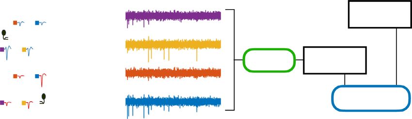
Fig. 8 Methods for in vitro measurements of Neuropixels function. a The probe is immersed in saline, with two annular electrodes producing an electric
gradient along the shank. b Equivalent circuit model to understand signal and noise pooling for one wire of the array. c Measurements of noise only without
an external field. RMS noise as a function of the saline concentration under three conditions of the switches: split recording from Bank 0, split recording
from Bank 1, and pooled recording from both. Examples of two different wires, one with high, the other with low amplifier noise Namp. d The noise at the
highest saline concentration, recording from electrode 1 vs electrode 0. Each dot is for one of the 383 wires. This limiting noise is identical across the two
electrodes on the same wire. e Histograms of the best-fit circuit parameters derived for each of the 383 wires on a pristine Neuropixels probe. RS is too
large to be measured properly.
Control of Neuropixels switching circuitry. The Neuropixels 1.0 probe has 960 proportions. For each of the 15 recording conditions (5 concentrations × 3 switch
recording sites that can be connected to 384 wires via controllable switches. The settings) we measured the root-mean-square noise on each of the 383 wires. Then
conventional mode of operation (split mode) was to connect one electrode to one we set to explain these 5 × 3 × 383 noise values based on the input circuitry of the
wire at a time. Electrode pooling was implemented by modifying the Neuropixels Neuropixels device. After some trial-and-error we settled on the equivalent circuit
API and the GUI software SpikeGLX to allow connecting up to three electrodes to in Fig. 8b. It embodies the following assumptions:
each readout wire.
● Each electrode is a resistor Ri in series with a capacitor Ci. The resistor is
entirely the bath resistance, so it scales inversely with the saline
Neuropixels device measurements. To characterize signal and noise pooling on concentration.
the Neuropixels 1.0 array, we immersed the probe in a saline bath containing two ● The shunt impedance ZS across the amplifier input is a resistor RS in
annular electrodes to produce an electric field gradient (Fig. 8a). The electrolyte parallel with a capacitor CS.
was phosphate-buffered saline (Sigma-Aldrich P4417; 1× PBS contains 0.01 M ● The thermal noise from this R-C network and the voltage noise Namp from
phosphate buffer, 0.0027 M potassium chloride and 0.137 M sodium chloride, pH the amplifier and acquisition system sum in quadrature.
7.4, at 25 ∘C). We recorded from all 383 wires (recall that one wire is a reference
With these assumptions, one can compute the total noise spectrum under each
electrode), first closing the switches in Bank 0 then in Bank 1, then in both banks
condition. In brief, each resistor in Fig. 8b is modeled as a white-spectrum Johnson
(Fig. 3b).
noise source in series with a noiseless resistor (Thevenin circuit). The various
One set of measurements simply recorded the noise with no external field
Johnson noise spectra are propagated through the impedance network to the
applied. Then we varied the concentrations of PBS (by factors 10−3, 10−2, 10−1, 1,
output voltage U. That power spectrum is integrated over the AP band
and 10), which modulated the conductance of the bath electrolyte in the same
NATURE COMMUNICATIONS | (2021)12:5245 | https://doi.org/10.1038/s41467-021-25443-4 | www.nature.com/naturecommunications 11ARTICLE NATURE COMMUNICATIONS | https://doi.org/10.1038/s41467-021-25443-4
(300–10,000 Hz) to obtain the total thermal noise. After adding the amplifier noise Spike-sorting. For “manual” spike-sorting of the in vivo recordings, we used
Namp in quadrature one obtains the RMS noise at the output U. This quantity is KiloSort1 (downloaded from https://github.com/cortex-lab/KiloSort on Apr 10,
plotted in the fits of Fig. 8c. 2018). We ran the automatic template-matching step; the detailed settings are
The result is rather insensitive to the electrode capacitance Ci because that available in the code accompanying this manuscript. This was followed by manual
impedance is much lower than the shunt impedance ZS. By contrast, the bath curation, merging units, and identifying those of high quality. These manual
resistance (R0, R1) has a large effect because one can raise it arbitrarily by lowering judgments were based on requiring a plausible spike waveform with a footprint
the saline concentration. To set the capacitor values, we, therefore, used the over neighboring electrodes, a stable spike amplitude, and a clean refractory period.
information from the Neuropixels spec sheet that the total electrode impedance at This was done separately for each of the three recordings (split-mode Bank 0, split-
1 kHz is 150 kΩ, mode Bank 1, pooled-mode).
We implemented the “hot sorting” feature in KiloSort2 (downloaded from
1 https://github.com/MouseLand/Kilosort2 on Mar 19, 2020). No manual curation
Ci ¼ qffiffiffiffiffiffiffiffiffiffiffiffiffiffiffiffiffiffiffiffiffiffiffiffiffiffiffiffiffiffi ð12Þ
2π 1000 Hz ð150kΩÞ2 Ri 2 was used in this mode, because (1) we wanted to generate a reproducible outcome,
and (2) manual inspection is out of the question for the high-volume recordings
We also found empirically that the shunt impedance is primarily capacitive: RS where electrode pooling will be applied. We first sorted the two split-mode
is too large to be measured properly and we set it to infinity. Thus the circuit model recordings and used their templates to initialize the fields W and U of rez2 before
has only 4 scalar parameters: R0, R1, CS, Namp. Their values were optimized running the main template-matching function on the pooled recording (see the
numerically to fit all 15 measurements. This process was repeated for each of the accompanying code for more details). Finally, the splits, merges, and amplitude
383 wires. The fits are uniformly good; see Fig. 8c for examples. cutoffs in Kilosort2 ensured that the final output contained as many well-isolated
As expected the thermal noise increases at low electrolyte concentration because units as possible. We then selected cells designated as high quality (KSLabel of
the bath impedance increases (Fig. 8c). However, the noise eventually saturates far Good) by KiloSort2, indicating putative, well-isolated single neurons35.
below the level expected for the lowest saline concentration. This reveals the To elaborate on the internal operations of Kilosort2: Spike-sorted units were
presence of another impedance in the circuit that acts as a shunt across the first checked for potential merges with all other units that had similar multi-
amplifier input (Fig. 2a). We found that ZS ≈ 20 MΩ. Because the shunt impedance channel waveforms (waveform correlation >0.5). If the cross-correlograms had a
far exceeds the electrode impedances2 (~150 kΩ), it has only a minor effect on large dip (0.9 were good matches.
U P ¼ c0 V 0 þ c1 V 1 ð15Þ
Estimating pooling coefficients in vivo. Once each P 2 P was assigned a match
The Ui differ from the Vi only by the ratio of electrode impedance to shunt
S 2 S, the pooling coefficient (k) was computed by solving the optimization pro-
impedance. Given the measured value of ZS ≈ 20 MΩ that ratio isYou can also read