Fe7S8/N-doped Graphene Foam Composite as Efficient Bifunctional Electrocatalysts for Overall Water Splitting
←
→
Page content transcription
If your browser does not render page correctly, please read the page content below
Int. J. Electrochem. Sci., 16 (2021) Article ID: 210433, doi: 10.20964/2021.04.58

 International Journal of
 ELECTROCHEMICAL
 SCIENCE
 www.electrochemsci.org

Fe7S8/N-doped Graphene Foam Composite as Efficient
Bifunctional Electrocatalysts for Overall Water Splitting
Xin Huang, Shuliang Wang*, Xueli Zhang, Li Liu

School of New Energy and Materials, Southwest Petroleum University, Xindu Avenue 8#, Sichuan
610500, China
*
 E-mail: wsliang1465@126.com

Received: 5 January 2021 / Accepted: 3 February 2021 / Published: 28 February 2021

Exploring and developing efficient and stable bifunctional electrocatalysts for overall water splitting is
of great importance to alleviate the serious consumption of fossil energy sources. Herein, nano-
constructed iron sulfide loaded on N-doped graphene foam (Fe7S8/NGF) was obtained by hydrothermal
process and chemical vapor deposition (CVD) and used as a highly efficient electrocatalyst for HER
(hydrogen evolution reaction) and OER (oxygen evolution reaction). The graphene foam with a three-
dimensional porous structure not only improves the overall conductivity of the catalyst but also
facilitates the in-situ growth of Fe7S8 nanoparticles and exposes more active sites, thereby optimizing
mass and electron transfer. Therefore, the synergistic effect of transition metal sulfide and NGF has
greatly enhanced its catalytic performance. In 1 M KOH, Fe7S8/NGF bifunctional electrocatalyst has
excellent HER (197.8 mV, 10 mA·cm−2) and OER (450 mV, 100 mA·cm−2) catalytic ability as well as
highly stability for long-term operation. Moreover, the Fe7S8/NGF catalyst exhibits excellent ability for
overall water splitting, reaching a current density of 100 mA·cm−2, requires an additional applied voltage
of 2.21 V only, and maintains good stability during 12 hours of continuous work.

Keywords: Bifunctional electrocatalysts; Iron sulfide; N-doped graphene foam; Hydrothermal
process; Chemical vapor deposition.

1. INTRODUCTION

 At present, humans are confronted with an increasingly severe energy crisis. Thus, renewable
and environment-friendly alternative energy sources should be developed. Among numerous conversion
systems and energy storage, an ideal electrolytic water technology has been favored by scholars and
widely studied[1]. Water electrolysis includes two half reactions, namely, hydrogen evolution reaction
(HER) and oxygen evolution reaction (OER). OER remains a challenging research direction because of
its slow thermodynamic process and large overpotential[2]. Therefore, developing a catalyst with high
catalytic activity, good stability, and appropriate cost for large-scale industrialization of decomposed
Int. J. Electrochem. Sci., 16 (2021) Article ID: 210433 2

water is of great importance[3]. Platinum (Pt) and noble metal oxides, such as IrO2 and RuO2, are highly
efficient and considered state-of-the-art HER and OER catalysts. However, these noble metal catalysts
are unfavorable for practical applications because of their scarcity and high cost[4, 5].
 Researchers have explored and studied a variety of electrocatalysts, such as transition metal-
based materials (chalcogenide[6, 7], phosphides[8], boride[9], and metal oxide/hydroxide[10-12]), and
metal-free catalysts[13, 14]. Compared with other transition metal-based compounds, iron-based
materials are advantageous for electrocatalytic applications[15-17] because iron is the second most
abundant metal in the Earth’s crust and has the lowest toxicity. Fe-S clusters are active centers of
enzymes that catalyze some important biological reactions in nature. Iron sulfide has been reported as a
high-efficiency electrocatalyst[16, 18] but not as a bifunctional electrocatalyst because its catalytic
activity and stability are not as good as catalysts based on precious metals and other transition metals.
the number of active sites are greatly reduced due to the inherent stacking and aggregation properties of
individual transition metal sulfides[19]. To solve the above problems, scholars have developed an
effective method that combines transition metal sulfides with three-dimensional carbon additives to not
only reduce the stacking and expose more active sites but also enhance the conductivity of the
electrocatalyst[20, 21]. Ling et al.[22] loaded Co1.097S nanoparticles on graphene foams to achieve
excellent activity for water splitting. The current density of 10 mA·cm−2 in OER and HER only requires
overpotentials of 240 and 124 mV, respectively. Similarly, Zhao et al.[23] loaded MoS2 nanosheets onto
graphene aerogels to expose more active sites and enhance their HER catalytic capability.
 Inspired by the above research, the present work fabricated Fe-S/NGF electrocatalysts by loading
Fe-S nanoparticles on NGF. The carbon atoms in the lattice are replaced by nitrogen atoms in the
conductive carbon substrate doped with nitrogen atoms, and sp2 hybridization is destroyed. Nitrogen
atoms with more negative charge give electrons to the system, thereby promoting the adsorption of
intermediates on the surface of the electrocatalyst and the electron transfer during the catalytic
reaction[24, 25]. In addition, the doping of N atoms inevitably introduces some inherent defects, such as
point defects or disordered structures, which are beneficial to enhance the catalytic activity[26]. The
unique three-dimensional structure greatly increases the contact area with the electrolyte and exposes
more active sites.

2. EXPERIMENTAL

2.1 Materials

 All chemicals were of analytical grade unless otherwise specified. Deionized water was used
throughout the tests. Graphene oxide power was provided by Nanjing XFNano Material Tech Co., Ltd.
(Nanjing, China). CH4N2S (Thiourea), Fe(NO3)3·9H2O, C2H6O (Ethanol), and CH4N2O (Urea) were
purchased from Chron Chemicals Co., Ltd. (Chengdu, China). Nafion solution (5 wt.%) was provided
by DuPont, China.
Int. J. Electrochem. Sci., 16 (2021) Article ID: 210433 3

2.2 Synthesis of electrocatalysts

 Catalyst precursor was synthesized by hydrothermal method and sulfurized by chemical vapor
deposition to obtain the target sample Fe-S/NGF-600. In brief, 0.15 g of graphene oxide powder was
immersed in 30 ml of deionized water and sonicated for several hours until a uniform suspension was
formed. The suspension was added with 2.25 mmol urea (AR) and 1.125 mmol Fe(NO3)3·9H2O (AR)
and stirred for several minutes. The above suspension was placed into a 50 ml Teflon-lined stainless
steel autoclave reactor and reacted at 180 °C for 12 h. After cooling to room temperature, the sample
was collected, cleaned several times with deionized water, and freeze dried. Thiourea and the as-prepared
sample were placed at the upstream and downstream sides of the furnace, respectively, and the mass
ratio of thiourea to sample was 6:1. The tube furnace was controlled at 600 °C for 2 h with argon flow
to obtain Fe-S/NGF-600. Figure 1 shows the schematic of the sample preparation.

 Figure 1. Synthesis of Fe-S/NGF composite

 The samples were subjected to calcination temperatures of 400 °C and 800 °C to prepare Fe-
S/NGF-400 and Fe-S/NGF-800 for comparison. Two other samples (Fe-S/NGF and Fe-S) were
synthesized for comparison. Fe-S/NGF was prepared by two-step hydrothermal method. First, 0.25 g of
graphene oxide powder was immersed in 50 ml of deionized water and sonicated for several hours to
form homogeneous dispersion suspension. The suspension was then added with 0.6 g of urea under
continuous stirring for 10 min. The prepared suspension was transferred into a 100 ml Teflon-lined
stainless steel autoclave reactor and reacted at 180 °C for 12 h. After the furnace was cooled to room
temperature, the sample was collected, cleaned several times with deionized water, and freeze dried. The
sample was placed in a tube furnace and calcined at 800 °C for 2 h under an argon atmosphere to obtain
nitrogen-doped graphene foam (NGF). Second, 4.375 mmol thiourea and 2.625 mmol Fe(NO3)3·9H2O
were added into 70 ml of ethanol under stirring to form a homogeneous solution. The solution along
with NGF was transferred into a 100 ml Teflon-lined stainless steel autoclave and reacted at 180 °C for
12 h. After the furnace was cooled to room temperature, the product was cleaned with deionized water
for several times and dried in a vacuum oven at 60 °C. Fe-S was synthesized by the same process as Fe-
S/NGF without the presence of NGF.
Int. J. Electrochem. Sci., 16 (2021) Article ID: 210433 4

2.3 Characterization

 The composition and surface morphology of the synthesized samples were characterized by
scanning electron microscope (ZEISS EV0 MA15, Germany) equipped with energy dispersive
spectrometer (EDS) at an acceleration voltage of 20 kV. Phase structures were analyzed using XRD
(Bruker D8 advance) with Cu Kα radiation (λ=0.154056 nm). The element composition and valence of
the sample was analyzed through X-ray photoelectron spectroscopy (XPS) using Thermo ESCALAB
250XI with efficiency and energy voltage of 12 kV, vacuum degree during sputtering of 2.0 × 10⁻⁷ mbar,
and Mg Kα target as the radiation source.
 The electrochemical performance of the samples was tested in 1 M KOH solution at room
temperature by using a Gmary Reference 3000 workstation. A classical three-electrode system was
adopted with Ag/AgCl electrode as the reference electrode, Pt as the counter electrode, and sample
directly coated on the nickel foam as the working electrode. The working electrode was prepared by
adding 5 mg of the catalyst powder and 40 μl of Nafion (5 wt%) in 1 ml of ethanol. The mixed suspension
was sonicated for 30 min to form a homogeneous ink. The ink was dropped onto the precleaned nickel
foam (1 cm × 1 cm) with a catalyst loading of ~ 5 mg·cm−2 and dried at room temperature. Linear sweep
voltammetry (LSV) was performed on each group of samples to analyze and compare the catalytic
performance of different samples. All applied potentials were converted with respect to reversible
hydrogen electrode (RHE) by using the following formula:
 ERHE=EAg/AgCl+0.059·pH+EϴAg/AgCl
 where, EAg/AgCl is the applied potential versus Ag/AgCl electrode, EϴAg/AgCl is the standard
potential of Ag/AgCl electrode (0.199 V), and ERHE is the converted potential versus RHE.
 LSV test was performed at a scan rate of 5 mV·s−1 in 1.0 M KOH electrolyte (pH 14). Electric
impedance spectroscopy (EIS) analysis was carried out at the overpotential of 300 mV in 1.0 M KOH
with the frequency range of 100 kHz to 0.1 Hz and 5 mV amplitude sinusoidal voltage as disturbance
signal. Cyclic voltammetry (CV) test was adopted to calculate dynamic parameter C dl (double-layer
capacitance) within the scan range of 0.1–0.2 V (vs. Ag/AgCl) with different scanning rates (20, 40, 60,
80, 100, and 120 mV·s−1). Chronopotentiometry analysis was performed at a constant current density of
100 mA·cm−2 for 43200 s to characterize the stability of the electrodes.

3. RESULTS AND DISCUSSION

3.1 Morphology and composition analyses

 The SEM images of Fe-S/NGF-600, bare NGF, bare Fe-S, Fe-S/NGF-400, Fe-S/NGF-800, and
Fe-S/NGF are shown in Figure 2. Based on Figure 2(a), the Fe-S/NGF-600 sample has a three-
dimensional porous structure with uniform pore size (about 7 µm). Zhou et al.[27] stated that porous
graphene materials have large specific surface area and high porosity, which are of great significance
for enhancing electrolyte–electrode interaction and electrolyte reactant diffusion. Figure 2(b) presents
the SEM image of Fe-S/NGF-600 with higher magnification. A large number of nanoparticles are
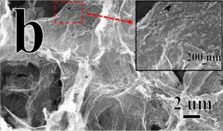
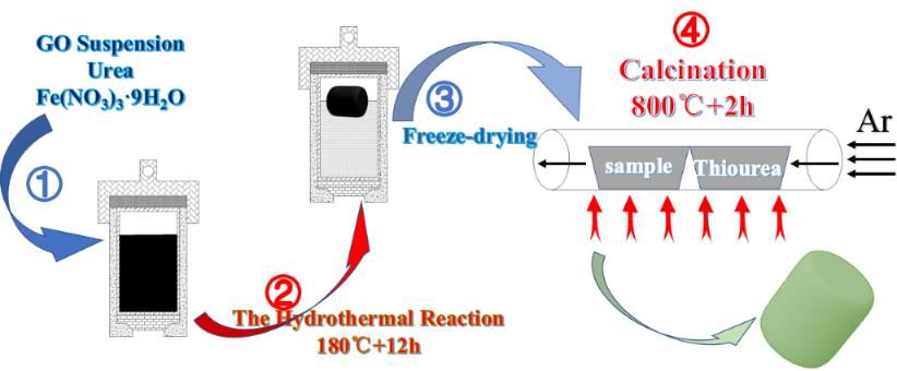
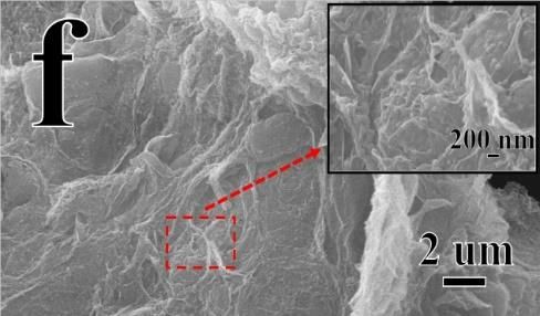
Int. J. Electrochem. Sci., 16 (2021) Article ID: 210433 5

uniformly distributed on the surface of NGF. Figure 2(b) demonstrates a partially enlarged view to better
observe the morphology of nanoparticles. The size of nanoparticles is uniform and about 90 nm. Yang
et al.[28] reported that nanostructures can increase the specific surface area, adjust the electronic
structure and hybridization to accelerate charge transfer, and optimize the binding energy between the
catalyst and reaction intermediates.

Figure 2. SEM images of the samples: a-b) Fe-S/NGF-600, c) bare NGF, d), bare Fe-S, (e-f) Fe-S/NGF-
 400, (g-h) Fe-S/NGF-800, and (i-j) Fe-S/NGF. Illustrations in all SEM images are partially
 enlarged. Image k is the representative EDS mapping of the sample Fe-S/NGF-600.
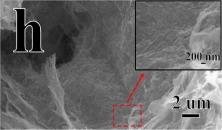
Int. J. Electrochem. Sci., 16 (2021) Article ID: 210433 6

 Figure 2(c) shows the bare NGF, which presents a porous three-dimensional structure and micro
morphology comprising interlaced sheets. In the absence of the NGF substrate, Fe-S particles aggregate
seriously and their size is uneven [Figure 2(d)]. The size of iron sulfide nanoparticles is about 1 µm,
which is larger than that of Fe-S/NGF-600 [Figure 2(d)]. This morphology greatly reduces the contact
area between the electrolyte and electrode, thereby affecting its catalytic performance. Figures 2(e-f) and
2(g-h) show the micro morphologies of Fe-S/NGF-400 and Fe-S/NGF-800, respectively, which are
similar to that of Fe-S/NGF-600. This finding is because the three groups of samples were prepared
under the same hydrothermal conditions. The carbon substrate of Fe-S/NGF is flaky, and its three-
dimensional structure is not obvious [Figure 2(i-j)]. The distribution of iron sulfide particles on the
surface of Fe-S/NGF is uneven, and the size of particles varies greatly. Figure 2(k) displays the EDS
mapping images of Fe-S/NGF-600. Fe, S, C, N, and O are uniformly distributed in the sample, indicating
that Fe-S nanoparticles are uniformly covered on the surface, and N atoms are also doped into the sample.
 The atomic percentages of different elements were obtained by EDS (Table 1). The content of N
atom in Fe-S/NGF-600 is the highest, which indicates that more N atoms are doped in this sample. The
content of S atom in Fe-S/NGF-400 is lower than that of Fe atom, while the atomic ratio of S to Fe in
Fe-S/NGF-600 and Fe-S/NGF-800 is close to 1:1. This finding indicates that 600 °C is the best
temperature to introduce S and N. Liu et al.[26] hypothesized that temperature may affect the doping of
N atoms.

Table 1. Atomic percentages of different elements

 N (%) S (%) Fe (%)
 Fe-S/NGF-400 0.97 3.05 11.38
 Fe-S/NGF-600 4.37 6.61 7.35
 Fe-S/NGF-800 1.02 11.78 12.19

 Figure 3. XRD patterns of Fe-S/NGF, Fe-S/NGF-400, Fe-S/NGF-600, and Fe-S/NGF-800
Int. J. Electrochem. Sci., 16 (2021) Article ID: 210433 7 Figure 3 shows the X-ray diffraction (XRD) patterns of the samples. Carbon peaks and iron compounds are present in the four groups of samples, indicating the successful preparation of composite products of iron compounds and carbon substrate. The intensity of the carbon peak (2θ = 26.6°) of Fe- S/NGF (Figure 3) is significantly higher than that of samples prepared by CVD vulcanization. This finding indicates the uneven coverage of iron sulfide nanoparticles on the surface of the carbon substrate in Fe-S/NGF. Meanwhile, in the three other groups of samples prepared by CVD vulcanization, the coverage of iron sulfide nanoparticles on the surface of the carbon substrate is uniform, so the intensity of the carbon peak is lower. This result is consistent with the SEM analysis. Fe2O3 and FeS2 appear simultaneously in Fe-S/NGF samples because only part of iron is sulfurized by hydrothermal vulcanization, leading to the poor catalytic performance of Fe-S/NGF. The XRD spectrum of Fe-S/NGF- 400 has no iron sulfide but only Fe2O3 because the temperature is too low and the precursor is not successfully vulcanized by CVD. Nevertheless, the XRD results indicate the successful preparation of Fe7S8 and graphene foam composites in Fe-S/NGF-600 and Fe-S/NGF-800 samples. The diffraction peaks at 30.03, 33.99, 43.99, and 53.33 could be indexed to the (200), (203), (206), and (220) planes of Fe7S8 (PDF# 76-2308) with a hexagonal crystal structure. Chen et al.[18] reported that Fe7S8 has excellent electrocatalytic properties. XPS analysis was carried out to further investigate the composition and chemical bonding states of the samples. Figure 4 shows the XPS spectra of Fe-S/NGF-600. The XPS spectrum demonstrates the presence of S, C, O, Fe, and N in Fe-S/NGF-600 [Figure 4(e)]. Figure 4(a) shows the high-resolution XPS spectrum of Fe 2p and presents the diffraction peaks of Fe 2p3/2 and Fe 2p1/2. The peaks at binding energy levels of 721.4, 712.3, and 707.9 eV correspond to Fe2+, and those at 725.0 and 710.7 eV are assigned to Fe3+[29]. In the high-resolution XPS spectrum of S 2p [Figure 4(b)], the peaks with binding energy levels of 164.2, 162.6, and 161.5 eV correspond to S2−, while the peak at 167.8 eV may be due to the formation of SO32− on the surface of Fe7S8 nanoparticles by oxidation in air[29]. Figure 4(c) presents the high-resolution XPS spectrum of C 1s, which contains four peaks at 284.3, 285.0, 286.1, and 288.4 eV, corresponding to C-C/C=C bond, C-N bond, C-O bond, and C = O bond, respectively[5]. The strength of C-O bond and C=O bond is very weak. The majority of oxygen functional groups are eliminated when vulcanization is carried out at 600 °C, which is more conducive to the incorporation of N atoms in the three-dimensional graphene foam[30]. According to the high-resolution XPS spectrum of N 1s [Figure 4(d)], the doping forms of N are pyrrolic N (399.4 eV), graphitic N (401.6 eV), and pyridinic N (398.2 eV). Nitrogen doping cannot only provide more active centers for graphene but also enhance the interaction between the carbon matrix and catalytic materials[31, 32], thereby optimizing the electron transfer kinetics in the samples. Pyridinic N can increase the number of electrocatalytic active sites in graphene, and graphite N can improve the conductivity of graphene[30, 33]. The XPS analysis results indicate the existence of Fe2+, Fe3+, and S2− bonds, confirming the formation of metal sulfides in the sample. The results are consistent with the XRD data.
Int. J. Electrochem. Sci., 16 (2021) Article ID: 210433 8

Figure 4. XPS spectra of Fe-S/NGF-600: a–d) high-resolution XPS spectra of a) Fe 2p, b) S 2p, c) C 1s,
 and d) N1s; and e) full-scan spectra

3.2 Electrocatalytic performance

 Figures 5(a-b) show the LSV test results of the samples. The overpotential of Fe-S/NGF-600 and
Fe-S/NGF-400 to reach the current density of 10 mA·cm−2 is 197.8 mV, which is lower than those of
Fe-S/NGF-800 (202.11 mV, 10 mA·cm−2), Fe-S/NGF (207.92 mV, 10 mA·cm−2), Fe-S (213.86 mV, 10
mA·cm−2), and NGF (251.99 mV, 10 mA·cm−2). This finding may be due to the high vulcanization
temperature, which is not conducive to the doping of nitrogen atoms, resulting in slightly higher HER
overpotential of Fe-S/NGF-800 than that of Fe-S/NGF-600. The result is consistent with the EDS data.
According to the results of XRD, the overpotential of Fe-S/NGF is higher than that of Fe-S/NGF-600.
The synthesis of Fe-S/NGF leads to the fact that iron sulfide is partially formed and the rest is iron oxide.
The SEM results show that the three-dimensional structure of the carbon substrate is not obvious, and
the distribution of nanoparticles on the surface is less and extremely uneven, leading to poor
performance. The catalytic activity of Fe-S/NGF-600 for HER is higher than that of bare Fe-S and bare
NGF, indicating that the composite of iron sulfide nanoparticles and the conductive matrix can
effectively improve the catalytic performance.
 The kinetics of HER was also studied using Tafel slope [Figures 5(c)]. The Tafel slope of Fe-
S/NGF-600 is 79.2 mV·dec−1, which is lower than those of Fe-S/NGF-400 (86.2 mV·dec−1), Fe-S/NGF-
800 (86.3 mV·dec−1), Fe-S/NGF (89.3 mV·dec−1), Fe-S (116.3 mV·dec−1), and NGF (174.1 mV·dec−1).
Hence, Fe-S/NGF-600 has the fastest kinetics of hydrogen generation. The three main pathways of HER
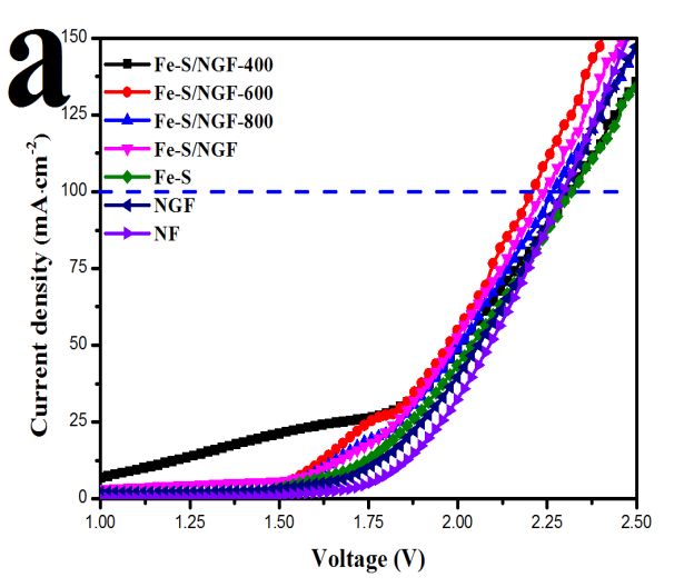
Int. J. Electrochem. Sci., 16 (2021) Article ID: 210433 9

in alkaline environment are as follows[34, 35]. First, the H atom is adsorbed on the active site of the
catalyst to form an adsorption intermediate [Volmer reaction with a Tafel slope of 120 mV·dec−1 (H2O
+ M + e− = M–Hads + OH−, water discharge step)]. Subsequently, H2 is produced by Heyrovsky reaction
with a Tafel slope of 40 mV·dec−1 (M–Hads + H2O + e− = M + H2 + OH−, electrochemical desorption
step) or Tafel reaction with a Tafel slope of 30 mV·dec−1 (2M–Hads = 2M + H2, chemical recombination
step). In the above equations, M and Hads represent the active center of the catalyst and the hydrogen
atom adsorbed on the active center, respectively. The Tafel slope of Fe-S/NGF-600 is 79.2 mV·dec−1,
indicating that the reaction pathway of HER is Volmer–Heyrovsky, and the rate control step is water
discharge. Figure 5(d) shows the stability test results of Fe-S/NGF-600 under the condition of current
density of 100 mA·cm−2 for 12 h. The finding shows the excellent stability of the sample.

Figure 5. a) Polarization curves of the samples for HER at a scan rate of 5 mV·s −1 in 1 M KOH. b)
 Corresponding overpotentials (10 mA·cm−2). c) Corresponding Tafel slopes. (d)
 Chronopotentiometry curves of the Fe-S/NGF-600 for HER under a constant current density of
 100 mA cm−2.

 Figure 6 shows the results of the OER measurements. The current density of Fe-S/NGF-600 is
higher than those of the other catalysts at a given potential. Fe-S/NGF-600 only requires an overpotential
(η100) of 450 mV, which is remarkably lower than those of Fe-S/NGF-400 (488 mV), Fe-S/NGF-800
(478 mV), Fe-S/NGF (494 mV), Fe-S (488 mV), and NGF (478 mV) to deliver a current density of 100
mA·cm−2 [Figures 6(a-b)]. Fe-S/NGF-600 has the best catalytic performance among all CVD
vulcanization samples because iron sulfide is not formed at 400 °C, while N atom doping is not favorable
Int. J. Electrochem. Sci., 16 (2021) Article ID: 210433 10

at 800 °C, resulting in poor catalytic performance of the two groups of OER. In addition, the performance
of Fe-S/NGF-600 is better than that of the bare Fe-S and the bare NGF, indicating that the combination
of iron sulfide nanoparticles and the conductive matrix can greatly improve the catalytic performance
for OER. The catalytic performance of Fe-S/NGF-600 is better than that of Fe-S/NGF. The unique three-
dimensional porous structure and the uniformly distributed transition metal nanoparticles on the surface
can increase the surface area in contact with the electrolyte and the number of active sites, thereby
improving its catalytic performance. The pathway of OER in alkaline environment is as follows[27]:
 M + OH− → M–OH + e−
 M–OH + OH− → M–O + H2O + e−
 2M–O → 2M + O2
 Or M–O + OH− → M–OOH + e−
 M–OOH + OH− → M + O2 + H2O + e−
 First, OH− is adsorbed on the surface of the catalyst (M) to form adsorption intermediate M–OH,
and an electron is transferred to the electrode surface at the same time. Then, M–OH combines with
another OH− to transform into adsorption intermediate M–O and transfers an electron to the electrode
surface. The conversion of M–O to oxygen follows two possible pathways. The first pathway is two M–
O molecules adsorbed on the electrode directly combined to form oxygen molecules. The second one is
the reaction of M–O with OH− to form a new adsorption intermediate M–OOH, which then reacts with
OH− to produce oxygen molecules. In general, the thermodynamic barrier of the second pathway is
always smaller than the first pathway[1, 27].

Figure 6. a) Polarization curves of the samples for OER at a scan rate of 5 mV·s −1 in 1 M KOH. b)
 Corresponding overpotentials (100 mA·cm−2). c) Corresponding Tafel slopes. (d)
 Chronopotentiometry curves of the Fe-S/NGF-600 for OER under a constant current density of
 100 mA cm−2.
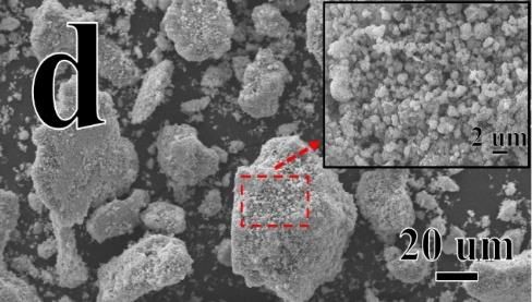
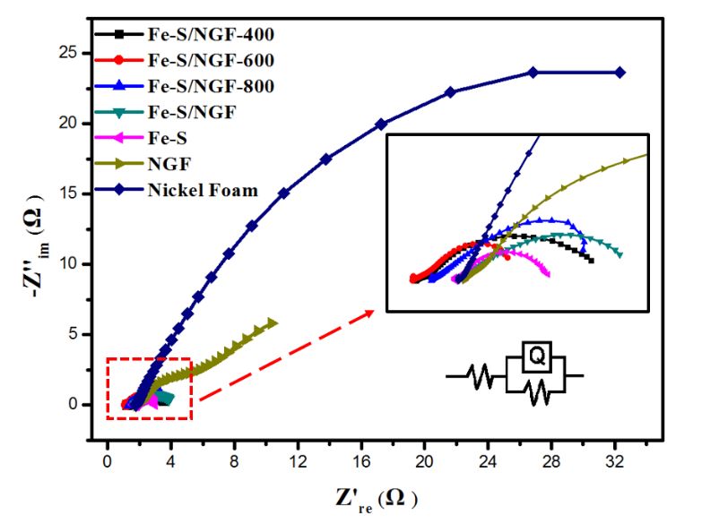
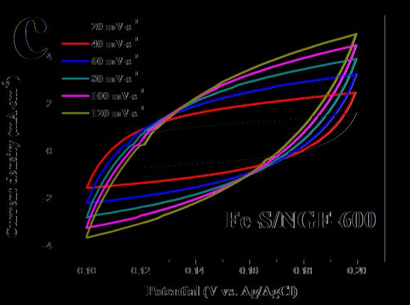
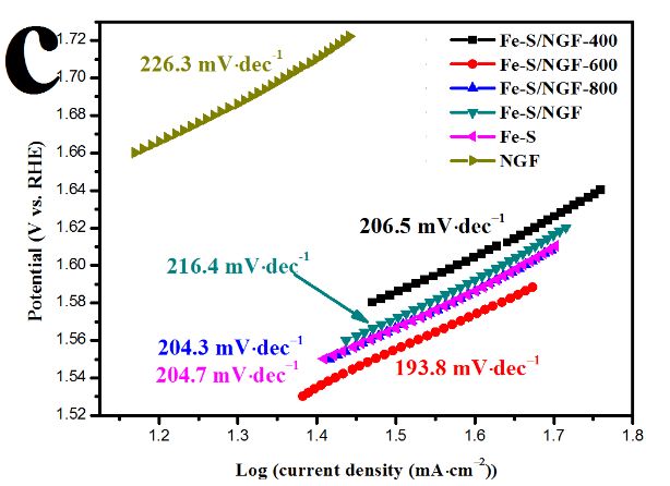
Int. J. Electrochem. Sci., 16 (2021) Article ID: 210433 11

 Figure 6(c) compares the Tafel slopes of the samples to further analyze the mechanism. The Tafel
slope of Fe-S/NGF-600 is 193.8 mV∙dec−1, which is smaller than those of Fe-S/NGF-400, Fe-S/NGF-
800, Fe-S/NGF, Fe-S, and NGF. Hence, Fe-S/NGF-600 has better electrocatalytic kinetics. Figure 6(d)
shows the chronopotentiometry curve of Fe-S/NGF-600 measured under a constant current density of
100 mA∙cm−2. The potential of Fe-S/NGF-600 only changes slightly after 12 h, indicating that it has
excellent stability.
 The CV curves of Fe-S/NGF-600, Fe-S, and NGF at different scanning rates are shown in Figure
7(a-c). Figure 7(d) shows the linear relationship diagram of current Δj at different scanning rates (20,
40, 60, 80, 100, and 120 mV∙s−1) within a certain voltage range (0.1 – 0.2 V vs. Ag/AgCl), and half of
the slope is the value of Cdl. According to the linear relationship diagram, the Cdl of Fe-S/NGF-600 is
14.56 mF∙cm−2, which is higher than those of Fe-S and NGF. This result indicates that Fe-S/NGF-600
has larger electrochemical active surface area (ESCA) than the other samples. A large ESCA is a
characteristic of a nano-array structure catalyst[3].

Figure 7. Typical cyclic voltammogram (CV) curves of a) NGF, b) Fe-S, and c) Fe-S/NGF-600 in 1 M
 KOH with different scan rates. d) Differences in current density of NGF, Fe-S, and Fe-S /NGF
 plotted against scan rates.

 Figure 8 shows the Nyquist plots of the samples measured at the overpotential of 300 mV in 1.0
M KOH. The intercept between the semicircle and the real axis corresponds to solution resistance (Rs)
in the equivalent circuit diagram because of the ionic resistance of the electrolyte. A low Rs indicates
Int. J. Electrochem. Sci., 16 (2021) Article ID: 210433 12

excellent conductivity. As shown in Table 2, Fe-S/NGF-600 has the lowest electrolyte resistance; thus,
the desorption and adsorption of oxygen on the Fe-S/NGF-600 surface are more likely to occur[36]. This
result is consistent with the previous OER catalytic performance analysis. The diameter of the semicircle
is related to the charge transfer resistance (Rct) caused by redox reaction on the electrode surface. Fe-
S/NGF-600 has a small Rct (2.56 Ω∙cm−2), which indicates that the electrode has good conductivity in
the reaction[37].

Figure 8. a) Nyquist plots of EIS with an overpotential of 300 mV in 1 M KOH. The insets are the
 equivalent model and the partial enlargement.

 Electrochemical active surface area (ESCA) can be calculated from the capacitance of the double
layer (Cdl) by the following formula[38]:
 1
 = ( −1 −1 1− )
 ( + )
 ESCA can be obtained by dividing the double-layer capacitance by CS (CS is the specific
capacitance of a flat surface of the electrode material within 20–60 µF∙cm−2[28]. In the present study,
the test was conducted in 1 M KOH, so the CS is equal to 40 µF∙cm−2[22]). In Table 2, Fe-S/NGF-600
has the largest surface active area, which is consistent with the previous CV test results.
Int. J. Electrochem. Sci., 16 (2021) Article ID: 210433 13

 Table 2. Element equivalent circuit parameters

 Rs Q n Rct Cdl ECSA
 Samples
 (Ω·cm−2) (Ω ·cm−2·s−1)
 −1
 (Ω·cm−2) (uF·cm−2) (cm2)
Fe-S/NGF-400 1.252 0.1459 0.5917 2.73 36053.1 901.33
Fe-S/NGF-600 1.189 0.49 0.5143 2.56 202095.3 5052.38
Fe-S/NGF-800 1.431 0.234 0.5624 3.45 73124.8 1828.12
 Fe-S/NGF 1.767 0.205 0.5583 2.89 66323.3 1658.08
 Fe-S 1.743 0.1582 0.7639 1.26 81182.4 2029.56
 NGF 1.812 0.07828 0.5115 21.86 11234.9 280.87

 The performance of Fe-S/NGF-600 as electrocatalyst for overall water splitting was studied. A
 two-electrode system was used, and Fe-S/NGF-600 was directly used as anode and cathode. Figure 9(a)
 shows the LSV test results of the sample in 1 M KOH solution with the scanning rate of 5 mV∙s −1 and
 the scanning range of 0.5–2.5 V.

 Figure 9. a) Polarization curves of two-electrode overall water splitting by using the prepared catalysts
 on nickel foam (NF) as anode and cathode at a scan rate of 5 mV∙s-1 in 1 M KOH. b)
 Chronopotentiometry response of Fe-S/NGF-600 carried out at 100 mA∙cm−2 current density.

 As shown in Figure 9(a), Fe-S/NGF-600 has the best catalytic performance, and the current
 density of 100 mA∙cm−2 can be obtained by applying 2.21 V. The stability of the samples was also tested
 by chronopotentiometry [Figure 9(b)]. Fe-S/NGF-600 has excellent stability for long-term operation.
Int. J. Electrochem. Sci., 16 (2021) Article ID: 210433 14

Table 3. Comparison of overpotential (η) for OER and HER of transition metal-based electrocatalysts,
 namely, Pt/C and RuO2, in 1 M KOH alkaline electrolyte.

 Electrocatalyst HER (mV) OER (mV) Reference
 Fe7S8/NGF 197.8 (η10) 450 (η100) this work
 RuO2 / 340 (η10) [39]
 Pt/C 56 (η10) / [21]
 NiCo2O4 / 457 (η100) [40]
 CoP–N / 450 (η10) [8]
 NixSy/NGF 193 (η10) 311 (η10) [21]
 Co9S8 HNSs 267 (η10) 342 (η10) [41]
 CoP 159 (η10) 400 (η10) [42]
 CoxFe3−xO4 / 420 (η10) [43]
 3D Nickel / 496 (η50) [44]
 FeSe2 / 500 (η70) [45]

 Table 3 summarizes the overpotentials of some transition metal-based electrocatalytic materials,
namely, Pt/C and RuO2, reported in literature. Fe7S8/NGF is a potential candidate as an economic and
efficient non-noble transition metal-based catalyst for OER in alkaline environment.

4. CONCLUSIONS

 Fe7S8/NGF electrocatalyst was successfully prepared by hydrothermal process and chemical
vapor deposition. The unique three-dimensional porous structure combined with iron sulfide
nanoparticles greatly increased the contact area between the catalyst and electrolyte and exposed more
active sites. The residual functional groups of the graphene foam surface were removed by high-
temperature vulcanization at 600 °C to enhance the conductivity of the electrocatalyst. In addition, N
atoms were doped to increase the number of active sites and optimize the electron transfer process. These
properties conferred Fe7S8/NGF bifunctional catalyst with excellent HER catalytic ability (197.8 mV,
10 mA∙cm−2, 1 M KOH) and OER catalytic ability (450 mV, 100 mA∙cm−2, 1 M KOH) as well as
excellent stability. The catalyst also showed excellent overall water splitting ability, reached the current
density of 100 mA∙cm−2, required only 2.21 V additional applied voltage, and maintained good stability
during 12 h of continuous operation. Hence, Fe7S8/NGF is expected to be a suitable alternative of noble
metals for electrocatalysts because of its excellent performance, abundance of earth reserves of raw
materials, simple and feasible preparation, and large-scale commercial electrolysis of water.

References

1. L.S. Peng, S.S.A. Shah, Z.D. Wei, Chin. J. Catal., 39 (2018) 1575-1593.
2. M. Sarfraz, I. Shakir, J. Storage Mater., 13 (2017) 103-122.
3. P. Guo, Y.X. Wu, W.M. Lau, H. Liu, L.M. Liu, J. Alloys Compd., 723 (2017) 772-778.
4. J.Y. Kim, J.H. Choi, H.Y. Kim, E. Hwang, H.J. Kim, S.H. Ahn, S.K. Kim, Appl. Surf. Sci., 359
Int. J. Electrochem. Sci., 16 (2021) Article ID: 210433 15

 (2015) 227-235.
5. P.Y. Kuang, M. He, H.Y. Zou, J.G. Yu, K. Fan, Appl. Catal., B, 254 (2019) 15-25.
6. Y.H. Deng, C. Ye, B.X. Tao, G. Chen, Q. Zhang, H.Q. Luo, N.B. Li, J. Power Sources, 397 (2018)
 44-51.
7. K.L. Yan, X. Shang, Z. Li, B. Dong, J.Q. Chi, Y.R. Liu, W.K. Gao, Y.M. Chai, C.G. Liu, Int. J.
 Hydrogen Energy, 42 (2017) 17129-17135.
8. L. Chen, J.T. Ren, Y.S. Wang, W.W. Tian, L.J. Gao, Z.Y. Yuan, ACS Sustainable Chem. Eng., 7
 (2019) 13559-13568.
9. M. Arivu, J. Masud, S. Umapathi, M. Nath, Electrochem. Commun., 86 (2018) 121-125.
10. Y.H. Dou, T. Liao, Z.Q. Ma, D.L. Tian, Q.N. Liu, F. Xiao, Z.Q. Sun, J.H. Kim, S.X. Dou, Nano
 Energy, 30 (2016) 267-275.
11. M.A. Ghanem, A.M. Al-Mayouf, P. Arunachalam, T. Abiti, Electrochim. Acta, 207 (2016) 177-
 186.
12. V. Gupta, S. Gupta, N. Miura, J. Power Sources, 177 (2008) 685-689.
13. S. Chen, J.J. Duan, M. Jaroniec, S.Z. Qiao, Adv. Mater., 26 (2014) 2925-2930.
14. X.W. Yu, M. Zhang, J. Chen, Y.R. Li, G.Q. Shi, Adv. Energy Mater., 6 (2016) 1501492.
15. S. Shit, S. Bolar, N.C. Murmu, T. Kuila, ACS Sustainable Chem. Eng., 7 (2019) 18015-18026.
16. X.X. Zou, Y.Y. Wu, Y.P. Liu, D.P. Liu, W. Li, L. Gu, H. Liu, P.W. Wang, L. Sun, Y. Zhang, Chem,
 4 (2018) 1139-1152.
17. Z.X. Jing, Q.Y. Zhao, D.H. Zheng, L. Sun, J.H. Geng, Q.N. Zhou, J.J. Lin, J. Mater. Chem. A, 8
 (2020) 20323-20330.
18. S.C. Chen, Z.X. Kang, X.D. Zhang, J.F. Xie, H. Wang, W. Shao, X.S. Zheng, W.S. Yan, B.C. Pan,
 Y. Xie, ACS Cent. Sci., 3 (2017) 1221-1227.
19. Y.G. Li, H.L. Wang, L.M. Xie, Y.Y. Liang, G.S. Hong, H.J. Dai, J. Am. Chem. Soc., 133 (2011)
 7296-7299.
20. L. Liao, J. Zhu, X.J. Bian, L.N. Zhu, M.D. Scanlon, H.H. Girault, B.H. Liu, Adv. Funct. Mater.,
 23 (2013) 5326-5333.
21. H.Y. Zou, B.W. He, P.Y. Kuang, J.G. Yu, K. Fan, Adv. Funct. Mater., 28 (2018).
22. H. Liang, D.G. Jiang, S. Wei, X.Y. Cao, T. Chen, B.B. Huo, Z. Peng, C.W. Li, J.Q. Liu, J. Mater.
 Chem. A, 6 (2018) 16235-16245.
23. Y.F. Zhao, X.Q. Xie, J.Q. Zhang, H. Liu, H.J. Ahn, K. Sun, G.X. Wang, CHEM-EUR J, 21 (2015)
 15908-15913.
24. H.R. Yuan, F. Yan, C.Y. Li, C.L. Zhu, X.T. Zhang, Y.J. Chen, ACS Appl. Mater. Interfaces, 10
 (2018) 1399-1407.
25. S. Umrao, T.K. Gupta, S. Kumar, V.K. Singh, M.K. Sultania, J.H. Jung, I.K. Oh, A. Srivastava,
 ACS Appl. Mater. Interfaces, 7 (2015) 19831-19842.
26. P.B. Liu, Y.Q. Zhang, J. Yan, Y. Huang, L. Xia, Z.X. Guang, Chem. Eng. J., 368 (2019) 285-298.
27. X.J. Zhou, Z.Y. Bai, M.J. Wu, J.L. Qiao, Z.W. Chen, J. Mater. Chem. A, 3 (2015) 3343-3350.
28. R. Yang, Y.M. Zhou, Y.Y. Xing, D. Li, D.L. Jiang, M. Chen, W.D. Shi, S.Q. Yuan, Appl. Catal., B,
 253 (2019) 131-139.
29. H. Zhang, Q.M. Gao, X.H. Tian, Z.Y. Li, P. Xu, H. Xiao, Electrochim. Acta, 319 (2019) 472-480.
30. Z.H. Sheng, L. Shao, J.J. Chen, W.J. Bao, F.B. Wang, X.H. Xia, ACS Nano, 5 (2011) 4350-4358.
31. M. Rahsepar, M.R. Nobakht, H. Kim, M. Pakshir, Appl. Surf. Sci., 447 (2018) 182-190.
32. S. Ratso, I. Kruusenberg, M. Vikkisk, U. Joost, E. Shulga, I. Kink, T. Kallio, K. Tammeveski,
 Carbon, 73 (2014) 361-370.
33. Y. Zhao, R. Nakamura, K. Kamiya, S. Nakanishi, K. Hashimoto, Nat. Commun., 4 (2013) 1-7.
34. X.T. Yu, M.Y. Wang, Z. Wang, X.Z. Gong, Z.C. Guo, Electrochim. Acta, 211 (2016) 900-910.
35. V. Vij, S. Sultan, A.M. Harzandi, A. Meena, J.N. Tiwari, W.G. Lee, T. Yoon, K.S. Kim, ACS
 Catal., 7 (2017) 7196-7225.
36. I. Herraiz Cardona, C. González Buch, C. Valero Vidal, E. Ortega, V. Pérez Herranz, J. Power
Int. J. Electrochem. Sci., 16 (2021) Article ID: 210433 16

 Sources, 240 (2013) 698-704.
37. L.X. Wang, Y. Li, X.C. Yin, Y.Z. Wang, L. Lu, A.L. Song, M.R. Xia, Z.P. Li, X.J. Qin, G.J. Shao,
 Int. J. Hydrogen Energy, 42 (2017) 22655-22662.
38. S.L. Wang, W.T. Li, H.S. Qin, L. Liu, Y.Y. Chen, D.H. Xiang, Int. J. Electrochem. Sci., 14 (2019)
 957-969.
39. C.T. Zhao, C. Yu, H.W. Huang, X.T. Han, Z.B. Liu, J.S. Qiu, Energy Storage Mater, 10 (2018)
 291-296.
40. S. Tiwari, S. Samuel, R. Singh, G. Poillerat, J. Koenig, P. Chartier, Int. J. Hydrogen Energy, 20
 (1995) 9-15.
41. X.Y. Ma, W. Zhang, Y.D. Deng, C. Zhong, W.B. Hu, X.P. Han, Nanoscale, 10 (2018) 4816-4824.
42. M.J. Liu, J.H. Li, ACS Appl. Mater. Interfaces, 8 (2016) 2158-2165.
43. S. Han, S.Q. Liu, S.J. Yin, L. Chen, Z. He, Electrochim. Acta, 210 (2016) 942-949.
44. K.L. Zhang, S.J. Deng, Y. Zhong, Y.D. Wang, J.B. Wu, X.L. Wang, X.H. Xia, J.P. Tu, Chin. J.
 Catal, 40 (2019) 1063-1069.
45. R. Gao, H. Zhang, D.P. Yan, Nano Energy, 31 (2017) 90-95.

© 2021 The Authors. Published by ESG (www.electrochemsci.org). This article is an open access
article distributed under the terms and conditions of the Creative Commons Attribution license
(http://creativecommons.org/licenses/by/4.0/).
You can also read