Fused deposition modeling of poly(ether ether ketone) scaffolds
←
→
Page content transcription
If your browser does not render page correctly, please read the page content below
High Temperature Materials and Processes 2021; 40: 1–11
Research Article
Xiaohui Song*, Dengwen Shi, Pinghui Song, Xingguo Han, Qingsong Wei, and
Chuanmo Huang
Fused deposition modeling of poly(ether ether
ketone) scaffolds
https://doi.org/10.1515/htmp-2021-0009
received September 06, 2020; accepted December 15, 2020
1 Introduction
Abstract: In this paper, poly(ether ether ketone) (PEEK) Today, the majority of implants for bone regeneration are
scaffold was manufactured using the fused deposition mainly made from three kinds of materials: ceramics,
modeling (FDM) technology with a modified platform. titanium (Ti), and poly(ether ether ketone) (PEEK) [1].
The effect of processing parameters of FDM on the poro- Bioactive ceramics, for example hydroxyapatite, can inte-
sity and compressive strength of PEEK scaffold with uni- grate spontaneously with human bones but were used
form pores (0.8 mm of diameter) was optimized through rarely because of their high modulus and high brittleness
Taguchi methodology. With the determined parameters, [2]. Ti and Ti alloys have been reported in massive clinical
four kinds of PEEK scaffolds with gradient pores (0.4– studies [3], which easily caused two major issues such as
0.8 mm, 0.6–1.0 mm, 0.8–1.2 mm, and 1.2–2.0 mm) were stress shielding and local inflammation [4]. It seems that
manufactured. The scaffolds were investigated using the most suitable candidate is PEEK, which has a number
scanning electron microscopy. The results showed that
of characteristics making it to stand out. PEEK has an
the pores of scaffolds were interconnected with rough
elastic modulus of 3–4 GPa, which is closer to that of
surface, which can allow the attachment, migration,
human cortical bone (14 GPa). Its modulus can help
and differentiation of cells for bone forming. The tensile
PEEK to reduce or remove the occurrence of stress shield-
strength, compressive max strength, and compressive
ing and bone resorption [1]. Unlike the metal implants,
yield strength of scaffolds were between 18 and 35 MPa,
PEEK will not create artifacts in medical radiographic
197.83 and 370.42 MPa, and 26 and 36 MPa, respectively.
evaluation, such as X-ray and CT [5]. PEEK is a high
The mechanical properties of the scaffolds can satisfy the
temperature-resistant plastic with a melting point around
loading requirements of human bones. Therefore, the
343°C. It is thermally stable and will not degrade at the
PEEK scaffolds have a potential to be used in tissue engi-
sterilization temperature [6].
neering as implants.
A bone implant should use bioactive material, pos-
Keywords: fused deposition modeling, poly(ether ether sesses suitable elastic modulus, and also needs to be a
ketone), scaffolds, mechanical properties porous scaffold with interconnecting pores providing for
cell attaching and tissue in-growth [7]. In recent years,
additive manufacturing (AM) has developed as a pro-
mising technology in the aspect of customizing bone
scaffolds for bone reconstruction. There are two types
of AM methods to process PEEK, such as selective laser
* Corresponding author: Xiaohui Song, College of Mechanical sintering (SLS) and fused deposition modeling (FDM).
Engineering, Guilin University of Aerospace Technology,
Singh et al. [8] reviewed the biomedical applications of
Guilin 541004, China, e-mail: songxiaohui2010@163.com
Dengwen Shi, Xingguo Han, Chuanmo Huang: College of Mechanical SLS on PEEK and concluded the merits and shortcomings
Engineering, Guilin University of Aerospace Technology, of SLS. PEEK is a kind of semi-crystalline thermoplastic,
Guilin 541004, China which needs to be preheated to a powder-bed tempera-
Pinghui Song: Surgery Department, Industry of Shaanxi 215 ture close to its melting point [9]. Preheating is essential
Hospital, Xianyang 712000, China
for keeping the dimensional stability of the SLS parts
Qingsong Wei: State Key Laboratory of Materials Processing and
Die and Mould Technology, School of Materials Science and
[10]. During the SLS procedure, the support powders in
Engineering, Huazhong University of Science and Technology, a sealed chamber were easy aging under a high tempera-
Wuhan 430074, China ture for long time [11,12]. The aging of powders was
Open Access. © 2021 Xiaohui Song et al., published by De Gruyter. This work is licensed under the Creative Commons Attribution 4.0
International License.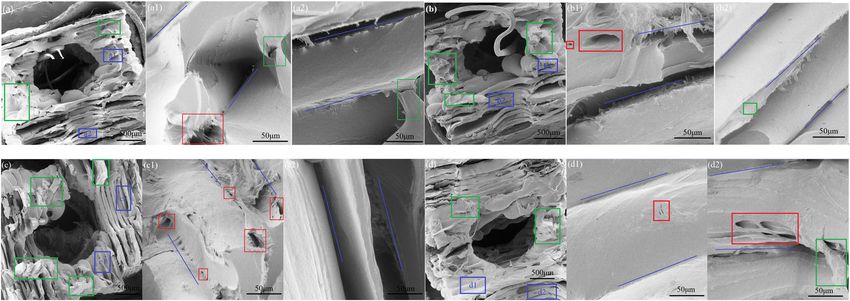
2 Xiaohui Song et al.
induced by thermal oxidation and had no way to be mechanical properties of PEEK scaffolds with uniform
improved [13]. Even though those powders could be pores using the Taguchi methodology; evaluating the rela-
reused, it will compromise on mechanical properties tionship between the different gradient pores and the
[14]. Because of the limitations of SLS of PEEK, mechanical properties with the optimal processing para-
researchers shifted their focus onto FDM of PEEK. meters; and characterizing the morphology and the tensile
In 2013, Valentan et al. [15] first used a custom-made fracture surface of PEEK scaffolds with gradient pores.
FDM machine to process PEEK. However, the products
obtained had defects including warpage, delamination,
and bubbles. After that, Vaezi and Yang [16] 3D printed
PEEK structures successfully using an extrusion AM 2 Materials and experiments
setup. However, there was a reduction in mechanical
strength because of the air gaps between the infill lines The PEEK filament was a medical-grade polymer, pur-
and inside the filaments. Therefore, to improve the quality chased from Jilin Zhongyan, China. Its properties pro-
of FDM on the manufacturing of PEEK parts, some studies vided by the manufacturer are presented in Table 1. The
have been carried out to investigate the relationship filament was applied on a high temperature FDM setup
between processing parameters and the mechanical pro- (CreatBot F430, Henan, China). The nozzle temperature
perties. Rahman et al. [17], Wu et al. [18], and Arif et al. of this FDM machine was recommended between 390 and
[19] investigated the effect of raster orientation on 430°C, and the platform can reach and keep a stable
mechanical properties of FDM PEEK and concluded that temperature at 100°C. The nozzle diameter was chosen
samples at 0° orientation showed stronger tensile proper- as 0.3 mm. With the filament and FDM machine, speci-
ties. Zalaznik et al. [20], Yang et al. [21], and Wang et al. mens prepared for tensile and compressive testing were
[22] focused on the effect of FDM processing temperature manufactured.
on the mechanical properties and the cystallinity of PEEK. For each series of Taguchi experiment, three com-
Xiaoyong et al. [23] adjusted the printing temperature and pression scaffolds were manufactured using FDM
filling ratio to improve the mechanical properties of FDM machine. As shown in Figure 1a, the scaffold was a
PEEK. Zhao et al. [24] improved the mechanical strength of porous cylinder with a dimension of 10 × 10 mm. The
PEEK through controlling the nozzle temperature, platform pores were interconnected with a diameter of 0.8 mm.
temperature, and filament diameter of FDM. Ding et al. [25] For further experiment, three dumbbell scaffolds with a
analyzed the effect of the nozzle temperature and raster dimension of 63.5 × 9.53 × 3.2 mm and four cylinder com-
orientation on the mechanical properties of FDM PEEK. pression scaffolds with a diameter of 10 mm and height of
Basgul et al. [26] and Geng et al. [27] gave the effect of 15 mm were prepared. As shown in Figure 1b, four kinds
printing speed on the PEEK parts manufactured by FDM. of interconnected gradient pores (a and b: 0.4–0.8 mm,
Deng et al. [28] comprehensively investigated the relation- 0.6–1.0 mm, 0.8–1.2 mm, and 1.2–2.0 mm) were set in
ship between the printing speed, layer thickness, and those scaffolds and increased from outer side to center.
printing temperature on the tensile properties of PEEK. Considering that the material PEEK is hard to adhere
Except those studies, the combination of computer-aided onto the platform of the FDM machine, three kinds of
methods and processing parameters were adopted to platform modifications were tried, as shown in Figure 2.
improve the quality of FDM PEEK, including finite element Figure 2a shows the platform provided by the manufac-
analysis [29] and fuzzy proportion-integration-differention turer, which was made from carbon fiber/pyroceram
(PID) method [30]. composite. The test results showed that PEEK parts
All these studies have made a significant contribu-
tion to the effects of FDM processing parameters on the
properties of PEEK. However, the PEEK parts in these Table 1: Some properties of molded PEEK
studies are not the porous structure, which is the key
for the cell attachment, proliferation, migration, and dif- Properties PEEK
ferentiation [31]. Therefore, the effect of the FDM proces- Density (g/cm3) 1.3
sing parameter on the porosity of scaffold should be Glass-transition temperature (°C) 143
evaluated for getting an optimal application in tissue Melting temperature (°C) 343
engineering. This study was about to carry out the pro- Tensile strength (MPa) 100
Flexural strength (MPa) 170
cessing of PEEK scaffold. The purposes were as follows:
Compressive strength (MPa) 125
investigating the effect of FDM parameters on the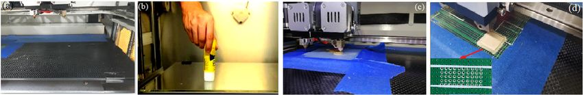
Fused deposition modeling of poly(ether ether ketone) scaffolds 3
Figure 1: The porous scaffolds with (a) uniform pores, (b) gradient pores, and (c) section of (a).
Figure 2: The modification of FDM platform: (a) a platform proved by manufacturer, (b) spreading a glue evenly on the platform, (c) pasting a
polycarbonate (PC) plate on the platform, and (d) pasting a PCB plate on the platform.
moved strongly during the FDM processing, indicating compressive properties were selected as the outputs.
that PEEK hardly adhered onto this material. Therefore, Nine series of experiments were carried out according
the following three methods were adopted: spreading a to the array. Based on the average analysis (ANOVA)
glue evenly on the platform (Figure 2b), pasting a poly- [32], the experimental results were treated.
carbonate (PC) plate on the platform (Figure 2c), and Range analysis was carried out with the porosity and
pasting a printed circuit board (PCB) on the platform compressive strength for obtaining the optimized proces-
(Figure 2d). The backside holes on PCB were drilled to sing parameters. Kij represents the average of the experi-
stepped ones. These test results showed that the glue was mental results, and Rij denotes the range and can be
able to stay the PEEK parts during the processing. How- calculated by equation (1):
ever, the spreading evenness of the glue was difficult to Rij = max(Kij) − min(Kij) i, j = 1, 2, 3, (1)
control, resulting in a certain slightly moving of the PEEK
parts during the processing. The PCB perfectly retained where i is the level and j is the sequence of the three
the PEEK parts on it. However, when removing the PEEK factors.
from the PCB, deformation of PCB and breaks on stepped The porosity of the scaffold can be obtained by equa-
holes occurred. Finally, the PC plate withstood the test by tion (2):
sticking the PEEK parts onto it and being used repeat- ρ0
edly, which was chosen to further develop the FDM Porosity = 1 − , (2)
ρPEEK
of PEEK.
The Taguchi methodology was used to determine the
relationship between FDM processing parameters and the Table 2: Arrangement of the levels to the factors
properties of scaffolds with uniform pores. The nozzle
temperature (T), the printing speed (V), and the layer Level (i) Nozzle Printing Layer thickness
temperature speed (H, mm)
thickness (H) were chosen as the studied factors, which
(T, °C) (V, mm/s)
were assigned to three levels, respectively, as presented
in Table 2. The array L9 (33) was selected, as presented in 1 390 10 0.8
2 410 20 1.0
Table 3. The three columns were assigned to T, V, and
3 430 30 1.2
H in sequence. The porosity of the scaffolds and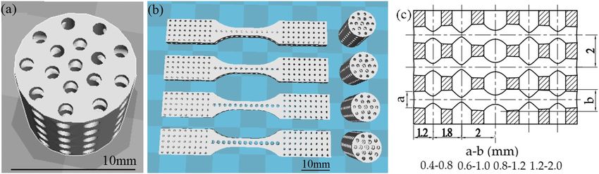
4 Xiaohui Song et al.
where ρPEEK is the theoretical densities (g/cm3) of PEEK 3 Results and discussions
filament and equals to 1.3 g/cm3 provided by the supplier;
ρ0 is the apparent density calculated through the equation
3.1 Taguchi experiment of scaffolds with
ρ0 = m0 / V0, (3) uniform pores
where m0 is the scaffold mass (g) obtained using a scale
with accuracy of 0.001 g, and V0 is the volume (mm3) of Table 3 presents the results of the Taguchi experiment.
sample measured by a Vernier caliper. The porosity of the scaffolds varies from 47 to 59% and
The compressive properties of the scaffolds were the compressive strength was in the range of 274–421 MPa,
tested using a universal testing machine (Model 8800, showing that the parameters had an important effect on the
Instron, Canton, MA). The crosshead speed and the pre- porosity and mechanical properties of the scaffolds. The
load were set as 0.5 mm/min and 0.1 N, respectively.
range analysis of the results is presented in Table 4 to further
Another universal testing machine (WDW, 20KN, Jinan
determine the optimized processing parameters. For com-
Zhongbiao, China) was used to carry out the tensile proper-
pressive strength, the optimum combination was T3V1H3,
ties with a preload of 0.1 N and a testing rate of 0.05 mm/s.
which was contributing to the nozzle temperature of 430°C,
The average values of the testing strength and strain for each
the printing speed of 10 mm/s, and the layer thickness of
sample were obtained through four measurements.
0.08 mm. On the contrary, the optimal assembly for porosity
The morphology of the manufacturing surface and
was T1V3H2, which was corresponding to the nozzle tem-
the fractural surface was observed. The test was carried
perature of 390°C, the printing speed of 30 mm/s, and the
out using a scanning electron microscopy (SEM, VEGA3
layer thickness of 0.12 mm. For a scaffold applied in tissue
TESCAN). Before testing, all the scaffolds were gold
engineering, larger strength means stronger anti-bearing
coated for 3 min.
Table 3: The results of Taguchi experiment
Temperature (°C) Printing speed (mm/s) Layer thickness (mm) Porosity (%) Compressive strength (MPa)
390 10 0.12 49.72 ± 0.77 325.25 ± 2.19
390 20 0.08 51.28 ± 0.7 336.85 ± 1.83
390 30 0.1 58.67 ± 0.39 274.59 ± 6.56
410 10 0.08 48.81 ± 0.1 381.89 ± 0.94
410 20 0.1 49.71 ± 0.37 353.92 ± 0.22
410 30 0.12 54.42 ± 0.76 363.24 ± 0.39
430 10 0.1 47.72 ± 0.01 421.48 ± 5.72
430 20 0.12 51.92 ± 0.28 367.02 ± 5.57
430 30 0.08 47.27 ± 0.92 402.45 ± 6.28
Table 4: The range analysis of the compressive strength and porosity
Range Compressive strength (MPa) Porosity (%)
T V H T V H
K1j 312.23 376.21 373.73 53.22 48.75 49.12
K2j 366.35 352.60 350.00 50.98 50.97 52.03
K3j 396.98 346.76 351.84 48.97 53.45 52.02
R 84.75 29.45 23.73 4.25 4.7 2.91
Optimum levels T3 V1 H3 T1 V3 H2
Optimum assembly T3V1H3 T1V3H2
Order of priority TVH VTH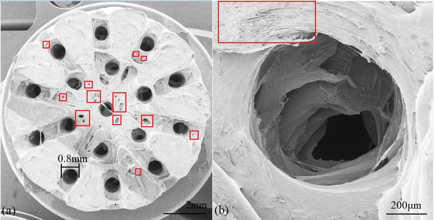
Fused deposition modeling of poly(ether ether ketone) scaffolds 5
capacity [33], and higher porosity is benefit to the bone The effect of layer thickness on the compressive
ingrowth [34]. Therefore, here a compromise was needed. strength and the porosity was the weakest among the
From Table 4, it can be seen that higher temperature three factors. Although there was almost no difference
was benefit to the strength and was able to decrease the at the layer thickness 0.1 and 0.12 mm for the average
porosity. This result was similar to that in other litera- compressive strength and porosity (350 MPa and 52%),
tures [21,25,30]. Higher temperature provided more heat the gap was still big between 0.08 and 0.1 mm (373.73 MPa
to make PEEK to melt well and gave the molecular chains and 49.12%). When manufacturing with smaller layer thick-
more energy to rearrange. The micro-voids inside the part ness, the redundant heat released from the printing layer
can be decreased in higher temperature, resulting in a can be absorbed by the former layer, resulting in a stronger
higher strength and density. Meanwhile, higher tempera- bond between two layers. However, when the layer thick-
ture provided longer time for PEEK to crystallize because ness was very small, there was no enough room for the
of a larger difference with the ambient temperature. Lite- redundant melting polymers, which will be aggressive
rature [21] reported that the increase in crystallinity under the situation of higher nozzle temperature and lower
improved the yield strength of PEEK but decreased its printing speed. Therefore, those superfluous melts flowed to
toughness. Therefore, the compressive strength of PEEK other room, resulting in the congested pores in the scaffold,
in this study should be enhanced in higher nozzle tem- as shown in Figure 3d. The blocking pores would not be able
perature. It can also be proved by the picture of the FDM to provide ways for bone cells to ingrowth.
scaffolds in Figure 3. Scaffold in Figure 3b showed In a conclusion, although higher temperature and
brighter surface than scaffold in Figure 3a. Polymer parts lower speed were benefit to the crystalline of PEEK,
with brighter surface had higher crystallinity than those they prevented the forming of micro pores. Micro pores
with darker surface. Therefore, the scaffold in Figure 3b were the key for bone cells to ingrowth and migrate.
possessed higher strength (367.02 MPa) than scaffold in Therefore, a moderate temperature and printing speed
Figure 3a (336.85 MPa). should be chosen. The layer thickness had the weakest
Increasing the printing speed had a negative effect effect on the strength and the porosity, so a modest
on the compressive strength and density of PEEK. The choice for it should be fine. As a result, the optimum
effect of printing speed on the strength of PEEK was processing parameters were determined as: the nozzle
similar to that in the literature [30]. When PEEK melts temperature of 410°C, the printing speed of 20 mm/s,
were squeezed quickly, the molecular of PEEK had insuf- and the layer thickness of 0.1 mm. With the optimum
ficient time to unfold and orient, weakening the bonding processing parameters, the compression and tensile
strength between two adjacent printing lines and layers. sample were manufactured and tested. The sample was
At the same time, the PEEK filaments absorbed less energy designed as porous scaffold with uniform pores of
when being squeezed from nozzle at the higher speed, 0.8 mm in diameter, as shown in Figure 4. Figure 4a
lowering the crystallinity of PEEK. Therefore, the scaffold showed that most of the pores in scaffold were exact
in Figure 3c, which was manufactured with higher printing 0.8 mm in diameter, indicating that the dimension of
speed (30 mm/s) and lower nozzle temperature (390℃), scaffold can be controlled during the FDM processing.
possessed dark and rough surface [35]. The result indi- Some pores were a little less than 0.8 mm, which might
cated that the printing speed of 30 mm/s might too fast because of the molecular swell of PEEK melts (Figure 4b).
for ensuring the quality of the PEEK scaffold.
Figure 3: The PEEK scaffold in different processing condition (the
nozzle temperature, the printing speed, and the layer thickness): (a)
390°C, 20 mm/s, 0.08 mm; (b) 430°C, 20 mm/s, 0.12 mm; (c) Figure 4: The surface morphology of (a) a scaffold with uniform
390°C, 30 mm/s, 0.1 mm; and (d) 430°C, 10 mm/s, 0.1 mm. pores and (b) the enlarger of the one of the pores.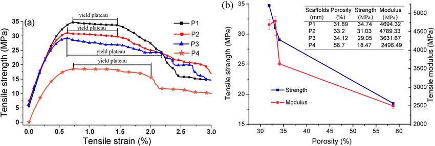
6 Xiaohui Song et al.
There were many micro-pores (5–40 μm) on the surface of failure. When the cracks stopped to propagate and dis-
scaffold (red rectangle), contributing to the air gap appeared because of the compression, the procedure
during the process. Literatures [36,37] showed that pores went to the second yield phase (picture 6). In this stage,
in size of 10–75 μm allowed the fibrous tissue to penetrate all the pores were compressed until disappeared. Finally,
into. Therefore, the PEEK scaffold with micro pores in size the compression went to the densification stage, where
of 5–40 μm was benefit to the penetration of fibrous the scaffold was densified (picture 7). The failure of this
tissue. scaffold probably because of the speed was very fast and
the layer thickness was very large, resulting in partial
weakness of the scaffold.
3.2 Analysis of the compression procedure
of FDM PEEK scaffold
3.3 FDM of PEEK scaffolds with gradient
Section 3.1 proved the importance of the FDM processing pores
parameters, which not only affected the morphology,
porosity, and mechanical properties, but also decided 3.3.1 Surface macro morphology of PEEK scaffolds
the success use of a scaffold. Figure 5 shows a failed
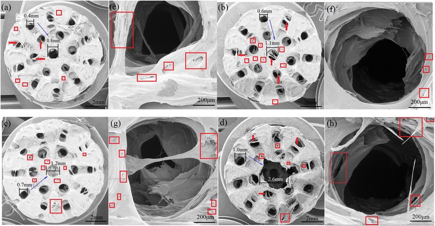
example of compression of PEEK scaffold. The compres- With the determined processing parameters, PEEK scaf-
sion procedure of this example scaffold included five folds with gradient pores were manufactured using FDM.
stages as follows: elastic, yield, partial failure, yield, The diameter of the pores was gradually increasing from
and densification. During the first stage, the scaffold outer side to the center of the scaffold (blue arrow) as
(picture 1), along with its pores, decreased in height follows: 0.4–0.8 mm, 0.6–1.1 mm, 0.7–1.2 mm, and
and increased in parallel direction under the downward 1.0–2.6 mm, as shown in Figure 6. Han et al. [38] proved
load. In this period, the pores deformed without collapse that a scaffold with pores in size of 483–905 μm provided
and can be recovered to its original shape. After that, the more space for tissue ingrowth. In this study, the pore
scaffold came into the first yield phase because of a weak size was larger than 400 μm, which was able to provide
point (red arrow), which resulted in a collapse (picture 2). more room for the tissue and cells ingrowth, migration,
This weak point caused the scaffold to distort, resulting and proliferation. Some melts were extruded across the
in a compressive deformation on the right side and a ten- pores (red arrow), leading to some partial shelter (Figure
sile deformation on the left side of the scaffold (picture 3). 6a, b, and d) and a whole block (Figure 6c). Fortunately,
When the beams around the tensile area were broken (red there were some micro pores (10–60 μm) on the shelters
rectangle), the second stage was finished (picture 4). At (red rectangle, Figure 6e–h), providing ways for tissues to
this stage, the strength increased slowly from 30 to penetrate. In addition, micro-pores were showed on the
38.39 MPa. Then the crack further propagated to lower surface of scaffolds (red rectangle) and the wall of pores.
the strength (picture 5), and this stage was called partial As analyzed previously, fibrous tissue was able to pene-
trate into micro-pores in size of 10–75 μm [36,37]. The
dimension of pores in Figure 6a was controlled well,
resulting in similar average diameter to that of the
designed pores. On the contrary, the pore in the center
of the scaffold was larger than the design, probably
because the pore was designed very large.
All the pores were interconnected with each other,
bonded by scaffold beams, and uniformly transited from
outer side to the center of scaffolds. This kind of pore
transition was in accordance with that of human bones
from cortical bone to trabecular bone, indicating that the
osteoblasts and mesenchymal cells can attach, migrate,
and proliferate quickly. The larger interconnected pores
were benefit to the bone ingrowth and osseointegration
Figure 5: Example of a failed compression of PEEK scaffolds. of implants after surgery [39]. The surface of pores was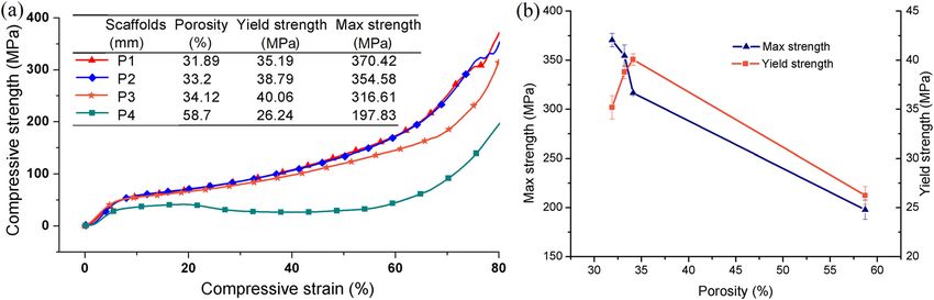
Fused deposition modeling of poly(ether ether ketone) scaffolds 7
Figure 6: The surface morphology of PEEK scaffolds with pores gradual between: (a) 0.4–0.8 mm, (b) 0.6–1.0 mm, (c) 0.8–1.2 mm and
(d) 1.2–2.0 mm; (e–h) are the enlargers of the blue rectangles in (a–d), respectively.
rough (Figure 6e–h) due to the swell of PEEK melts. scaffolds. It can be seen from Figure 7b, with the increase
Rough surface was significantly important for the in the pore size, the porosity of the scaffolds increased
osseointegration of implants [40], and could enhance from 31.89 to 58.7%, but the strength and modulus
the attachment, migration, and differentiation of cells decreased from 34.74 and 4694.32 MPa to 18.47 and
for bone forming [41]. 2496.49 MPa, respectively. The low strength and modulus
of sample P4 were probably because of its larger gradient
pores. During the tensile procedure, the samples showed
3.3.2 Mechanical properties of the PEEK scaffolds obvious yield plateau (Figure 7a). Although the tensile
strength and modulus decreased with the increase in
Figure 7 shows the tensile curves of the scaffolds and the the porosity, the yield plateau became longer. The longer
effect of porosity on the tensile strength and modulus of plateau of scaffolds P3 and P4 was probably because
Figure 7: The relationship between: (a) strength and strain and (b) porosity and strength, modulus (P1, P2, P3, and P4 represent the
scaffolds with pores gradual between 0.4 and 0.8 mm, 0.6 and 1.0 mm, 0.8 and 1.2 mm, and 1.2 and 2.0 mm, respectively).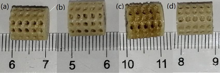
8 Xiaohui Song et al.
Figure 8: The relationship between: (a) strength and strain and (b) porosity and strength, modulus (P1, P2, P3, and P4 represent the
scaffolds with pores gradual between 0.4 and 0.8 mm, 0.6 and 1.0 mm, 0.8 and 1.2 mm, and 1.2 and 2.0 mm, respectively).
of the overlapping interlayer around the central pore The tensile strength and compressive strength of
(Figure 6c and d). The result indicated that the anti- human’s cordial bone were provided as 50–150 MPa
deforming capacity of scaffolds with larger pores and and 106–215 MPa by Wang et al. [42] and Lawson and
porosity was enhanced. Czernuszka [43]. Morgan and Keaveny [44] concluded
Figure 8 shows the compression curves of the scaf- the mechanical properties of trabecular bone: the tensile
folds and the effect of porosity on the compressive strengths for the vertebra, proximal tibia, and greater
strength of scaffolds. With the increase in pore size trochanter were 1.72, 4.5, and 2.44 MPa, respectively;
from 0.4–0.8 mm to 1.2–2.0 mm, the porosity increased the compressive yield strengths for vertebra, proximal
from 31.89 to 58.7%, but the maximum strength tibia, and greater trochanter were 2.02, 5.83, and
decreased from 370.42 to 197.83 MPa (Figure 8b). The 3.21 MPa, respectively. In this study, the compressive
yield strength rose up moderately first and reached the yield strength was between 26 and 36 MPa, and the ten-
peak at scaffold P3 (40.06 MPa), followed by a dramatic sile strength was in the range of 18–35 MPa. Both the
drop to the bottom (26.24 MPa). It should be noticed that compressive and tensile strengths of scaffolds were
although P4 had the lowest strength, its yield plateau between the trabecular bones and the cordial bones.
was the longest, showing the highest anti-deforming Meanwhile, the scaffolds were designed to integrate the
capacity among the four kinds of scaffolds (Figure 8a). cordial and trabecular bones into one piece. Therefore,
Figure 9: The tensile fractural morphology of PEEK scaffolds with pores gradual between: (a) 0.4 and 0.8 mm, (b) 0.6 and 1.0 mm, (c) 0.8 and
1.2 mm, and (d) 1.2 and 2.0 mm; (a1) and (a2), (b1) and (b2), (c1) and (c2), and (d1) and (d2) are the enlargers of the blue rectangles in (a–d),
respectively.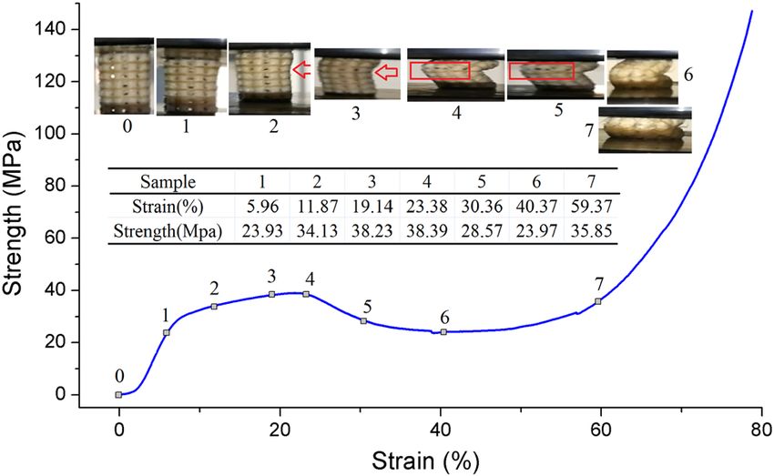
Fused deposition modeling of poly(ether ether ketone) scaffolds 9
the scaffolds manufactured using FDM can satisfy the FDM. Those pores were interconnected and gradually
loading requirements of human bones. increased from outer side to the center of the scaffolds.
The interconnected pores and the rough surface of
the pores can allow the attachment, migration, and differ-
3.3.3 Tensile fractural morphology of PEEK scaffolds entiation of cells for bone forming. The results of experi-
ment revealed that the porosity of scaffolds was in the
Figure 9 shows the tensile fractural morphology of the range of 31–59%, and the tensile strength, compressive
PEEK scaffolds manufactured using FDM. All the scaf- max strength, and compressive yield strength are between
folds fractured through the cross of pores were the 18–35 MPa, 197.83–370.42 MPa, and 26–36 MPa, respec-
weakest part of the scaffold. Four kinds of fractural sur- tively. The mechanical properties of the scaffolds can
faces were unsmooth, showing various degrees of over- satisfy the loading requirements of human bones.
lapping structure between layers, which indicated that Therefore, the PEEK scaffolds have a potential to be used
the interlayer bonding was strong. The overlapping in tissue engineering as implants.
(green rectangle) was at the two sides of the center pore in
Figure 9a and b, and was around the center pore in Figure 9c Acknowledgments: The authors gratefully acknowledge
and d. This phenomenon showed that the scaffolds with financial support from the institution of National Nature
higher porosity and larger pores possessed stronger inter- Science Foundations of China (51705094 and 51965014)
layer force that needed more energy to break the part. and the institution of Guangxi Nature Science Founda-
There were some gaps between layers (blue line) in frac- tions (2018JJA160268 and 2018JJA160218).
ture surfaces of Figure 9a2, b1, and c2, which showed that
the combination between layers was not well during the Research funding: This study was funded by National
FDM processing. The interlayer gaps expanded further Nature Science Foundations of China (51705094 and
and developed to macroscopic fracture under the loading 51965014) and Nature Science Foundations of Guangxi
of tensile, leading to the failure of the scaffolds. A craze (2018JJA160268 and 2018JJA160218).
shown in Figure 9d1 generated in the fractural surface of
scaffold with 1.2–2.0 mm of gradient pores. Literature Author contributions: Xiaohui Song: writing, revision,
showed that the craze can consume lots of energy for and funding. Dengwen Shi: experiment and data.
propagation, which in turn restricts the growth of craze Pinghui Song: medical information and data. Xingguo
itself [25]. Therefore, the craze was benefit to improving Han: funding. Qingsong Wei: revision. Chuanmo
the toughness of PEEK scaffolds. Meanwhile, some micro- Huang: graphics.
pores (red rectangle) were found in Figure 9a1, b1, c1, and
d2 along the printing lines (blue line), where air was Conflict of interest: There is no interests conflict with
grasped during the FDM process. Those air pores will pre- others.
vent the force transfer and resulted in the failure of the
scaffold. Data availability statement: All authors can confirm that
all data used in this article can be published the Journal
“High Temperature Materials and Processes”.
4 Conclusion
This paper studied the effect of processing parameters of
References
FDM on the porosity and compressive strength of PEEK
scaffold with uniform pores (0.8 mm of diameter). The
[1] Roskies, M., J. O. Jordan, D. Fang, M. N. Abdallah, M. P. Hier,
platform was modified by pasting a PC plate on it. The A. Mlynarek, et al. Improving PEEK bioactivity for craniofacial
parameters were determined as follows: the nozzle tem- reconstruction using a 3D printed scaffold embedded with
perature of 410°C, the printing speed of 20 mm/s, and the mesenchymal stem cells. Journal of Biomaterials Applications,
layer thickness of 0.1 mm, by comprehensively consid- Vol. 31, No. 1, 2016, pp. 132–139.
[2] Wong, K. L., C. T. Wong, W. C. Liu, H. B. Pan, M. K. Fong, W. M.
ering the porosity and the strength of PEEK scaffolds.
Lam, et al. Mechanical properties and in vitro response of
With the determined parameters, four kinds of PEEK strontium-containing hydroxyapatite/polyetheretherketone
scaffolds with gradient pores (0.4–0.8 mm, 0.6–1.0 mm, composites. Biomaterials, Vol. 30, No. 23–24, 2009,
0.8–1.2 mm, and 1.2–2.0 mm) were manufactured using pp. 3810–3817.10 Xiaohui Song et al.
[3] Geetha, M., A. K. Singh, R. Asokamani, and A. K. Gogia. [18] Wu, W., P. Geng, G. Li, D. Zhao, H. Zhang, and J. Zhao. Influence
Ti based biomaterials, the ultimate choice for orthopaedic of layer thickness and raster angle on the mechanical properties
implants – a review. Progress in Materials Science, Vol. 54, of 3D-printed PEEK and a comparative mechanical study
No. 3, 2009, pp. 397–425. between PEEK and ABS. Materials, Vol. 8, No. 9, 2015,
[4] Han, X., N. Sharma, Z. Xu, L. Scheideler, J. Geis-Gerstorfer, pp. 5834–5846.
F. Rupp, et al. An in vitro study of osteoblast response on [19] Arif, M. F., S. Kumar, K. M. Varadarajan, and W. J. Cantwell.
fused-filament fabrication 3D printed PEEK for dental and Performance of biocompatible PEEK processed by fused
cranio-maxillofacial implants. Journal of Clinical Medicine, deposition additive manufacturing. Materials and Design,
Vol. 8, No. 6, 2019, p. 771. Vol. 146, 2018, pp. 249–259.
[5] Ma, R., and T. Tang. Current strategies to improve the bio- [20] Zalaznik, M., M. Kalin, and S. Novak. Influence of the proces-
activity of PEEK. International Journal of Molecular Sciences, sing temperature on the tribological and mechanical proper-
Vol. 15, No. 4, 2014, pp. 5426–5445. ties of poly-ether-ether-ketone (PEEK) polymer. Tribology
[6] Godara, A., D. Raabe, and S. Green. The influence of sterili- International, Vol. 94, 2016, pp. 92–97.
zation processes on the micromechanical properties of carbon [21] Yang, C., X. Tian, D. Li, Y. Cao, F. Zhao, and C. Shi. Influence
fiber-reinforced PEEK composites for bone implant of thermal processing conditions in 3D printing on the
applications. Acta Biomaterialia, Vol. 3, No. 2, 2007, crystallinity and mechanical properties of PEEK material.
pp. 209–220. Journal of Materials Processing Technology, Vol. 248,
[7] Clyne, A. M. Thermal processing of tissue engineering scaf- 2017, pp. 1–7.
folds. Journal of Heat Transfer, Vol. 133, No. 3, 2011, [22] Wang, R., K. Cheng, R. C. Advincula, and Q. Chen. On the
p. 034001. thermal processing and mechanical properties of 3D-printed
[8] Singh, S., C. Prakash, and S. Ramakrishna. 3D printing of polyether ether ketone. MRS Communications, Vol. 9, No. 3,
polyether-ether-ketone for biomedical applications. European 2019, pp. 1046–1052.
Polymer Journal, Vol. 114, 2019, pp. 234–248. [23] Xiaoyong, S., C. Liangcheng, M. Honglin, G. Peng, B. Zhanwei,
[9] Schmidt, M., D. Pohle, and T. Rechtenwald. Selective laser and L. Cheng. Experimental analysis of high temperature PEEK
sintering of PEEK. CIRP Annals, Vol. 56, No. 1, 2007, materials on 3D printing test. 9th international conference on
pp. 205–208. measuring technology and mechatronics automation, 14–15
[10] Tan, L. J., W. Zhu, and K. Zhou. Recent progress on polymer Jan 2017. IEEE, Changsha, China, 2017.
materials for additive manufacturing. Advanced Functional [24] Zhao, F., D. Li, and Z. Jin. Preliminary investigation of poly-
Materials, Vol. 30, No. 43, 2020, p. 2003062. ether-ether-ketone based on fused deposition modeling for
[11] Raja, B. K., R. J. P. Raja, K. Karan, R. Soundararajan, and medical applications. Materials, Vol. 11, No. 2, 2018, p. 288.
P. Ashokavarthanan. Parameter optimization for polyamide in [25] Ding, S., B. Zou, P. Wang, and H. Ding. Effects of nozzle tem-
selective laser sintering based on mechanical behavior. 3D perature and building orientation on mechanical properties
printing and additive manufacturing technologies//Parameter and microstructure of PEEK and PEI printed by 3D-FDM.
optimization for polyamide in selective laser sintering based Polymer Testing, Vol. 78, 2019, p. 105948.
on mechanical behavior. Springer, Singapore, 2019. [26] Basgul, C., T. Yu, D. W. MacDonald, R. Siskey, M. Marcolongo,
[12] Gusarov, A. V., T. Laoui, L. Froyen, and V. I. Titov. Contact and S. M. Kurtz. Structure-property relationships for 3D
thermal conductivity of a powder bed in in selective laser printed peek intervertebral lumbar cages produced using
sintering. International Journal of Heat and Mass Transfer, fused filament fabrication. Journal of Materials Research,
Vol. 46, 2003, pp. 1103–1109. Vol. 33, No. 14, 2018, pp. 2040–2051.
[13] Yuan, S., F. Shen, C. K. Chua, and K. Zhou. Polymeric compo- [27] Geng, P., J. Zhao, W. Wu, W. Ye, Y. Wang, S. Wang, et al. Effects
sites for powder-based additive manufacturing: Materials and of extrusion speed and printing speed on the 3D printing
applications. Progress in Polymer Science, Vol. 91, 2019, stability of extruded PEEK filament. Journal of Manufacturing
pp. 141–168. Processes, Vol. 37, 2019, pp. 266–273.
[14] Ghita, O. R., E. James, R. Trimble, and K. E. Evans. Physico- [28] Deng, X., Z. Zeng, B. Peng, S. Yan, and W. Ke. Mechanical
chemical behaviour of poly (ether ketone) (PEK) in high properties optimization of poly-ether-ether-ketone via fused
temperature laser sintering (HT-LS). Journal of Materials deposition modeling. Materials, Vol. 11, No. 2, 2018, p. 216.
Processing Technology, Vol. 214, No. 4, 2014, [29] Liu, Z., G. Wang, Y. Huo, and W. Zhao. Research on precise
pp. 969–978. control of 3D print nozzle temperature in PEEK material. 2nd
[15] Valentan, B., Ž. Kadivnik, T. Brajlih, A. Anderson, and international conference on materials science, resource and
I. Drstvenšek. Processing poly(ether etherketone) an a 3D environmental engineering, October 2017. AIP Publishing,
printer for thermoplastic modelling. Materials and Hubei, China, 2018.
Technology, Vol. 47, No. 6, 2013, pp. 715–721. [30] Wang, P., B. Zou, H. Xiao, S. Ding, and C. Huang. Effects of
[16] Vaezi, M., and S. Yang. Extrusion-based additive manufac- printing parameters of fused deposition modeling on
turing of PEEK for biomedical applications. Virtual and mechanical properties, surface quality, and microstructure of
Physical Prototyping, Vol. 10, No. 3, 2015, pp. 123–135. PEEK. Journal of Materials Processing Technology, Vol. 271,
[17] Rahman, K. M., T. Letcher, and R. Reese. Mechanical proper- 2019, pp. 62–74.
ties of additively manufactured PEEK components using fused [31] Watson, N. J., R. K. Johal, Z. Glover, Y. Reinwald, L. J. White,
filament fabrication. Proceedings of the ASME 2015 inter- A. M. Ghaemmaghami, et al. Post-processing of polymer foam
national mechanical engineering congress and exposition. tissue scaffolds with high power ultrasound: a route to
Houston, Texas, 2015. increased pore interconnectivity, pore size and fluid transport.Fused deposition modeling of poly(ether ether ketone) scaffolds 11
Materials Science and Engineering C, Vol. 33, No. 8, 2013, [38] Han, C., Y. Li, Q. Wang, S. Wen, Q. Wei, C. Yan, et al.
pp. 4825–4832. Continuous functionally graded porous titanium scaffolds
[32] Taguchi, G, and R. Jugulum. The Mahalanobis-Taguchi manufactured by selective laser melting for bone implants.
strategy: a pattern technology system. John Wiley & Sons, Journal of the Mechanical Behavior of Biomedical Materials,
New York, 2002. Vol. 80, 2018, pp. 119–127.
[33] Hacking, S. A., J. D. Bobyn, K. Toh, M. Tanzer, and J. J. Krygier. [39] Xiaohui, S., L. Wei, S. Pinghui, S. Qingyong, W. Qingsong,
Fibrous tissue ingrowth and attachment to porous tantalum. S. Yusheng, et al. Selective laser sintering of aliphatic-poly-
Journal of Biomedical Materials Research, Vol. 52, No. 4, 2000, carbonate/hydroxyapatite composite scaffolds for medical
pp. 631–638. applications. The International Journal of Advanced
[34] Wang, J., Y. Asou, I. Sekiya, S. Sotome, H. Orii, and Manufacturing Technology, Vol. 81, No. 1–4, 2015, pp. 15–25.
K. Shinomiya. Enhancement of tissue engineered bone [40] Lima, D. D., S. Lemperle, P. C. Chen, R. E. Holmes, and C. W.
formation by a low pressure system improving cell seeding Colwell. Bone response to implant surface morphology. The
and medium perfusion into a porous scaffold. Biomaterials, Journal of Arthroplasty, Vol. 13, No. 8, 1998, pp. 928–934.
Vol. 27, No. 13, 2006, pp. 2738–2746. [41] Yuan, H., K. Kurashina, J. D. de Bruijn, Y. Li, K. de Groot, and
[35] Kurtz, S. M., J. Day, and K. Ong. Isoelastic polyarylether- X. Zhang. A preliminary study on osteoinduction of two kinds
etherketone implants for total joint replacement//PEEK of calcium phosphate ceramics. Biomaterials, Vol. 20, No. 19,
biomaterials handbook. William Andrew Publishing, 1999, pp. 1799–1806.
New York, 2012. [42] Wang, M., D. Porter, and W. Bonfield. Processing, character-
[36] Morelli, S., D. Facciolo, A. Messina, A. Piscioneri, S. Salerno, isation, and evaluation of hydroxyapatite reinforced poly-
E. Drioli, et al. Polycaprolactone-hydroxyapatite composite ethylene. British Ceramics Transactions, Vol. 93, 1994,
membrane scaffolds for bone tissue engineering. Materials pp. 91–95.
Research Society Symposium Proceedings, Vol. 1502, 2013, [43] Lawson, A. C., and J. Czernuszka. Collagen-calcium phosphate
pp. mrsf12-1502-t01-09. composites. Proceedings of the Institution of Mechanical
[37] Shoufeng, Y., K. F. Leong, Z. Du, and C. K. Chua. Review: Engineers: Part H, Vol. 212, 1998, pp. 413–425.
the design of scaffolds for use in tissue engineering. Part I. [44] Morgan, E. F., and T. M. Keaveny. Dependence of yield strain of
Traditional factors. Tissue Engineering, Vol. 7, No. 6, 2001, human trabecular bone on anatomic site. Journal of
pp. 680–689. Biomechanics, Vol. 34, No. 5, 2001, pp. 569–577.You can also read