H2020-ICT-732410 ROBMOSYS COMPOSABLE MODELS AND SOFTWARE FOR ROBOTICS SYSTEMS
←
→
Page content transcription
If your browser does not render page correctly, please read the page content below
Ref. Ares(2017)3348363 - 04/07/2017

            H2020-ICT-732410

                      RobMoSys
Composable Models and Software
    for Robotics Systems

             Deliverable D3.1:
First motion, perception and world-model
           stacks specifications

     This project has received funding from the European Union’s Horizon 2020 research
     and innovation programme under grant agreement N732410.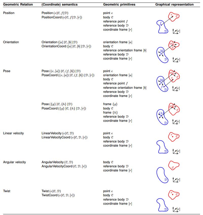
RobMoSys - D3.1                                                      H2020-ICT-732410

   Project acronym:               RobMoSys
   Project full title:            Composable Models and Software for Robotics Systems

   Work Package:                  WP 3
   Document number:               D3.1
   Document title:                First motion, perception and world-model stacks specifica-
                                  tions
   Version:                       1.1

   Delivery date:                 4 July, 2017
   Nature:                        Report (R)
   Dissemination level:           Public (PU)

   Editor:                        Enea Scioni (KUL), Herman Bruyninckx (KUL)
   Authors:                       Enea Scioni (KUL), Nico Hübel (KUL), Herman Bruyn-
                                  inckx (KUL), Alex Lotz (HSU), Dennis Stampfer (HSU),
                                  Christian Schlegen (HSU)
   Reviewer:                      Alex Lotz (HSU)
This project has received funding from the European Union’s Horizon 2020 research and innovation
programme under grant agreement No 732410 RobMoSys.

                                                 2
Executive Summary
This deliverable provides the first contribution on the modelling of the so-called motion, perception
and world model stacks, since these are foundations of any digital platform for robotic systems.
The first part of the modelling focuses on the generic foundations, that the domain of robotics
shares with a lot of other domains. More in particular, we need formal representations of (i)
entities, relations and property graphs, (ii) at the levels of abstraction of mereology, topology, ge-
ometry, and dynamics, (iii) with separation of the concerns of mechanism (structure & behaviour)
and policy, and (iv) with an explicit ambition to support grounding into software implementa-
tions, and processes of validation and certification of components and systems. Two core aspects
are: the omnipresence of the Block-Port-Connector meta meta model to represent all structural
relationships and compositions, and the introduction of a formal model to represent the data
structures, functions and control flow schedules of algorithms.
The second part of the modelling brings in robotics-specific material, more specifically about
motion and perception. Both share the same formalisation of their mathematical, numerical and
digital representations, as well as the connection to meta data for physical dimensions and units.
The motion stack core consist of models of geometrical entities, relations and constraints, from
points and lines upto kinematic chains with shape, inertia, actuators and sensors. The major
“behavioural” functionality to be modelled explicitly is that of the hybrid dynamics solvers that is
the generic basis of all instantaneous motion and force transformations between the joint space
and the Cartesian space of all kinematic chains. Similarly, perception is composed of models
of sensors, sensing features, data association to object features, and constraints imposed by the
task, the environment and the object properties; message passing is the solver which plays a
similar foundational role in adding behaviour to the models in perception as the hybrid dynamics
algorithm does for motion. The world model stack is a knowledge-based system, backbone of the
information infrastructure around the motion and perception stacks.
3Contents
1 Introduction 5
1.1 Goal of First Call . . . . . . . . . . . . . . . . . . . . . . . . . . . . . . . . . . 5
1.2 Generic modelling foundations . . . . . . . . . . . . . . . . . . . . . . . . . . . 6
1.2.1 Entities, Relations and Property graphs . . . . . . . . . . . . . . . . . . 6
1.2.2 Mereology, topology, geometry, dynamics . . . . . . . . . . . . . . . . . 9
1.2.3 Mechanism (structure & behaviour) versus policy . . . . . . . . . . . . . 10
1.2.4 Grounding, validation, certification . . . . . . . . . . . . . . . . . . . . 11
2 Motion Stack Overview 12
3 Motion Stack Models 14
3.1 Numerical Entity Model . . . . . . . . . . . . . . . . . . . . . . . . . . . . . . . 15
3.2 Digital Data Representation . . . . . . . . . . . . . . . . . . . . . . . . . . . . . 16
3.2.1 Digital Representation (meta-)Models and Examples . . . . . . . . . . . 17
3.2.2 Why digital data representation models are important? . . . . . . . . . . 21
3.3 Physical Units and Dimensions Model . . . . . . . . . . . . . . . . . . . . . . . 22
3.3.1 Role of the physical units and dimensions . . . . . . . . . . . . . . . . . 22
3.4 Coordinate Representation . . . . . . . . . . . . . . . . . . . . . . . . . . . . . 22
3.5 Coordinate Representation, digital data representation and physical Units . . . . 23
3.6 Models of Uncertainties . . . . . . . . . . . . . . . . . . . . . . . . . . . . . . . 25
3.7 Geometric Semantics of Relations between Rigid Bodies . . . . . . . . . . . . . . 26
3.7.1 Geometric Primitives . . . . . . . . . . . . . . . . . . . . . . . . . . . . 26
3.7.2 Geometric Relations . . . . . . . . . . . . . . . . . . . . . . . . . . . . . 28
3.7.3 Coordinate Representations for Geometric Semantics . . . . . . . . . . . 31
3.8 Kinematic Modeling . . . . . . . . . . . . . . . . . . . . . . . . . . . . . . . . . 33
3.8.1 Describing a kinematic model with the Block-Port-Connector meta-model 34
3.9 Composing the joint model with rigid body dynamics . . . . . . . . . . . . . . . 35
3.10 Composing joint models into a kinematic chain model . . . . . . . . . . . . . . 36
3.10.1 Hybrid dynamics solvers . . . . . . . . . . . . . . . . . . . . . . . . . . 36
3.11 Task Specification in the Motion Stack . . . . . . . . . . . . . . . . . . . . . . 39
3.11.1 The relevance of the Task Monitoring during Execution . . . . . . . . . . 41
3.11.2 Constraint-based Task Specifications . . . . . . . . . . . . . . . . . . . . 42
3.12 Models of Algorithms . . . . . . . . . . . . . . . . . . . . . . . . . . . . . . . . 42
4 Perception and World Model Stacks 46
4.1 Introduction . . . . . . . . . . . . . . . . . . . . . . . . . . . . . . . . . . . . . 46
4.2 Modelling . . . . . . . . . . . . . . . . . . . . . . . . . . . . . . . . . . . . . . 46
4.3 Example . . . . . . . . . . . . . . . . . . . . . . . . . . . . . . . . . . . . . . . 48
4.4 World Model . . . . . . . . . . . . . . . . . . . . . . . . . . . . . . . . . . . . . 50
4.4.1 World Model Specifications . . . . . . . . . . . . . . . . . . . . . . . . . 53
41. Introduction
“Motion” and “Perception” are two essential functionalities in any robotic system, and both have
a rich and mature history. In other words, there is more than enough understanding about what
constitutes a solid basis of theory and algorithms to include in a digital platform for robotics. For
the motion part, this basis is given by the generic algorithm to solve the “hybrid” instantaneous
kinematics and dynamics relationships that hold between the forces and the motions on ideal,
lumped-parameter, kinematic chains. For the perception part, a similar role is played by Bayesian
graphical model templates that relate raw sensor data to the task-centred features of objects
involved in the robots’ tasks.
This Deliverable makes concrete suggestions about how to turn those state-of-the-art insights
into a concrete set of (meta) models, on which to base any concrete implementation for any
concrete application in robotics. Because the ambition of the Robmosys project is to (help)
build the platform only, a lot of attention was given to creating the “right” modularity, the
“right” levels of detail, and the “right” separation of concerns, and the “right” approach towards
composability, such that the development of models, tools, implementations and applications
becomes methodological, transparant and scalable.
1.1 Goal of First Call
This deliverable contains the drafts of the Motion Stack and the Perception Stack as examples
for Tier 2 domain-specific models within the RobMoSys structure. These drafts will be subject
to changes and refinements over the course of the project, not in the least because achieving
the envisaged “right” set of models is probably a never ending process of community-driven
improvements. The latest versions can always be found on the RobMoSys Wiki. Constructive
feedback from the community is welcome and encouraged and can be subject of projects in the
first call.
For the first call we consider the following subjects for project proposals:
• (Meta-)Models. Creating or refining Tier 2 domain-specific models. This includes refine-
ments of the presented motion or perception stack as well as proposals for neighbouring
domains such as control, estimation, planning, visualisation, data acquisiation and manage-
ment, or decision making. This also includes work on how to encode these formal models
(e.g. with domain-independent host languages such as JSON-LS, OWL, XML, etc.), so that
they can be used in tooling prototypes. Finally, multiple user-friendly domain-specific lan-
guages are sollicited, to facilitate the specification of the usage of the models to a particular
type of users, in a particular type of application domain.
• Software Modules. Building new modules, or refactoring already existing software mod-
ules, such that they conform to the RobMoSys modeling approach. This means that these
modules have to be composable with all assumptions being explicated by modelling. Ver-
ification of of composability is required, e.g. by reusing the same module(s) within two
different demonstrations by just reconfiguring them (according to their models).
Note that “software modules” will be, both, algorithms provided as standalone libraries, and
components that come ready to be deployed in a component framework.
5RobMoSys - D3.1 H2020-ICT-732410
• Tools. Tools should make use of the meta-models and models to help building systems.
This means that they offer (one or more) specific views to the different roles1 foreseen
by the project. While some of the meta-models of the motion stack are mature enough
such that tooling is possible for them up to the application level, that is, various motion
control modes, this is more difficult for the perception stack due to the enormous variety in
applications, sensors and estimators.
Please note that components have to be delivered together with their corresponding models
that have to conform to the RobMoSys meta-models; not conforming to these models needs to
be motivated, meaning that a project outcome could lead to a refinement of the meta-models.
Concrete examples of tooling to make effective use of the models are also expected, to make sure
that suggested models and implementations have a complexity trade-off that warrants the cost of
developers and users to go through the inevitable learning curve.
1.2 Generic modelling foundations
This Section is a brief summary of the modelling concepts, and of the various relevant “levels of
abstraction”, that this document inherits from the broader RobMoSys context. (More complete
and updated versions of the following paragraphs can always be found on the RobMoSys Wiki
pages.) For the kinematic chain purposes of this document, (only) the five levels of abstraction
described in Sec. 1.2.2 are relevant, together with an explicit partial ordering on these five levels.
But before we go there, the following Section summarizes the axiomatic role played in the Rob-
MoSys modelling approach by the concepts of Entity (representing “stuff”, “things”, “primitives”,
“atoms”,. . . ) and Relation (representing dependencies between Entities).
1.2.1 Entities, Relations and Property graphs
Modelling boils down to making an artificial language to represent, in a formal way, the properties
of real-world entities for which one needs “digital twins”, together with the relationships that
govern the interaction between the entities. For all but the most simple models, the result is a
set of graphs, where the nodes represent entities, the edges represent relations, and both have
a set of properties (like name, identity, type, provenance, etc.). Very often, one also needs to
include constraints in the language, to express some limits on the values of the properties of
entities and relations; hence, one needs higher-order models (or reification), by which relations
become entities themselves, to become arguments in other relationships or constraints. The result
of computer representations of all the “digital twins” and their interconnections will be a so-called
graph database, which provide semantic query interfaces.
This Section introduces the mereological and topological (Sec. 1.2.2) representations of the Entity
and Relation concept that underly all modelling. The generic and seemingly obvious textual
representation of a relations looks like this:
Relation ( Argument1, Argument2, Argument3 ). (1.1)
Each Argument has a specific Role in the Relation. For example, a kinematic chain is a rela-
tionship representing motion constraints between rigid body links and (typically) one-dimensional
1
http://robmosys.eu/wiki/general_principles:ecosystem:roles
6RobMoSys - D3.1 H2020-ICT-732410
revolute or prismatic joints; the role of the links is to transmit mechanical energy (motion and
force), while the role of the joints is to constrain or alter that transmission.
Equation (1.1) is a so-called mereological model, since the only thing it models is that a relation
is a “whole” has-a argument as a “part”, three times. And the type of the has-a is that of
“being an argument with a particular role.” Mereological models might seem overly simplified
and obvious, but they have already a very important role to play in large-scale modelling efforts
like RobMoSys: to determine what the models and reasoning tools can “talk about”, or, more
importantly, can not talk about because of a lack of formally represented entities. So, a first
agreement between the model developers in a particular domain is to get agreement about what
terms are “in scope” of the effort, and which are not, and what kind of dependencies between these
terms will be covered by the models. And that effort is exacty what this document is kickstarting,
for the robotics sub-domains of motion and perception; the document uses the terms “stack” to
represent the RobMoSys project’s ambition to find, together with the community, an agreement
about how to structure all the required modelling, from the “bottom” up, until there is enough
to serve as a platform for all robotics applications to build upon.
Rel
Arg1 Arg2 Arg3
Figure 1.1: A directed graph representation to model relations.
Figure 1.1 depicts the directed graph model to represent a Relation. Such directed graphs are
commonly supported by graph database sofware to implement property graphs [3], that is, a graph
with property data structures attached to both node and edge.
At this mereology level (Sec. 1.2.2), queries are possible about what arguments are used in what
relations, which argument are correlated, etc. Such queries can be answered by graph traversal
tools, like Gremlin or SPARQL.
JSON-LD, RDF or XML, are choices of host languages, which are supported by rich ecosystems
of tools, developers and users. The examples below use JSON-LD because it has (for the time
being) a somewhat better support for our purposes, that is, representing named directed graphs,
with built-in keywords for unique identifiers, conformance to meta models, possibility to represent
higher-order relations, and inter-linking of model files. In order to be used in such a context
of higher-order and interlinked models, the simple representation of Equation (1.1) needs more
technical details to be modelled in JSON-LD:
{
"@context": {
"generatedAt": {
"@id": "http://www.w3.org/ns/prov#generatedAtTime",
"@type": "http://www.w3.org/2001/XMLSchema#date"
},
"Entity": "IRI-of-Metamodel-for-EntityRelation/Entity",
"Relation": "IRI-of-Metamodel-for-EntityRelation/Relation",
"EntityPropertyStructure": "IRI-of-Metamodel-for-EntityRelation/Properties",
"RelationName": "IRI-of-Metamodel-for-Relation/Name",
7RobMoSys - D3.1 H2020-ICT-732410
"RelationType": "IRI-of-Metamodel-for-Relation/Type",
"RelationRole": "IRI-of-Metamodel-for-Relation/Role",
"RelationNoA": "IRI-of-Metamodel-for-Relation/NumberOfArguments",
"MyTernaryRelation": "IRI-of-Metamodel-for-MyTernaryRelations/Relation",
"MyTernaryRelationType": "IRI-of-Metamodel-for-MyTernaryRelations/Type",
"MyTernaryRelationRole1": "IRI-of-Metamodel-for-MyTernaryRelations/Role1",
"MyTernaryRelationRole2": "IRI-of-Metamodel-for-MyTernaryRelations/Role2",
"MyTernaryRelationRole3": "IRI-of-Metamodel-for-MyTernaryRelations/Role3",
"TypeArgument1": "IRI-of-MetaModel-for-Argument1-Entities",
"TypeArgument2": "IRI-of-MetaModel-for-Argument2-Entities",
"TypeArgument3": "IRI-of-MetaModel-for-Argument3-Entities",
},
"@id": "ID-Relation-abcxyz",
"@type": ["Relation, "Entity","MyTernaryRelation"],
"RelationName": "MyRelation",
"RelationType": "MyTernaryRelationType",
"RelationNoA": "3",
"generatedAt": "2017-06-22T10:30"
"@graph":
[
{
"@id": "ID-XYZ-Argument1",
"@type": "TypeArgument1",
"RelationRole": "MyTernaryRelationRole1",
"EntityPropertyStructure": [{key, value},... ]
},
{
"@id": "ID-XYZ-Argument2",
"@type": "TypeArgument2",
"RelationRole": "MyTernaryRelationRole2",
"EntityPropertyStructure": [{key, value},... ]
},
{
"@id": "ID-XYZ-Argument3",
"@type": "TypeArgument3",
"RelationRole": "MyTernaryRelationRole3",
"EntityPropertyStructure": [{key, value},... ]
}
]
}
The following model represents a constraint on the previous model (using the constraint language
ShEx), namely the equality between the numeric value of the RelationNoA property and the actual
number of arguments in the Relation:
{
"@context": {
"RelationNoA": "IRI-of-Metamodel-for-MyTernaryRelations/RelationNoa",
"MyTernaryRelation": "IRI-of-Metamodel-for-MyTernaryRelations/Relation"
"length": "IRI-of-Metamodel-for-the-lenght-function/length"
},
8RobMoSys - D3.1 H2020-ICT-732410
"@id": "ID-RelationConstraint-u3u4d8e",
{ "@context": "http://www.w3.org/ns/shex.jsonld",
"type": "Schema",
"shapes": [
{ "id": "MyTernaryRelation",
"type": "Shape",
"expression": {
{ "type": "TripleConstraint",
"predicate": "RelationNoA",
"value": { "type": "NodeConstraint", "datatype": "http://www.w3.org/2001/XMLSchema#i
] } }
] }
}
The topological level of representation (Sec. 1.2.2) introduces a formal representation of the
connectivity structure. This formal representation extends the generic Block-Port-Connector
(BPC) meta model2 :
• Block: every Relation is a Block, so has-a number of Ports.
• Port: each Port represents an argument in the Relation, and the properties of the Port
represent the type of the argument, and the role the argument plays in the relation.
• Connector: this connects a concrete instance-of an argument with a concrete instance-of
the Block and Ports mentioned above. Its types must, of course, match with those in the
Ports.
What is described above is the outside view on the Relation; the internals of the Block can be
again a composition of Blocks and Ports and Connectors, then representing the “algorithm ”that
realises the behaviour of the Relation.
To link the outside and inside, the Ports much get an extra modelling primitive, the Docks:
each Port must have exactly one inside Dock and one outside Dock, and both have a Connector
between them. The constraints on both ends of this Connector are just(?) type compatibilities.
1.2.2 Mereology, topology, geometry, dynamics
A first reason to introduce explicit structure is to provide, to human developers, an explicit context
to their modelling efforts and discussions, because experience has shown that such context can
prevent most “religious wars” that tend to arise between developers, about whether or not a
particular feature or property has to be included in a particular model. For example, at the
geometrical level of abstraction, models of a “Rigid body” must somehow represent the fact that
the distance between any two points on the body must remain constant. Only at the dynamical
level, the weight of the body, and forces on the body, become relevant concepts; also at this
level only, deformations (i.e., non-constant distances between points on the body) are introduced,
together with the concepts of force and elasticity.
A second reason to bring structure in abstraction levels is to support efficient automatic reasoning
in the software tools that developers will want to use to build robotic software systems: the higher
level of abstraction that can be used in the reasoning that is required to answer “queries”, the more
efficiently the query answering can be implemented. For example, only the topological properties
2
see also Deliverable D2.2
9RobMoSys - D3.1 H2020-ICT-732410
of a kinematic chain are needed to answer questions about connectivity between links, or about
the kinematic family that a particular chain belongs to (e.g., serial or parallel robots); the bigger
geometric models only come into play when the magnitudes of motions must be computed.
1. Mereology: this is the abstraction level where only the “whole” and its “parts” are modelled.
The relevant relations are has-a, collections
2. Manifolds & Objects: all the “wholes” and “parts” in a particular context most often are
further detailed in two complementary ways: as “discrete” things (“objects”) or as “continuous”
things (“manifolds”). Note that the same mereological Entity or Relation can have more detailed
models that have both discrete and continuous parts. For example, a kinematic chain has a
continuous motion space, but also a discrete set of actuators and sensors.
3. Topology: for both the manifold and object types of Entities and Relations, there is a
need to introduce extra concepts with topological meaning, to represent “neighbourhood”, more
in particular the contains and connects relations. Each type has its own extra topological
relations.
3.1. Spatial topology: near-to, left-of, on-top-of,. . .
3.2. Object topology: block, port, connector, and dock; or the taxonomy relationships of
hypernyms/hyponyms of objects and verbs.
4. Geometry: this is the next level of modelling abstraction (for the manifold type of Entities
and Relations only!), that introduces more concrete semantic types of Entities and Relationships.
Also within the geometry context, sub-categories with commonly accepted names and meaning
can be identified.
4.1. Affine geometry: point, line, hyperplane; intersect, parallel, ratio.
4.2. Metric geometry: rigid-body, shape, orientation, pose, angle, distance, orthogonal,
displacement,. . .
5. Dynamics: the last level of modelling abstraction brings in the interactions between “motion”
and “force”.
5.0. Differential geometry: this is the domain-independent representation of physical sys-
tems, that is, all features that are shared between the mechanical domain, hydraulic domain,
electrical domain, thermal domain, etc. The most fundamental concepts are: tangent-space,
linear-form, vector field, and metric.
5.1. Mechanics: mass, force, elasticity, damping, gravity, momentum, potential-energy,
kinetic-energy,. . .
5.2. Electrics: resistor, inductance, capacitance,. . .
1.2.3 Mechanism (structure & behaviour) versus policy
Because RobMoSys is a platform project, it has a high emphasis to separate the “mechanism”
aspects from the “policy” aspects:
10RobMoSys - D3.1 H2020-ICT-732410
• mechanism: what does a piece of functionality do? Irrespective of the application in which
it is used. Often, “mechanism” is subdivided into:
– structure: how are the parts of the model/software connected together?
– behaviour : what “state changes” does each part realise?
• policy : how can that piece of functionality be used to serve a particular application? In its
simplest form, a policy just configures some “magic number” parameters in the model/code
of a library or component system; in more complicated forms, the whole architecture of an
application is optimized towards the particular application context..
1.2.4 Grounding, validation, certification
Note that none of the models above is a complete formal representation of all relevant knowl-
edge. mechanism or policy: they refer to other models that provide that “context”. Of course,
this interlinking of models must stop somewhere; in the case of robotics software systems, this
“grounding” takes place when a piece of concrete software is composed with a set of models, and
a human expert has validated that this implementation is correctly realising what is represented
in the models. It is a community responsibility to decide what grounding it will expect, for what
kind of purposes. For example, formal verification expectations are a lot lower for ROS-based
educational robotics systems than for ESA’s planetary rovers and manipulators; hence, also the
accepted level of grounding will be more stringent in the latter case.
From a modelling point of view, validation, verification, certification etc. are processes that do
something with models and software, and produce a metadata model that documents the process.
This is, in principle, fully covered by composition of models.
112. Motion Stack Overview
The RobMoSys project has two major ambitions: to create a (effective, efficient and fair) digital
platform for robotics, and to do so in a composable way. Hence, this chapter focuses on the well-
understood basis of how to make robot kinematic chains “move”, with a structural methodology
and a feature set that can cover the motion needs in all mainstream applications, cut in pieces
that are small enough (but not smaller!) to make sure that no specific set of applications is
(implicitly) served better than other sets of applications, because some of the structure, “magic
numbers”, functions, or terminology are biased towards the former. The result might be, to some,
a surprisingly large set of small models (Fig. 2.1), with a lot of composition requirements before
anything close to useful functionality can be realised. In other words, the focus is on reusability of
the platform creation results; the usability must, hence, be realised by adding tools and domain-
specific languages that target specific developers, users and/or application domains. These design
ambitions pose a difficult exercise to trade-off flexibility and generality on the one hand, versus
user friendliness and efficiency on the other hand. Constructively critical suggestions from the
community, to improve this trade-off, are sollicited throughout the duration of the RobMoSys
project.
Geometric Model Robot Kinematics Task Model
- MoveTo
Geometric Relationships - MoveCartesian
Joint
- Parallel - Perpendicular - MoveParallel
Graph - ...
- Distances (Pose)
- Angles Solver Models
Link
Geometric Entities
Monitors
- Point - Plane
Constraints
- Line - Frame
Attachment - keep distance
- Vector - ...
Points - keep parallel
Tolerances
Mechanical Model Sensor Shape
Uncertainties
Coordinate representation - Dynamic Properties: - Force Sensors - Box - Sphere
- PDFs
- vector - Elasticity/Stiffness - Encoders - Cylinder - Mesh
- Parametric
- Damping/Friction - IMUs - ...
- Interpolation - quaternion - Inertia - Proximity
- ... - frame - Transmission Model - Cameras
- ...
Actuators
- Electrical
- Hydraulical
- Pneumatic
- ...
Digital Representation Physical Units
Figure 2.1: Overview of the model structure of the “motion stack”. Each of the arrows represents
a composition of complementary aspects of eventual software implementations.
Figure 2.1 gives an overview of the various models that are to be composed in any given robot
application. Although there are already dozens of sub-models in the Figure, it is still incomplete: it
focuses on the modelling of kinematic chains, on the implementations of the functionalities that
come with such kinematic chains, and on the role that kinematic chains play in the specification
of robotics tasks.
At the highest level of abstraction, the entities, constraints and relations connected to kine-
matic chains are: rigid links whose relative motions are constrained by joints, driven by actuators
and measured by (proprio) sensors; a kinematic chain is an instantaneous mechanical energy
transformation relationship between joint space and Cartesian space, which can be redundant,
underactuated and/or singular.
Developers of robotics applications have to add a lot more concrete details to the just-mentioned
abstract concepts, and the Figure structures the dependencies in the various models that are
12RobMoSys - D3.1 H2020-ICT-732410
involved: geometry, mathematical and digital representations, and physical units are necessary data
structure whose semantics must be made 100% clear for all developers and users of the functions
(“solvers”) that implement the abstract properties of kinematic chains. The generic solver is that
of the so-called hybrid dynamics: it computes the instantaneous joint torques required to generate
the motion of the kinematic chain that is the result of a set of given Cartesian forces on some of
the links, given “posture control” torques on some of the joints, and motion constraints on joints
and/or links.
Important parts that are not in the Figure (but will be added to the RobMoSys project later on)
are:
• task specification: any application requires the kinematic chain to generate motion of
task-specific tools or sensors.
• control: specified motion must be realised via control.
• estimation: the desired motion of the kinematic chain is often specified relative to (the
motion of) objects in the environment, whose position and motion must be estimated at
runtime.
• planning: the motion, shape and workspace properties of the kinematic chain are important
constraints to take into account in the planning of the tasks in a particular application.
133. Motion Stack Models
This chapter proposes a set of explicit models, meta-models and meta-meta models as fundamental
requirements for any composable, usable and re-usable motion and perception stack implemen-
tations. The purpose of those models is to describe—eventually in an exhaustive and formal
way—any software entity (e.g., a functionality, a component, a task specification, etc), such that
motion and perception algorithms can be re-used, composed, verified and validated by means of
design-time and run-time tools, used by human developers and, eventually, robot systems them-
selves. While the latter ambition is not for the immediate future, the effort of creating formal
models is expected to be a primary contribution to the improvement of human-centered software
documentation as well.
The RobMoSys project promotes the usage of explicit model instances to describe kinematic
chains, physical objects, algorithms (and their properties) that conforms to a set of specific meta-
models. The aim is not to propose a single meta-model that tries to cover all the aspects of a
software implementation; instead, the aim is to propose a composable meta-meta-model, that is a
meta-meta-model that describes all the complementary aspects of a software implementation by
means of composition of several, dedicated meta-meta-models. The result is expected to become
a platform that covers all generic aspects of robotics applications, and has the structure and the
tools to allow composition of of platform-level domain-specific meta-models and software with
new application-specific models and software , as long as they conform to one or more of the
meta-meta-models that compose the motion and perception stack meta-meta-model.
For example, a company introduces a new actuator, kinematic chain design, or sensor processing
algorithm, and the platform tools and models help that company to identify, first, exactly those
properties and functionalities of its innovation that are really innovative and unsupported. After
that, the platform supports the software development by the company in such a way that it can
focus on those innovative aspects only. Of course, existing robotics software frameworks already
provide a preliminary version of such platforms, but they lack in (i) formal models that can be
used in tools to support the process, and (ii) sufficiently fine-grained granularity of the models and
the tools to allow very customaized composition, down to the level of generating new composite
compile-time algorithms (instead of “just” composing compiled software components).
The concrete models improve the overall composability and re-usability in different ways, also
depending on the application and the design phases of the application itself. In general, at least
the following approaches exist:
• developer discipline - models are used as a formal documentation, and all the development
is performed manually, in-code, by means of previous agreements among the developers that
cover a different role in the RobMoSys ecosystem (see deliverable D2.11 );
• design and deployment time tools - models are used by offline tools that help the
developers to deliver error-free applications;
• runtime features - the software components provide functionalities to dynamically adapt
themselves and compose with new or replaced components, at runtime. In this scenario,
models are shared among the components, describing their properties and enabling runtime
1
see http://robmosys.eu/wiki/general_principles:ecosystem:roles
14RobMoSys - D3.1 H2020-ICT-732410
introspection and (re)configuration, hence facilitating the adaptability and composability of
the overall application, at runtime and by the robots themselves.
Further hints related to specific implementation details will be provided in this deliverable and
during the overall duration of the project (by means of deliverables D3.2, D3.3 and D3.4).
The following Sections of this Chapter provide detailed descriptions of various sub-sets of the
overall modelling picture, as sketched in Figure 2.1.
3.1 Numerical Entity Model
The numerical entity model is a composition of models that ground concepts with their numerical
representation in a machine-readable form. In the context of the motion and perception stack,
special attention is given to the grounding of geometric concepts since they are the backbone of
any robotic application.
Geometric Entities
- Versor - Frame
- Vector - Line
- Point - Plane
- Orientation - ...
Uncertainties
- PDFs Coordinate representation
- Parametric - vector
- Interpolation - quaternion
- ... - frame
Digital Data Physical Units
Representation and Dimensions
Figure 3.1: The grounding of geometric entities models by means of composition of models. Each
of the arrows represents a composition of complementary aspects of eventual software implemen-
tations.
The grounding of a geometric entity as a numerical entity is expressed in Figure 3.1, as the
composition of the following models:
• a Coordinate Representation model defines the mathematical representation of a geomet-
ric entity;
15RobMoSys - D3.1 H2020-ICT-732410
• a Digital Data Representation model specifies how numerical values are hold and man-
aged in-memory (as part of algorithms), or in a communication object (as part of software
component architectures);
• a Physical Units and Dimensions model to attach to the numerical values;
• a Uncertainty model to attach to the description of a geometric entity.
While a digital data representation is present in any implementation, the physical units and coor-
dinate representation models are often forgotten or taken as implicit choice in the implementation
itself. The RobMoSys approach considers the usage of explicit models as a necessary condition
to achieve better composability and compatibility among functional software elements, especially
when (i) the latter are to be developed by distributed and independently operating teams, and
(ii) the end product must pass validation or certification processes, again by independent third
parties.
3.2 Digital Data Representation
Definition A digital data representation model is a machine readable description about how a
certain piece of information is represented and manipulated digitally, with the purpose of sharing
and storing that data in all its variants (in memory, marshalling/serialising, etc).
Details Commonly, a digital data representation model is defined as a datatype, often con-
strained by the programming language used in a specific implementation. Examples are built-in
types as integer values, floating-points values, string and their composition, e.g., data struc-
tures and unions in the C language. A digital data representation model may include specific
hardware-dependent information, such as byte order (i.e. endianness), numerical precision over
the representation of a number (e.g., number of bits of a floating-point value, cf. IEEE 754, Q
format number over fixed-point values), bit alignment and padding information (e.g., C-structs).
The level of expressivity of the precision type also depends on the language that implements a
certain functionality. For instance, the C language is more versatile than the JavaScript language,
since the latter uses the JavaScript Object Notation (JSON) that allows to distinguish only be-
tween floating-point values and integers. Another example is the Lua language that provides only
the concept of number. This affects not only numerical values, but also strings. For example, the
Python language distinguishes between strings and Unicode strings.
A digital data representation model may provide constraints over the single datatype or field,
e.g., an integer value bounded within a defined range. However, a digital data representation
model do not provide constraints over multiple fields, since that constraint typically depends on
the semantics that a specific structure represents. As an example, a digital data representation
of a versor (also called normalised vector) defined in a three-dimensional space can be described
by means of three floating-point values constrained by having an unitary euclidean norm. Since
a digital data representation model does not provide any semantics about the meaning of the
manipulated data, the data itself should be augmented with meta-data information, providing a
specific field in the data structure that holds a reference to its semantic model, or enconding (part
of) the meta-data in the data structure itself for runtime reflection property. This concepts is
further explained in Section 3.4, while further examples are given in Section 3.2.1.
16RobMoSys - D3.1 H2020-ICT-732410
Composability requirements A digital data representation model is a necessary but not suffi-
cient condition to guarantee composability and re-usability of an existing software component. A
digital data representation shows up naturally in any implementation of a software functionality,
whether such an entity is a well-defined software component, an API or another interface type.
Since the choice over one specific digital data representation influences the implementation of an
application, the existance of an explicit digital data representation model must be considered a
key-element towards composability of systems-of-systems.
The digital data representation concerns all the roles defined in the RobMoSys ecosystem, among
which:
• the Function Developer must consider which digital data representation to use in the type
signature of the developed function, class member, or abstract interface. This is particularly
true for implementations based on statically typed languages;
• the Component Supplier must provide a digital data representation to inform about the
types handled by a specific component;
• the System Builder should rely on predefined digital data representation chosen by domain
experts, and he/she must take care that digital data representation between components
are compatible, providing a transformation of the data among different models if necessary
(i.e., datatype conversion).
3.2.1 Digital Representation (meta-)Models and Examples
Including specific built-in datatypes provided by different programming languages, there are several
digital data representation models (and tools) available, each one covering a (set of) specific
features or use-cases. In most cases, a digital data representation model can be described by means
of an Interface Description Language (IDL), with the purpose of being cross-platform, and/or
decoupling from the programming language that implements a certain functionality, thus allowing
communication between different software components. In fact, it is common to find a digital
data representation format (meta-model) dedicated to a specific framework or communication
middleware (e.g, CORBA, DDS); in the latter case, the digital representation instance is also
called Communication Object. Nevertheless, the relationships between the data, its digital data
representation model, and the meta-model used to define a specific data represention holds among
the different alternatives, as depicted in Figure 3.2; a concrete example is discussed in Figure 3.3.
To evaluate the positive impact of a digital data representation meta-model (and its underlying
tools) as bones of a composable software solution, the following aspects must be evaluated:
• expressivity of a meta-model to describe different properties over the data, including:
– basic, built-in data types available;
– possibility to indicate constraints on the data structure;
– customisation over the memory model to store the data (instance of the model);
• validation: availability of a formal schema of the digital data model, meta-model and tools
to validate both data instance and model schema;
• extensibility: the possibility to extend (by composition) the expressivity level of a digital
data representation model;
17RobMoSys - D3.1 H2020-ICT-732410
instance-of
Instance Model Meta-model
x is number ASN.1 language
concrete data y is number ROSMSG format
x=1, y=2, z=3 z is number JSON Schema
conforms-to
Figure 3.2: Digital Representation Models: the concrete data is instance of a digital data rep-
resentation model, which is a description conforming to a meta-model. A concrete example is
shown in Fig. 3.3.
• language interoperability (also called neutrality): the capability of a model of being
language-indipendent; this requires a specific compiler to generate code-specific form of
the digital data representation model;
• self-describing: optional capability of injecting the model in the data instance itself (meta-
data), or at least a reference to it; this enables reflection and run-time features.
The follow is a non-exhaustive list of those models, with a special attention to existing models
used in Robotics.
Abstract Syntax Notation One (ASN.1)
ASN.1 is a IDL to define data structures in a standard, code-agnostic form, enabling the expressiv-
ity required to realise efficient cross-platform serialisation and deserialisation. ASN.1 models can
be collected into “modules”, which can be composed between themselves as well. This feature
of the ASN.1 language allows better composability and re-usability of existing models. However,
ASN.1 does not provide any facility of self-description, if not by means of the naming schema
used by the compiler to generate a data type in the target programming language. Originally de-
veloped in 1984 and standardised in 1990, ASN.1 is widely adopted in telecomunication domain,
including in encryption protocols, e.g., in the HTTPS certificates (X.509 protocol), VoIP services
and more. Moreover, ASN.1 is also used in the aerospace domain for safe-critical applications,
including robotics applications. For example, an ASN.1 compiler is included in The ASSERT
Set of Tools for Engineering (TASTE), a component-based framework developed by the European
Space Agency (ESA). Several compilers exists, targeting to different host programming languages,
including C/C++, Python and Ada.
JSON/JSON-Schema
The JSON-Schema [1] is a schema to formally describe elements and constraints over a JavaScript
Object Notation (JSON) document [14]. Instead of relying on an external DSL, a JSON-Schema
is also defined as a JSON document. In turn, the JSON-schema must conform to a meta-schema,
which is also defined over a JSON document. A concrete example is provided in Figure 3.3.
JSON-Schema is considered a composable approach, since (i) JSON supports associative array
(only strings are accepted as keys) and (ii) JSON-Schema supports JSON Pointers (RFC 6901)
to reference (part of) other JSON documents, but also objects within the document itself. This
allows to compose a schema specification from existing ones, and to refer only to some specific
18RobMoSys - D3.1 H2020-ICT-732410
Model
Data {
"id": "http://robmosys.eu/schemas/geometry/point-entity#",
{ "$schema": "http://json-schema.org/draft-04/schema#",
"type": "object",
"x" : 1.2,
"description" : "Point Entity",
"y" : 0.5, "properties": {
"z" : 5.6 "x" : {
} "type" : "number",
"description" : "coordinate along x-axis"
},
"y" : {
"type" : "number",
"description" : "coordinate along y-axis"
instance-of },
"z" : {
"type" : "number",
"description" : "coordinate along z-axis"
}
},
"additionalProperties": false,
"required": [ "x", "y", "z" ]
}
conforms-to
Meta-model
http://json-schema.org/draft-04/schema#
Figure 3.3: A valid data instance of a JSON-Schema Model representing three coordinates. The
schema includes few constraints on the data structure, such as the values required for the validation
of the JSON document. Moreover, the schema conforms-to a specific meta-model of JSON-
Schema (draft-04).
definitions. JSON-Schema is used in web-technologies and it is very flexible in terms of require-
ments needed to be integrated in an application. However, it is verbose with respect to other
alternatives, as well as not efficient in terms of number of bytes exchanged with respect to the
informative content of a message. In fact, JSON-Schema does not provide native primivites to
specify hardware-specific encodings of the data values. However, it is possible to compose a
schema that cover that roles, in case that the backend component can deal with them.Figure 3.3
shows a example of a typical workflow with JSON-Schema. As a final remark, JSON-Schema is
not limited to describe JSON documents, but also language-dependent datatypes.
XML Schemas
Similarly to JSON-Schema, XML Schemas (e.g., XSD) are models that formally describe the
structure of a Extensible Markup Language (XML) document. XML schemas are very popular in
web-oriented application and ontology description, but also in tooling and hardware configurations
(e.g., the EtherCAT XML Device Description).
Hierarchical Data Format (HDF5)
HDF5 [28] is a data model (and relative reference implementation) designed for large, distributed
datasets and efficient I/O storage. Mainly adopted for scientific data storage and analysis, HDF5
implementation allows to select, filter and collect specific information from the distributed data
storage thanks to its model. In details, a HDF5 model can be distributed as attachment of the
data, specifying its provenance as well. Currently HDF5 is a technology not widely used in the
Robotics domain, but its model meets those requirements of composability needed for both stor-
age systems and in-memory datasets.
19RobMoSys - D3.1 H2020-ICT-732410
Google Protocol Buffers
Google protocol buffers are another digital data representation meta-model dedicated for serialis-
ing structured data. The features that distiguish the Google protocol buffers from other solutions
are: (i) efficient encoding mechanism to have a small impact in terms of memory required (or mes-
sage size); (ii) an optional mechanism to include self-describing messages, that is the digital data
representation model can be packed together with the data (instance of the model). Moreover,
the availability of dedicated compilers allows the support to a large variety of host programming
languages, while the extensibility is in line with other alternatives.
ROS Messages
ROS message is a digital data representation meta-model developed for the ROS framework, aimed
to describe structural data for serialisation and deserialisation within the ROS communication
protocol, namely ROS topics, services and actions. Precisely, the (non formalised) meta-model is
strongly coupled with the chosen ROS communication pattern:
• ROS messages (msg format) for streamed publish/subscribe ROS topics;
• ROS services (srv format) for blocking request/reply over ROS;
• ROS actions (action format) for ROS action pattern.
The need of having a different data model for each communication mechanism provided reduces
the degree of composability of the overall system, enforcing the component supplier to a prema-
ture choice. However, it is possible to compose message specifications from existing ones, such
as services and action models are built starting from messages models. The expressivity of a ROS
message description is limited with respect to other alternatives (e.g., ASN.1, JSON-Schema):
it allows to specify different types for numerical representations, (e.g., Float32, Float64 for
floating-point values) but there is no support for constrains over a numerical value, nor specific
padding and alignment information. Moreover, there is no built-in enumeration values, which
is usually solved with few workarounds2 . However, default values assignment is possible in the
ROS message models. ROS messages are self-describing by means of a generated ID (MD5Sum)
based on a naming convention schema of the message name definition and a namespace (pack-
age of origin). Language-neutrality is provided by the several compilers available within the ROS
framework. However, there is no efficient encoding mechanism applied, reducing the compilation
process to a mere generation of handler classes for the host programming language. Despite the
technical shortcomings of the ROS messages, they are the likely most used digital data represen-
tation model in the robotics domain, due to the large diffusion of the ROS framework (which does
not allow another data representation mechanism3 ).
RTT/Orocos typekits
The RTT/Orocos typekits are digital data representation models directly grounded in C++ code,
which are necessary to enable sharing memory mechanisms of the RTT framework. However, it is
possible to generate a typekit starting from a digital data representaiton model if a dedicated tool is
supplied. For example, tools that generate a typekit starting from a ROS message definition exists.
2
An UInt8 type with unique default value assigned for each enumeration item.
3
It is possible to have other representations over ROS messages, e.g., JSON documents, by using a simple
std_msgs/String message.
20RobMoSys - D3.1 H2020-ICT-732410
SmartSoft Communication Object DSL
The SmartSoft framework provides a specific DSL based on the Eclipse Xtext to describe a digital
data representation for the definition of data structures. This DSL allows definition of primitive
data types and composed data-structures. The DSL is independent of any middleware or program-
ming language and provides grounding (through code generation) into different communication
middlewares, including CORBA IDL, the message-based Adaptive Communication Environment 4
(ACE), and DDS IDL. Moreover, the tool designed around the SmartSoft Communication Object
DSL allows to extend the code-generation to other middleware-specific or language-specific rep-
resentations.
3.2.2 Why digital data representation models are important?
Any software implementation makes use of a digital data representation, often implicitly defined as
a language-dependent data structure used in the application. An explicit, language-independent
model of a digital data representation enables better composability and re-usability of any software
entity (e.g., functions, components, kinematic models, task specifications, etc) by means of the
following approaches:
• developer discipline: digital data representation models serve as documentation for devel-
opers (mainly system builder and component suppliers5 ). The developers agree upon one
(or more) digital data representation to be used in an application. Composability is possible
but tedious and error-prone: for any change in the application (e.g., replacing a component
with another providing similar functionalities), developers must check the used digital data
representation manually, along with the required glue-code in case that a data conversion
is needed;
• design-time tooling: digital data representation models can be used effectively to perform
many tasks otherwise obtained by developer discipline, among which datatype compatibility
checks and glue-code generation for datatype conversions. This approach is less error-prone
than an approach driven by developer discipline, and it enables automatic unit testing,
so it is a step towards software certification of an application. Moreover, the tools may
allow different forms of optimisation, as a compromise between the resources required (e.g.,
required memory and computational power) and efficiency with respect to the concrete
use of the data (e.g., different models can be used for communication6 , storage, or for
computational purposes). However, optimisations and choices taken at design-time (or
deployment-time) are static, thus they limit further composability at runtime.
• runtime negotation: at runtime, two (or more) software entities (i.e., component in-
stances) initialise a negotation phase to decide which digital data representation to use.
This approach represents the ultimate interpretation of flexibility and composability, some-
times despite the resource requirements necessary for the negotation phase. This approach
should be adopted if the application requires composability at runtime, and in those cases
where a design decision could not have been taken upfront at design-time. Moreover, this
scenario implies that both software entities uses the same protocol/middleware for the ne-
gotation phase.
4
see http://www.cs.wustl.edu/~schmidt/ACE.html
5
see http://robmosys.eu/wiki/general_principles:ecosystem:roles
6
see http://robmosys.eu/wiki/modeling:metamodels:commobject
21RobMoSys - D3.1 H2020-ICT-732410
3.3 Physical Units and Dimensions Model
The digital data representation (see Section 3.2) expresses only how a set of numerical values
are managed, in-memory, but still no semantics representation is attached to the values. A
physical units and dimensions model is a first of those models that give semantic information over
plain data. The correct usage of this models enables the following features, which are necessary
composability conditions for any motion and perception stack:
• unit compatibility, which consist in checking the compatibility over the data shared between
functional components, if possible, to perform the necessary conversions that guarantee
compatibility;
• dimensional analysis over the declared inputs and outputs of a functional component
model.
The RobMoSys project promotes the use of ontologies to describe physical units and dimensions.
In particular, the RobMoSys consortium suggests as primary reference the QUDT ontology [31]
by NASA; however, equivalent ontologies are also accepted.
3.3.1 Role of the physical units and dimensions
This model can assume different roles, depending on the development approach:
• developer discipline: there is an agreement between the component suppliers, and for each
datatype/communication object exists an informative documentation about the physical
units and dimensions adopted. To reduce complexity, it is common practice to use the same
units and dimensions where applicable in the whole application. However, this makes the
system highly not composable, since each functional component must be manually validated
before being used. Sometimes this requires extra development efforts to realise the necessary
conversions.
• tooling: it is possible to perform checks over connected components automatically, and
generate glue-code for conversions, if applicable. Moreover, this is a requirement towards
code certifications and reduces the possibility to introduce a bug in the underlying imple-
mentation.
• runtime adaptation, possible if the digital data representation includes meta-data about
the physical units and dimension used. In this scenario, the component implements several
conversion strategies to adapt the incoming/outcoming data to its internal functionalities.
As a final remark, an explicit physical units and dimensions model enables a sort of numerical
localisation, analogous to language localisation features (e.g., i18n), most of the time available in
a software product.
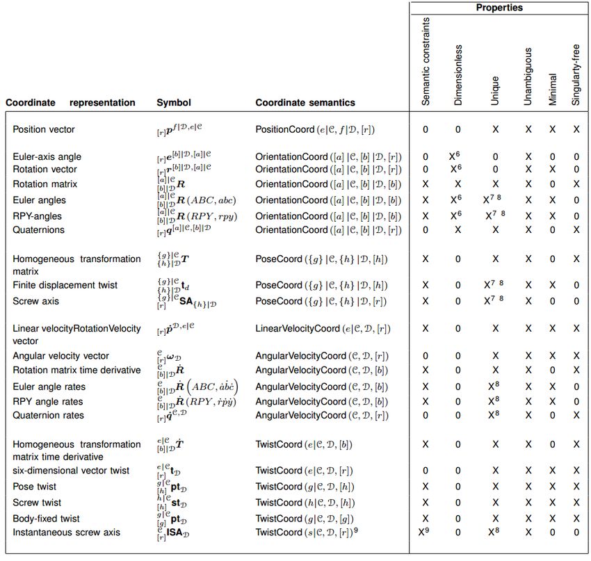
3.4 Coordinate Representation
Coordinate representations express how a geometric concept is mathematically represented, as-
signing to a concept a symbol value, a vector or a matrix with a semantic value. In the contex of
a motion and perception stack, the basic geometric concepts are those relationships that describe
22You can also read