High Temperature Magnetic Sensors for the Hot Section of Aeroengines
←
→
Page content transcription
If your browser does not render page correctly, please read the page content below
aerospace
Article
High Temperature Magnetic Sensors for the Hot Section
of Aeroengines †
Edward Rokicki ‡ , Radoslaw Przysowa *,‡ , Jerzy Kotkowski ‡                              and Paweł Majewski ‡

                                          Instytut Techniczny Wojsk Lotniczych, ul. Ksiecia Boleslawa 6, 01-494 Warsaw, Poland;
                                          edward.rokicki@itwl.pl (E.R.); jerzy.kotkowski@itwl.pl (J.K.); pawel.majewski@itwl.pl (P.M.)
                                          * Correspondence: radoslaw.przysowa@itwl.pl
                                          † This paper is an extended version of our paper published in AVT-357 Research Workshop on Technologies for
                                            future distributed engine control systems (DECS) organized online by the NATO Science and Technology
                                            Organization on 11–13 May 2021.
                                          ‡ These authors contributed equally to this work.

                                          Abstract: Magnetic sensors are widely used in aeroengines and their health management systems,
                                          but they are rarely installed in the engine hot section due to the loss of magnetic properties by
                                          permanent magnets with increasing temperature. The paper presents and verifies models and design
                                          solutions aimed at improving the performance of an inductive sensor for measuring the motion of
                                          blades operated at elevated temperatures (200–1000 °C) in high pressure compressors and turbines.
                                          The interaction of blades with the sensor was studied. A prototype of the sensor was made, and
                                          its tests were carried out on the RK-4 rotor rig for the speed of 7000 rpm, in which the temperature
                                          of the sensor head was gradually increased to 1100 °C. The sensor signal level was compared to
                                          that of an identical sensor operating at room temperature. The heated sensor works continuously
                                          producing the output signal whose level does not change significantly. Moreover, a set of six probes

                                   passed an initial engine test in an SO-3 turbojet. It was confirmed that the proposed design of the
Citation: Rokicki, E.; Przysowa, R.;      inductive sensor is suitable for blade health monitoring (BHM) of the last stages of compressors
Kotkowski, J.; Majewski, P. High          and gas turbines operating below 1000 °C, even without a dedicated cooling system. In real-engine
Temperature Magnetic Sensors for the      applications, sensor performance will depend on how the sensor is installed and the available heat
Hot Section of Aeroengines. Aerospace     dissipation capability. The presented technology extends the operating temperature of permanent
2021, 8, 261. https://doi.org/            magnets and is not specific for blade vibration but can be adapted to other magnetic measurements
10.3390/aerospace8090261                  in the hot section of the aircraft engine.

Academic Editor: Antonios Tsourdos        Keywords: high-temperature sensor; inductive sensor; blade tip timing; blade health monitoring

Received: 17 July 2021
Accepted: 11 September 2021
Published: 13 September 2021
                                          1. Introduction
Publisher’s Note: MDPI stays neutral
                                               The need to monitor the health of the blades of jet engines and stationary turbines
with regard to jurisdictional claims in
                                          results from the well-known problems with blade damage [1] caused by ingested foreign
published maps and institutional affil-   objects or material fatigue. Blade Health Monitoring (BHM) systems have good commercial
iations.                                  prospects, especially in power generation turbines, which are increasingly operated in
                                          the off-design mode due to fluctuating market demand for energy. There are also some
                                          successful examples of on-board BHM systems in aviation, including the TS-11 trainer [2]
                                          and F-35 fighter [3], with magnetic sensors installed in the engine compressing section.
Copyright: © 2021 by the authors.
                                               The digital transformation of aviation requires new robust sensors for engine develop-
Licensee MDPI, Basel, Switzerland.
                                          ment, ground maintenance, and in-flight health management and prediction. Magnetic
This article is an open access article
                                          sensors are better suited for monitoring systems than optical [4] or capacitive sensors [5,6]
distributed under the terms and           because they do not require cleaning, and their signals can be processed using commonly
conditions of the Creative Commons        available electronic systems. However, only sensors with high durability and reliability
Attribution (CC BY) license (https://     are acceptable.
creativecommons.org/licenses/by/               In compressors and steam turbines, blade tip timing (BTT) systems are widely used
4.0/).                                    and mature [7,8], while, in gas turbines, there are still significant technical challenges. This

Aerospace 2021, 8, 261. https://doi.org/10.3390/aerospace8090261                                         https://www.mdpi.com/journal/aerospace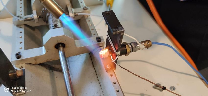
Aerospace 2021, 8, 261                                                                                             2 of 15

                         is due to the low durability and high cost of the suitable probes. The leading engine OEMs
                         spend hundred thousand dollars on a set of sensors needed for a single turbine test.
                                A turbine disk differs significantly from a fan in terms of blade vibration measurement.
                         It is not only in higher operating temperature and dissimilar geometry of the tip but also in
                         the high stiffness of the blades and its different way of supporting the rotor. The deflections
                         of the turbine blades are several dozen times smaller than the fan blades and require
                         measurement systems with a class of higher accuracy and spatial resolution [9]. In addition,
                         the structural resonances of the casing, the axial movement of the shaft, and vibrations of
                         the turbine disk can hinder the blade vibration measurements.
                                BTT and tip clearance (TC) sensors have a lot in common, and some types offer both
                         measurements [10]. However, sensors can be optimized either for clearance or vibration
                         measurement. Due to the demand for higher turbine efficiency, the industry shows more
                         interest in high-temperature TC sensors. Capacity probes are mainly used for this purpose,
                         but several measurement solutions based on active eddy-current principle have been
                         proposed, e.g., Reference [11–13]. Some interesting sensor designs in low temperature
                         co-fired ceramics (LTCC) technology have also been presented [14–16].
                                Permanent magnet inductive sensors known as passive eddy current sensors [17,18]
                         do not have a high-frequency generator and detector. There is, thus, higher bandwidth
                         and no problem with cross-talk and the carrier frequency related to the operation of the
                         generator in active eddy-current sensors [19,20]. The disadvantage of passive sensors is
                         the dependence of the signal on the speed, but this is much less relevant in BTT, especially
                         in constant-speed power generation machines. Tip clearance measurement is also possible
                         but requires dynamic calibration. Another problem is the decrease in magnetization of
                         permanent magnets with increasing temperature. At the Curie temperature, ferromagnetic
                         materials become paramagnetic, i.e., they completely lose their magnetic properties and
                         are no longer a source of a magnetic field. To avoid this, the permanent magnet can be
                         replaced in the sensor with a DC-powered electromagnet [21].
                                Standard inductive sensors measure blade vibrations and rotational speed in machines,
                         such as compressors or steam turbines, where the sensor operating temperature does not
                         exceed 125 °C. Their high temperature versions designed for turbochargers are specified at
                         230 °C [22,23]. However, different sensor materials and manufacturing technologies are
                         required for high pressure compressors and gas turbines. The main difficulty in the design
                         of high-temperature sensors is developing low-temperature sensor production technologies,
                         which, at the same time, guarantee the strength of the structure at an operating temperature
                         of 1000 °C or higher. In particular, it is advisable to use materials and cements that
                         do not need to fire the assembled sensor since this would deprive the magnets of their
                         magnetic properties.
                                Some high temperature BTT sensors (optical and capacitive) are rated for gas temper-
                         atures as high as 1200–1400 °C, but they are designed for short-term use and therefore
                         cannot be used in BHM systems. Moreover, very few other sensors are constantly used
                         in the engine hot section due to the high cost and the lack of materials and technolo-
                         gies to ensure durability. The exceptions include various types of thermometers, such
                         as optical fibers [24,25], Pt100 sensors, and thermocouples, which are usually duplicated.
                         Piezoelectric transducers, such as pressure [26,27] and vibration transducers [28], have a
                         similar problem with the Curie temperature as in inductive sensors, but there is a group of
                         materials that does work above 600 °C [29,30].
                                Microwave sensors [9,31,32] can be made of materials that can be used up to 1400 °C.
                         Unfortunately, changes in distances in the turbine caused by thermal expansion shift
                         the sensor’s operating point, which can be compensated for by using complex electron-
                         ics. Capacitive and optical BTT/TC sensors are more mature than microwave ones, but
                         their electronics are similarly fragile and complex, thus not being ready for in-flight or
                         field operation.
                                The article presents selected design solutions and the results of rig testing of an induc-
                         tive sensor with a permanent magnet, which can operate in gas turbines at a temperature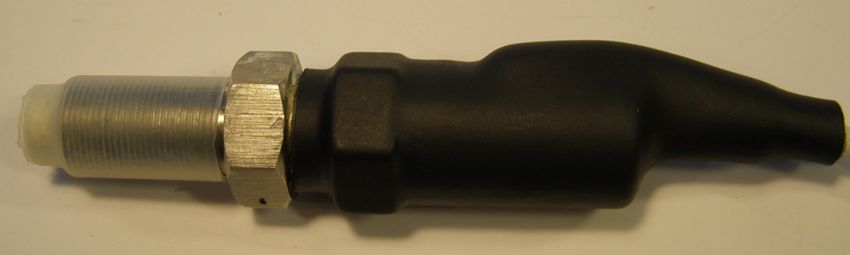
Aerospace 2021, 8, 261 3 of 15
up to 900 °C. A series of measurements was made to verify the suitability of the sensor
for operation in a gas turbine. In order to check the sensor’s performance at elevated
temperature, the head of the sensor was heated with a blowtorch from 25 °C to 1100 °C,
comparing its signal with the response of a cold sensor aimed at the same test wheel.
2. Materials and Methods
2.1. Working Principle
The inductive tip-timing sensor is designed to measure the arrival time of blades
(TOA). Like an electric generator, it uses electromagnetic induction to produce output
signal as blades pass. The sensor consists of a probe and a specialized conditioning
system [33], which can work near the turbine at a temperature as high as 150 °C if it is
made from high temperature electronic components [34]. The design of the probe and
conditioning system must be adapted to the blade material, operating temperature, and
the length of the signal cable. Higher flexibility was achieved here, inter alia, by using
programmable gain amplifiers (PGA).
The field of the sensor is shaped in such a way that it reaches the blade tip. This make
the blade an integral part of the electromagnetic circuit (Figure 1). The diagram illustrates
the electrodynamic interaction between the induced currents in the passing blade i1 and
the sensor winding i2 . Rb and Xrb are the equivalent blade resistance and leakage reactance,
and Rs and Xs are the sensor resistance and reactance. The conditioning system (Figure 2)
includes a current-voltage converter (preamplifier), which produces the voltage output
signal proportional to the sensor current i2 .
1 2 3 4
A
Figure 1. Inductive sensor circuit.
PGA NLPGA
PGA
PIL?02 Vin Vin NLVin
Vin
B COL? NLAO
AO
10uH NL0005V
+/-5V
0.1 om Vref
PIR?01 PIR?02 PIR?01 PIR?02
Vref
PIR?01 PIR?02 PIR?01 PIR?02
NLVref
Vref
PIR?01 PIR?02
COR?
PIR?01 PIR?02
PIL?01
NLpreamplifier
preamplifier NLamplifier
amplifier NLoutput stage
output stage
NL5V TTL
5V TTL
C
NLphase detector
phase detector
Figure 2. Sensor conditioning system.
The quality of the generated signal is related to the waveform parameters, such as
pulse amplitude, rise time, and signal noise ratio [35]. The voltage reaches its maximum
when the maximum energy of interaction between the blade and the sensor occurs [21].
D
Obtaining pulses of the appropriate quality requires the optimizationTitleof the magnetic
Schemat systemu pomiarowego
Size Number
A4
Date: 2021-08-30 Sheet o
File: C:\Users\..\SchemWzm2.SchDoc Drawn B
1 2 3 4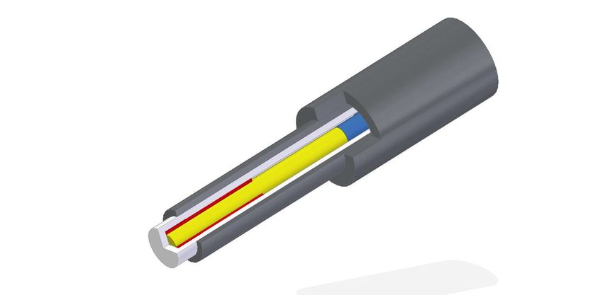
Aerospace 2021, 8, 261                                                                                          4 of 15

                         circuit of the sensor so that the moment of force which it acts on the blade is the greatest.
                         This is especially true if the blade is not ferromagnetic.
                               The range of the sensor should correspond to the variation of tip clearance during
                         machine operation. It must not be too large, especially in turbine where the blades are
                         numerous and relatively densely spaced around the circumference. Then, the sensor
                         interacts with two or three blades at the same time, which reduces the signal quality and
                         resolution of the position measurement.
                               An earlier version of the sensor is presented in Reference [18]. The probe design has
                         recently been modified to improve durability, hot gas resistance, and output character-
                         istics. The solution is based on the patented high-temperature magnetic measurement
                         technology [36] based on the use of a pair of permanent magnets and a winding with a low
                         number of turns. The use of two magnets prevents the decrease in the magnetic properties
                         of the sensor under the effect of exhaust gases. A low-turn winding [37] and related low
                         resistance reduce the impact of temperature on coil impedance and sensor performance. In
                         the presented sensor, the winding has tree turns and a diameter of 7 mm. Its resistance is
                         100 mΩ, and its inductance is 2 µH.
                               The inductive sensor (Figure 1) can detect the rotating blades made of conductive
                         ferromagnetic or non-magnetic materials due to the wide range of gains available in the
                         conditioning system. It can be installed in a threaded hole and fixed with an M16x1 nut.
                         Alternatively, a bracket with a 19-mm hole and two M16x1 nuts (Figure 3) can be used.

                         Figure 3. Inductive sensor with a mounting bracket.

                         2.2. Sensor Design
                              The probe consists of a steel body, a magnetic circuit and a heat-resistant ceramic
                         insulator. The two-piece body is the main structural element of the sensor, designed to
                         operate in the turbine zone under thermal stress and high vibration levels. The steel body,
                         in order to guarantee the sensor’s durability, should have proper walls of appropriate
                         thickness, and the threads used should ensure fastening. Inside, there is an insulator, and
                         inside the insulator-fixed elements of the magnetic circuit, i.e., two magnets and a winding.
                              The insulator is made of ceramics (Al2 O3 99.9% purity), fired in 1600 °C, which can
                         operate in high pressure and temperature existing in gas turbine. Above 300 °C, ceramics
                         becomes a semiconductor whose wave impedance is a function of the concentration of ions
                         in the exhaust gas. Due to the high purity, the wave impedance of the ceramics is then
                         about 120 Ω (not 1 Ω as for the contaminated one). The input impedance of the amplifier
                         and the sensor winding is matched to the wave impedance of the hot insulator.
                              The ceramic insulator protrudes about 10 mm from the steel body. In this temperature
                         range, there are no other materials than ceramics that could act as an insulator. Unfortu-
Aerospace 2021, 8, 261 5 of 15
nately, if it is hit when cold, it can break easily. Due to its fragility, it should be covered as
much as possible by the steel body.
The assembled sensor (Figure 4) cannot be repaired or disassembled without destroy-
ing it. The elements of the electromagnetic circuit inside the sensor cannot move. The
correctness of the assembly or any damage can be checked using Computed Tomography
(CT). You can also measure the winding resistance and the magnetic field of the magnets
with a magnetometer.
The signal cables have glass-fiber insulation with an operating temperature of 800 °C.
The cables can be extended with a standard twisted pair (Ethernet cable) if needed, but this
reduces the signal-to-noise ratio. The maximum possible length (typically 12 m) depends
on the application: the greater the gain, the shorter the cable should be. The operation of
the sensor requires a microprocessor-controlled conditioning system [34], which amplifies
the signal and generates a digital TTL signal.
Figure 4. Inductive sensor-photo.
2.3. Permanent Magnets
Strong permanent magnets (PM) are made from alloys of rare-earth elements [38,39].
Among the available types of magnets, ferrite and neodymium magnets do not work at
temperatures above 200 °C (Table 1). They lose a lot of their magnetic field, even at a
moderate temperature as high as 125 °C [40]. All magnets demagnetize when heated to the
Curie temperature or when a strong electromagnetic field from an AC electromagnet is
applied [41].
Table 1. Permanent magnet properties.
Property Ferrite (HF) AlNiCo SmCo NdFeB
Pull force moderate medium high very high
Curie temp.°C 450 900 750 310
Max. operating temp.°C 250 520 350 100
Corrosion resistance very high very high high low
diamond cutting
Machining no no no
grinding
Demagnetization with
medium-resistant not resistant very resistant resistant
AC electromagnet
Cost low high very high acceptable
The presented sensor uses two cooperating magnets [36]: measuring AlNiCo and
supporting samarium (SmCo)—Figure 5. The magnets are positioned on the sensor axis
along which the temperature gradient occurs. The AlNiCo magnet works at a higher
temperature but is supported by the field of the stronger samarium magnet. This solution
makes it difficult to demagnetize the AlNiCo magnet even though it is operated over the
maximum temperature it is rated for, i.e., 520 °C but below its Curie point. Moreover, the
elevated temperature is a factor that strengthens its field. This phenomenon is also used
in the manufacturing of permanent magnets to improve their performance by applying
strong magnetic fields and elevated temperature in the process known as magnetic thermal
annealing or artificial magnetic aging [42,43].Aerospace 2021, 8, 261 6 of 15
The turbine heats up considerably when the engine is shut down, when airflow
ceases and the structure is not cooled. Such states in sensors with a single magnet causes
their irreversible destruction. In the presented two-magnet sensor, moderate overheating
stabilizes and strengthens the measurement magnet. The signal parameters are maintained
if the temperature of the external part of the sensor does not exceed 400 ºC.
Figure 5. Two magnets and winding inside the sensor.
2.4. Sensor Installation
During operation in a gas turbine, the probe comes into contact with gas at a tem-
perature of up to 1100 ºC. Therefore, it should be mounted in such a way that makes heat
dissipation possible so that the temperature of the external part of the sensor does not
exceed 150–200 ºC during normal operation. The cooling medium may be bleed air or
bypass air in a turbofan.
The sensor is installed manually in the turbine casing. It is mounted by screwing
the sensor into the socket prepared in the engine nozzle to the appropriate distance from
the blade. After positioning the sensor, it is fixed with a nut and connected to the config-
ured amplifier.
Installing the sensor is the riskiest moment for its health and durability, especially for
the cables and the insulator. Personnel handling sensors should be properly trained and
should use the proper tools. The threads should be made so that it is not necessary to use
high torques for fastening. The cables should be carefully fastened in conduits so that they
are not exposed to abrasion and erosion. Fitting sensors requires removing the outer casing
of the engine and usually costs much more than sensors.
2.5. Sensor Durability
Operators are interested in achieving the durability of the sensors at least several
thousand flight hours, which is the typical time between overhaul (TBO) of engines, but
it is difficult to simulate and prove in laboratory conditions. This order of durability was
achieved in steam turbines where the operating temperature is moderate (about 100 °C),
but the main problem is a humid environment and corrosion [44]. In case of mechanical
damage to the insulator, the sensor loses its tightness, and the winding and magnets corrode.
In a damaged sensor, the response of the electromagnetic circuit to the blade transitionAerospace 2021, 8, 261 7 of 15
decreases and gradually disappears, which is manifested by a lower signal-to-noise ratio
of the output signal.
During the operation of a gas turbine, there are noticeable changes in the stand-off
distance between the blades and the sensor due to rotor vibrations and thermal expansion.
This is why the ceramic insulator should be flush-mounted and must not protrude into
the abrasive layer. If the stand-off clearance is too small, the sensor may be rubbed and
damaged [11,18].
Further work is required to predict sensor health and detect symptoms of signal
deterioration. Fernandez et al. [45] tested performance of PMs subjected to cyclic magneti-
zation and demagnetization in temperature up to 135 °C. They found that magnets’ cycle
life decreases with operating temperature. Here, the known methods for assessing the
waveform quality are used, such as monitoring and statistical analysis of pulse amplitude,
signal-to-noise ratio, rise time, and the number of missing and surplus blades.
2.6. Rig Testing
A commercial rotor rig (Bently Nevada RK-4 Rotor Kit) was adapted to test BTT / TC
sensors. A test wheel with 9 steel blades and a diameter of 120 mm was mounted on the
shaft. The motor control unit was used to set the desired speed up to 10,000 rpm. The NI
PXI-1065 computer equipped with PXIe-6358 module and software developed in LabView
was the data acquisition system (DAQ). The block diagram of the measurement system is
shown in Figure 6.
Reference
sensor
Rotor
Electric
motor
Heated
sensor
MATLAB
Amplifier DAQ
Figure 6. Scheme of the rotor rig and data acquisition.
Two sensors were mounted around a test wheel. Figure 7 shows the tested sensor
heated with a blowtorch on the right and the reference sensor in the bottom left corner.
The temperature of the probe was measured with a thermocouple, which was attached to
the ceramic insulator by means of glass silk thread, resistant to temperature up to 1060 °C.
The test consisted of heating the sensor for 3 min until the selected temperature was stable
and measuring the sensor signal at a constant speed of 7000 rpm for 30 s. This procedureAerospace 2021, 8, 261 8 of 15
was repeated a few times for temperature raised from 50 to 1100 °C. The bladed wheel was
moved away from the sensors during heating, but it was moved back for spinning.
1 Reference sensor
6 7 2 Rotor
3 Heated sensor
4 Thermocouple
5 5 Speed sensor
6 Electric motor
7 Blowtorch
3
2 4
11
Figure 7. Inductive probe fired at the rotor rig.
A series of measurements were made with gradually increased temperature (Figure 8).
The signals from the sensors were fed into the multi-stage adjustable amplifier of the
conditioning system. The amplified signals were sampled with frequency of 500 kHz.
For each temperature point, 20 s of data was recorded in the pcm format and processed
in MATLAB.
(a) 500 °C (b) 600 °C
(c) 700 °C (d) 900 °C
Figure 8. Probe at gradually increased temperature.Aerospace 2021, 8, 261 9 of 15
2.7. Signal Processing
For each temperature, the Hilbert transform Hx (t) was calculated for sensor output
x (t), for the data frame of 20 s. It was used to get the signal envelope e(t) as the modulus
of the analytic signal:
e(t) = | x (t) + iHx (t)|. (1)
The average envelope voltage of the hot sensor was then related to the cold sen-
sor’s one.
3. Results
Across the whole tested temperature range (50–1100 °C), both sensors generated
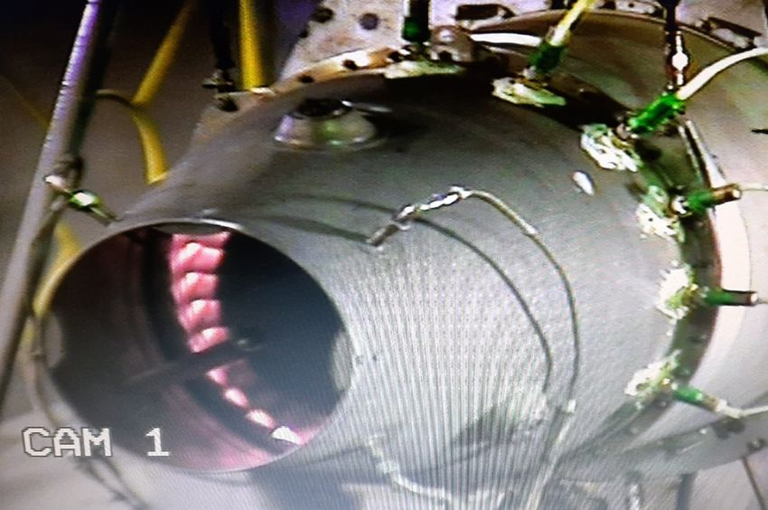
measurable pulses in response to passing blades. Figures 9 and 10 show the heated probe
and its output signal at 1100 °C.
Figure 9. Probe and a thermocouple heated to 1100 °C.
Figure 10. Output signal at 1100 °C.Aerospace 2021, 8, 261 10 of 15
The voltage level of the signal was determined for several temperatures. Figure 11
shows the voltage ratio of the heated sensor signal in relation to the cold sensor. It can be
seen that the sensor maintains its primary performance even at 1100 °C.
Figure 11. Hot sensor output voltage related to cold probe.
Finally, six sensors were installed in the turbine of the SO-3 turbojet and tested
(Figure 12). Output signals were acquired with 1 MHz sampling. All the sensors produced
readable signals for the entire test. Figures 13 and 14 show some initial data gathered at
the idle (7200 rpm) and takeoff speed (15,600 rpm). There are 83 turbine blades, so the
corresponding blade passing frequencies are 9960 Hz and 21,580 Hz. The rising edge has a
low rise time, so it can be used for time-of-arrival measurement.
Figure 12. Sensors operated in a SO-3 turbojet.Aerospace 2021, 8, 261 11 of 15
Figure 13. Sensor 2 output for the SO-3 turbojet at idle.
Figure 14. Sensor 2 output for the SO-3 turbojet at the takeoff speed.
4. Discussion
Presented rig and engine tests confirmed that hot gases had negligible influence on
the sensor output signal. Moreover, these preliminary engine tests verified the correct
operation of a set of sensors installed in the turbine casing. This provides a solid basis for
blade vibration analysis and further studies of turbine dynamics. Our prior measurements
in this turbine were performed with a single microwave sensor [9] or, later, with a previous
version of the inductive sensor [18]. There were considerable difficulties in identifying the
observed vibration responses due to the inability to conduct multi-sensor analysis.
The presented sensor has significant improvements in relation to its previous version.
Firstly, an insulator with much better parameters and a lower production spread was used.
It was possible, thanks to the improvement of the production technology, inter alia, to
reduce shrinkage after firing. Low porosity and high purity and hardness of the ceramics
were achieved. These factors directly affect the durability and performance of the sensor.
Based on operating experience with earlier versions, the geometry of the sensor and
its manufacturing process were fine-tuned. In particular, the magnetic circuit of the sensor
was enhanced by more efficiently matching its impedance with the input impedance of the
amplifier. The implemented method of assembling the circuit and guiding the winding
increased the reliability of the sensor. Thanks to the maturation of sensor’s manufacturing
technology, an acceptable repeatability of its parameters was achieved, which made it
possible to build a multi-probe BTT system. However, sensor optimization has naturalAerospace 2021, 8, 261 12 of 15
limitations related to the turbine environment, such as limited space and problems with
heat dissipation.
The presented rig experiment lacked a screen simulating the turbine casing as in
Reference [11]. As a result, the sensor received more heat than in the engine, which is even
better for checking its robustness. However, the measurement of temperature at only one
point was a significant simplification, especially in view of the temperature gradient along
the sensor needed for its correct operation. This is due to the fact that, in a standard engine,
only the average exhaust gas temperature (EGT) is available. More thermocouples should
be used in the next test, or even a thermal imaging camera. It is also planned to carry out a
numerical thermal analysis of the sensor. To prove the durability of the sensor, a burner rig
should be built, able to perform automatic heat cycles, in which the temperature changes
according to the mission profile of the aircraft engine.
Although a complete thermal analysis of the sensor has not been done, it was con-
firmed that both magnets were not overheated in the presented tests. Firstly, the maximum
turbine inlet temperature, i.e., 800 °C, known from engine specifications, EGT measure-
ment, and performance calculations, is lower than the Curie point of the AlNiCo magnet.
Secondly, a similar sensor was tested with an infrared camera at this engine at the take-off
speed, showing 175 °C at the cold end and 265 °C at the hot end of the sensor. These
numbers are in the operating temperature range of the used SmCo magnet. In addition, no
indication of deterioration of the output signal was observed in the presented tests.
Tests run on a legacy turbojet may seem not quite representative for operation of a
stationary gas turbine or a commercial turbofan engine. Earlier experience with the military
turbofan shows that, in bypass engines, it is more difficult to install and service the sensor,
but there are better conditions for the natural cooling of the sensor. The use of a turbojet in
the engine design is beneficial from the point of view of the cost of testing and the labor
consumption of sensor assembly. However, the presented preliminary tests are insufficient
to validate the reliability and durability of the sensor. Although the earlier version of the
inductive sensor operated in a gas turbine for about 30 h, and at least 3 years in a steam
turbine, it was possible to perform only a short engine test with this sensor design.
As for the data collected during the engine tests, we intend to carry out further analysis
based on objective criteria, both in terms of waveform quality and blade vibration. In
particular, the waveform parameters of the tested sensors in the different operating points
will be compared. An uncertainty analysis will be carried out, which will lead to the
selection of the optimal sampling rate and triggering method and determination of the
arrival times for all sensors. This will enable the blade vibration analysis to be performed
using circumferential least squares [7,46].
It is expected that the acquisition system will be properly set up to generate online
TOA values in planned engine tests. This will enable the characterization of turbine blade
vibrations and the application of external excitation to observe responses that are normally
not measurable. It is planned to equip the engine with a sensor once per revolution and an
accelerometer, which will facilitate the interpretation of tip timing data.
Due to the physical limitations of the technology related to Curie temperature, the
presented magnetic sensors with permanent magnets cannot replace capacitive or optical
sensors used in the development of modern high pressure turbines. However, inductive
sensors can be suitable and cost-competitive in applications where gas temperature is
moderate and where there is no access to a sensor for maintenance. Moreover, active
cooling can significantly extend the scope of their application. The flexibility of using
this type of sensor in the engine and its signal-to-noise ratio was considerably enhanced
by introducing a smart conditioning unit [34], able to monitor and control the output
signal level.
5. Conclusions
The paper presents the design and validation of a high-temperature magnetic sensor
for blade health monitoring. It discusses the selection of components and technologiesAerospace 2021, 8, 261 13 of 15
to build a robust and durable sensor, as well as challenges related to its installation in a
turbine and efforts to ensure trouble-free operation. Its highlights include: using twin
magnet design to extend sensor operating temperature and testing more than one sensor
in parallel on the hot rig and in the axial turbine of the aircraft engine.
The permanent-magnet sensor was tested at a temperature of up to 1100 ºC to evaluate
its waveform quality and confirm the possibility of using it in the BHM systems of gas
turbine blades. It was found that the signal level changes by only a percent as a result of
heating. In real-engine applications, sensor performance will depend on how the sensor
is installed and the available capability for heat dissipation. The proposed design of the
inductive sensor is suitable for blade health monitoring of the last stages of compressors
and gas turbines operating below 1000 °C, even without a dedicated cooling system.
The presented design solutions overcome most problems related to the operation of
inductive sensors in elevated temperature. They can be also implemented in other types of
magnetic sensors used to measure speed or distance in the hot section of the gas turbine.
The increased temperature capability of sensors and their electronics offers more flexibility
in the design of the engine health management and control systems, which can, thus, be
made in a distributed architecture. Robust magnetic sensors which need less wires, power,
and cooling are more likely to be widely implemented in future aircraft engines.
Author Contributions: Conceptualization: E.R. and R.P.; Investigation: J.K., E.R., P.M., and R.P.;
Methodology: E.R., R.P., and P.M.; Project administration: R.P.; Software: R.P. and E.R.; Super-
vision: R.P. and P.M.; Visualization: R.P., J.K., and E.R.; Writing—original draft: R.P. and E.R.;
Writing—review & editing, R.P. All authors have read and agreed to the published version of
the manuscript.
Funding: This publication includes the results of the statutory activity of ITWL ’Demonstrator of
the system to measure turbine blade vibration’, financed by the Ministry of Science and Higher
Education in 2018–2020.
Institutional Review Board Statement: Not applicable.
Informed Consent Statement: Not applicable.
Data Availability Statement: The data presented in this study are available on request from the
corresponding author.
Conflicts of Interest: The authors declare no conflict of interest.
Abbreviations
The following abbreviations are used in this manuscript:
AVT Applied Vehicle Technology Panel
BHM Blade Health Monitoring
BTT Blade Tip Timing
CT Computed tomography
DAQ Data Acquisition system
DC Direct current
DECS Distributed engine control systems
EGT exhaust gas temperature
ITWL Air Force Institute of Technology in Warsaw
LTCC Low temperature co-fired ceramics
NATO North Atlantic Treaty Organization
OEM Original Equipment Manufacturer
PGA Programmable Gain Amplifier
RK Rotor Kit
TC Tip Clearance
TOA Time of Arrival
TTL Transistor–transistor logicAerospace 2021, 8, 261 14 of 15
References
1. Mevissen, F.; Meo, M. A Nonlinear Ultrasonic Modulation Method for Crack Detection in Turbine Blades. Aerospace 2020,
7, 72. [CrossRef]
2. Witos, M.; Szczepanik, R. Turbine Engine Health/Maintenance Status Monitoring with Use of Phase-Discrete Method of Blade
Vibration Monitoring. In RTO-MP-AVT-121 Evaluation, Control and Prevention of High Cycle Fatigue in Gas Turbine Engines for Land,
Sea and Air Vehicles; NATO RTO: Neuilly-sur-Seine, France, 2005; pp. 1–18.
3. Real-Time Fan Blade Damage Detection. Available online: https://www.gastops.com/solutions/aviation/turbine-blade-
condition-indication/ (accessed on 17 July 2021).
4. García, I.; Przysowa, R.; Amorebieta, J.; Zubia, J. Tip-Clearance Measurement in the First Stage of the Compressor of an Aircraft
Engine. Sensors 2016, 16, 1897. [CrossRef] [PubMed]
5. Chivers, J. A Technique for the Measurement of Blade Tip Clearance in a Gas Turbine. In Proceedings of the 25th Joint
Propulsion Conference, Monterey, CA, USA, 12–16 July 1989; American Institute of Aeronautics and Astronautics: Reston,
Virigina, 1989. [CrossRef]
6. Fabian, T.; Prinz, F.B.; Brasseur, G.; Member, S. Capacitive Sensor for Active Tip Clearance Control in a Palm-Sized Gas Turbine
Generator. Instrumentation 2005, 54, 1133–1143. [CrossRef]
7. Przysowa, R.; Russhard, P. Non-Contact Measurement of Blade Vibration in an Axial Compressor. Sensors 2020, 20, 68. [CrossRef]
8. Przysowa, R. Blade Vibration Monitoring in a Low-Pressure Steam Turbine. In Volume 6: Ceramics; Controls, Diagnostics, and
Instrumentation; Education; Manufacturing Materials and Metallurgy; American Society of Mechanical Engineers: Oslo, Norway,
2018; pp. 1–11. [CrossRef]
9. Szczepanik, R.; Przysowa, R.; Spychała, J.; Rokicki, E.; Kaźmierczak, K.; Majewski, P. Application of Blade-Tip Sensors
to Blade-Vibration Monitoring in Gas Turbines. In Thermal Power Plants; Rasul, M., Ed.; InTech: Rijeka, Croatia, 2012;
pp. 145–176. [CrossRef]
10. Yu, B.; Ke, H.; Shen, E.; Zhang, T. A Review of Blade Tip Clearance–Measuring Technologies for Gas Turbine Engines. Meas.
Control 2020, 53, 339–357. [CrossRef]
11. Sridhar, V.; Chana, K.S. Tip-Clearance Measurements on an Engine High Pressure Turbine Using an Eddy Current Sensor. In
Proceedings of the ASME Turbo Expo 2017: Turbomachinery Technical Conference and Exposition, Volume 6: Ceramics, Controls,
Diagnostics and Instrumentation, Education, Manufacturing Materials and Metallurgy, Charlotte, NC, USA, 26–30 June 2017;
ASME: New York, NY, USA, 2017; [CrossRef]
12. Zhao, Z.; Liu, Z.; Lyu, Y.; Gao, Y. Experimental Investigation of High Temperature-Resistant Inductive Sensor for Blade Tip
Clearance Measurement. Sensors 2019, 19, 61. [CrossRef] [PubMed]
13. Borovik, S.; Sekisov, Y. Single-Coil Eddy Current Sensors and Their Application for Monitoring the Dangerous States of
Gas-Turbine Engines. Sensors 2020, 20, 2107. [CrossRef]
14. Lai, Y. Eddy Current Displacement Sensor with LTCC Technology. Ph.D. Thesis, University of Freiburg, Freiburg im Breisgau,
Germany, 2005.
15. Ihle, M.; Ziesche, S.; Gierth, P.; Tuor, A.; Tigelaar, J.; Hirsch, O. Low Temperature Co-Fired Ceramics Technology for Active Eddy
Current Turbocharger Speed Sensors. Microelectron. Int. 2018, 35, 164–171. [CrossRef]
16. Ma, M.; Wang, Y.; Liu, F.; Zhang, F.; Liu, Z.; Li, Y. Passive Wireless LC Proximity Sensor Based on LTCC Technology. Sensors 2019,
19, 1110. [CrossRef]
17. von Flotow, A.; Drumm, M.J. High Temperature, through the Case , Eddy Current Blade Tip Sensors. Sens. Transducers Mag.
(S&T e-Digest) 2004, 44, 264–272.
18. Przysowa, R.; Rokicki, E. Inductive Sensors for Blade Tip-Timing in Gas Turbines. J. KONBiN 2015, 36, 147–164. [CrossRef]
19. Chana, K.S.; Sridhar, V.; Singh, D. The Use of Eddy Current Sensors for the Measurement of Rotor Blade Tip Timing: Development
of a New Method Based on Integration. In Proceedings of the ASME Turbo Expo 2016: Turbomachinery Technical Conference and
Exposition, Volume 6: Ceramics, Controls, Diagnostics and Instrumentation, Education, Manufacturing Materials and Metallurgy,
Seoul, Korea, 13–17 June 2016; ASME: New York, NY, USA, 2016. [CrossRef]
20. Wu, J.; Wen, B.; Zhou, Y.; Zhang, Q.; Ding, S.; Du, F.; Zhang, S. Eddy Current Sensor System for Blade Tip Clearance Measurement
Based on a Speed Adjustment Model. Sensors 2019, 19, 761. [CrossRef]
21. Jamia, N.; Friswell, M.I.; El-Borgi, S.; Fernandes, R. Simulating Eddy Current Sensor Outputs for Blade Tip Timing. Adv. Mech.
Eng. 2018, 10, 168781401774802. [CrossRef]
22. Emerald Insight. Honeywell Introduces High Temperature Magnetic Sensors. Sens. Rev. 2000, 20. [CrossRef]
23. TE Connectivity. Jaquet Turbo Speed Sensor for Commercial and Off-Highway Vehicles. Jaquet HMS-5 DSE 0805. Available
online: https://www.te.com/usa-en/product-CAT-SPS0002.datasheet.pdf (accessed on 13 August 2021).
24. Murugan, M.; Walock, M.; Ghoshal, A.; Knapp, R.; Caesley, R. Embedded Temperature Sensor Evaluations for Turbomachinery
Component Health Monitoring. Energies 2021, 14, 852. [CrossRef]
25. Badamchi, B.; Simon, A.A.A.; Mitkova, M.; Subbaraman, H. Chalcogenide Glass-Capped Fiber-Optic Sensor for Real-Time
Temperature Monitoring in Extreme Environments. Sensors 2021, 21, 1616. [CrossRef]
26. Sadl, M.; Bradesko, A.; Belavic, D.; Bencan, A.; Malic, B.; Rojac, T. Construction and Functionality of a Ceramic Resonant Pressure
Sensor for Operation at Elevated Temperatures. Sensors 2018, 18, 1423. [CrossRef]Aerospace 2021, 8, 261 15 of 15
27. Yang, J. A Harsh Environment Wireless Pressure Sensing Solution Utilizing High Temperature Electronics. Sensors 2013,
13, 2719–2734. [CrossRef]
28. Stevenson, T.; Martin, D.G.; Cowin, P.I.; Blumfield, A.; Bell, A.J.; Comyn, T.P.; Weaver, P.M. Piezoelectric Materials for High
Temperature Transducers and Actuators. J. Mater. Sci. Mater. Electron. 2015, 26, 9256–9267. [CrossRef]
29. Turner, R.C.; Fuierer, P.A.; Newnham, R.E.; Shrout, T.R. Materials for High Temperature Acoustic and Vibration Sensors: A
Review. Appl. Acoust. 1994, 41, 299–324. [CrossRef]
30. Jiang, X.; Kim, K.; Zhang, S.; Johnson, J.; Salazar, G. High-Temperature Piezoelectric Sensing. Sensors 2013, 14, 144–169.
[CrossRef] [PubMed]
31. Zhang, J.; Duan, F.; Niu, G.; Jiang, J.; Li, J. A Blade Tip Timing Method Based on a Microwave Sensor. Sensors 2017, 17, 1097. [CrossRef]
32. Abdul-Aziz, A.; Woike, M.R.; Anderson, R.C.; Aboumerhis, K. Propulsion Health Monitoring Assessed by Microwave Sensor
Performance and Blade Tip Timing. In Proceedings of the SPIE 10973, Smart Structures and NDE for Energy Systems and
Industry 4.0, Denver, CO, USA, 3–7 March 2019; 109730Q; Niezrecki, C., Meyendorf, N.G., Gath, K., Eds.; SPIE: Bellingham, WA,
USA, 2019; p. 25, [CrossRef]
33. Rokicki, E.; Przysowa, R.; Spychala, J.; Szczepanik, R.; Perz, M. Elektroniczny Uklad Pradowego Czujnika Indukcyjnego,
Zwlaszcza do Pomiaru Drgan Lopatek Przeplywowych Maszyn Wirnikowych (Electronic System of Current Inductive Sensor,
Especially for Measurement of Flow Blades Vibrations of Rotor Machines). PL Patent 209634 B1, 2008.
34. Rokicki, E.; Kotkowski, J.; Przysowa, R.; Filipkowski, P. Network of Smart Tip-Timing Sensors in Distributed Blade Health
Monitoring System. Preprints 2021, 1–11. [CrossRef]
35. Hayes, B.C. ISA-RP107.1-201x Tip Timing Waveform Quality; Recommended Practice (Draft); International Society of Automation:
Research Triangle Park, NC, USA, 2016.
36. Rokicki, E.; Spychala, J.; Szczepanik, R.; Majewski, P. Measuring Vibrations of a Turbo-Machine Rotor Blade with the Help of an
Induction Sensor in High Temperature. US Patent 8,125,215 B2, 2012.
37. Rokicki, E.; Spychala, J.; Szczepanik, R.; Majewski, P. Induction Sensor to Measure Vibrations of a Turbo-Machine Rotor Blade.
US Patent 8,240,212 B2, 2012.
38. Coey, J.M. Permanent Magnet Applications. J. Magn. Magn. Mater. 2002, 248, 441–456. [CrossRef]
39. Liu, S. Sm–Co High-Temperature Permanent Magnet Materials. Chin. Phys. B 2019, 28, 017501. [CrossRef]
40. Fernandez, D.; Reigosa, D.; Tanimoto, T.; Kato, T.; Briz, F. Wireless Permanent Magnet Temperature & Field Distribution
Measurement System for IPMSMs. In Proceedings of the 2015 IEEE Energy Conversion Congress and Exposition, ECCE 2015,
Montreal, QC, Canada, 20–24 September 2015; pp. 3996–4003. [CrossRef]
41. de Almeida, A.A.; Landgraf, F.J.G. Magnetic Aging, Anomalous and Hysteresis Losses. Mater. Res. 2019, 22, 1–6. [CrossRef]
42. Sanford, R.L. Permanent Magnets; US Gov. Print. Office: Washington, DC, USA, 1944.
43. Skomski, R.; Zhou, J.; Kirby, R.D.; Sellmyer, D.J. Magnetic Aging. MRS Online Proc. Libr. 2006, 887, [CrossRef]
44. Przysowa, R.; Spychala, J.; Majewski, P.; Rokicki, E. Monitoring of Blade Vibration in a Steam Turbine Power Station. In Dynamics
of Last Stage Low Pressure Steam Turbine Rotor Blades; Rzadkowski, R., Szczepanik, R., Eds.; Instytut Techniczny Wojsk Lotniczych:
Warsaw, Poland, 2017; Chapter 8, pp. 183–204.
45. Fernandez, D.; Martinez, M.; Reigosa, D.; Guerrero, J.M.; Suarez, C.; Briz, F.; Alvarez, C.M.S.; Briz, F. Permanent Magnets Aging
in Variable Flux Permanent Magnet Synchronous Machines. In Proceedings of the 2018 IEEE Energy Conversion Congress and
Exposition (ECCE), Portland, OR, USA, 23–27 September 2018; Volume 56, pp. 236–241. [CrossRef]
46. Liu, Z.; Duan, F.; Niu, G.; Ma, L.; Jiang, J.; Fu, X. An Improved Circumferential Fourier Fit (CFF) Method for Blade Tip Timing
Measurements. Appl. Sci. 2020, 10, 3675. [CrossRef]You can also read