INFLUENCE OF BLOCKAID CHAIRS ON COMPRESSION & OUT-OF-PLANE BEHAVIOUR OF REINFORCED MASONRY WALLS - Dr Tatheer Zahra Dr Hossein Derakhshan 24 Nov 2020
←
→
Page content transcription
If your browser does not render page correctly, please read the page content below
INFLUENCE OF BLOCKAID
CHAIRS ON COMPRESSION
 & OUT-OF-PLANE
 BEHAVIOUR OF
 Dr Tatheer Zahra
 REINFORCED MASONRY Dr Hossein Derakhshan
 WALLS
 24 Nov 2020
Executive Summary

Recent changes in Australian Masonry Standards (AS3700-2018) and Australian National Code of
Construction (NCC-2019) pertaining to the design of reinforced masonry (RM) walls under
compression impress the need of a grout annulus thickness of at least twice the vertical bars
diameter and the need of vertical bar confinement through the 6mm tie bars. Maintaining the
verticality of reinforcement in the middle of the grouted cores and restraining them with the tie bars
are challenging tasks and usually are not followed on construction sites. To deliberate this issue,
BlockAid have designed masonry bar chairs or support chairs to align and restrain the reinforcing
bars in the centre of the cores. This report presents an experimental investigation to ascertain the
performance of BlockAid bar chairs in supporting the steel reinforcing bars embedded in the
reinforced masonry (RM) walls subject to vertical compression and out-of-plane loads. Twelve
(12) wall specimens were constructed and tested – 4 each under concentric compression, eccentric
compression and out-of-plane bending. Five grout cylinders, four single blocks, two ungrouted and
three grouted prisms were also tested for the material characterisation. All construction and testing
was conducted at Queensland University of Technology (QUT) Banyo Pilot Plant Precinct,
Brisbane from August 2020 to October 2020 under a research contract funded by BlockAid Pty
Ltd. The construction and testing procedure for this research was consistent with a previous study
conducted by QUT in 2018 for BlockAid bar chair performance for a different type of block and
the QUT-CMAA (Concrete Masonry Association of Australia) test campaign where the
effectiveness of vertical steel in reinforced masonry walls built without BlockAid under
compression was examined.

The mean compressive strength obtained from the fully grouted RM walls with BlockAid was
determined higher than the strength obtained from the QUT-CMAA research conducted on similar
walls without BlockAid for a different concrete block. Under concentric compression, control
specimen (with 6mm restrainer bars) using 20.42 blocks as per client request sustained maximum
load of 3100kN, while maximum load for the BlockAid sample was 3030kN (only 2.2% lower).
Strain in the vertical steel bars – irrespective of the presence of the BlockAid remained compressive
throughout the loading history with no evidence of buckling; this behaviour is similar to the QUT-
CMAA research. Whereas in eccentric compression, there was no significant difference in the
maximum compressive capacity of the control and BlockAid walls, although the tensile steel strains
in BlockAid walls were observed significantly lower (50% less as per this study) than in the control
specimen with 6mm tie bars in lateral directions. These observations conclude that the BlockAid

 1
bar chairs are effective in restraining the vertical bars against buckling and do not compromise the
capacity under compression loads. Additionally, the comparison of experimental compression
capacities with the AS3700-2018 predictions revealed that the BlockAid walls had sufficient safety
factor (about 2.5 times higher) than the code predicted values.

The out-of-plane test results of BlockAid walls and the control walls (without any chairs) were
similar in terms of failure modes, load-displacement behaviour and steel strain variations. The
maximum out-of-plane load capacity of BlockAid walls was 383kN and the control wall was
364kN with similar level of ductility.

In conclusion, it can be stated that the use of BlockAid bar chairs makes the construction process
of the RM walls more efficient, has no obvious adverse effects on the load carrying capacity and
the strain in the reinforcing steel of the RM walls under concentric and eccentric compression and
out-of-plane loads. The successful results in this report are expected to increase the use of BlockAid
bar chairs in the construction of structural reinforced masonry walls.

 2
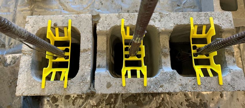
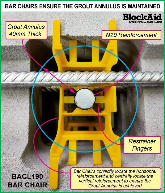
1 Introduction
BlockAid bar chairs are designed to accurately position the horizontal and vertical reinforcement
in reinforced masonry block walls. According to recent revisions in Australian Masonry Standards
(AS3700-2018), the vertical bars should be placed in the centre of grouted cores as such an annulus
grout thickness not less than twice the diameter of vertical reinforcing bars should be maintained
for considering the contribution of vertical bars in the compression capacity. To achieve this
compliance, it is necessary that the vertical bars remains straight and central in the block cores
when the grout is poured. BlockAid bar chairs provide an effective solution to keep the bars straight
in the required position under compression loads as shown in Figure 1. An experimental study was
conducted at QUT in 2018, in which RM walls were constructed using BlockAid bar chairs for
maintaining the annulus grout requirements around the bars and were tested under concentric and
eccentric compression. It was concluded that the bar chairs maintained the grout annulus
requirements without any adverse effect on the compression capacity of the walls. However,
Australian National Code of Construction (NCC-2019) requires RM members in compression to
be restrained by 6mm diameter round bars to laterally restrain the vertical reinforcement in addition
to the annulus grout diameter requirements. Practically, this kind of lateral arrangement is not very
efficient and is generally not followed on construction sites due to the large amount of time required
to restrain the vertical bars laterally using 6mm tie bars. Consequently, BlockAid have revised their
chair design with two restrainer fingers to snug fit the vertical bars and restrain them laterally as
shown in Figure 1.

 Figure 1: BlockAid bar chair to maintain the minimum grout annulus requirement

 3

BlockAid bar chairs are designed for both “Non-Centrally Located (BANCL)” and “Centrally
Located (BACL)” reinforcements, with the vertical steel location determining the correct product
for the application as shown in Figure 2. Non-centrally located bar chairs are designed to support
the vertical and horizontal bars to resist out-of-plane bending especially in the retaining masonry
wall structures. The BlockAid bar chairs are made of plastic and come in sizes suitable to either
190mm or 290mm thick walls; this research has used 190mm thick blocks commonly available in
Queensland. The aims of this research are:

 1- To examine experimentally whether the improved version of BlockAid bar chairs for
 centrally located bars through the grout annulus around the vertical compression steel can
 restrain the bars laterally without compromising the compression capacity of the walls in
 concentric and eccentric compression loads.
 2- To ascertain the out-of-plane capacity of RM walls with BlockAid bar chairs for the non-
 centrally located vertical and horizontal bars.

 (a) BACL190 (b) BANCL190

 Figure 2: Types of BlockAid bar chairs

To achieve these aims, a test scheme was designed to test the RM walls under compression and
out-of-plane loads to ascertain the benefits of the novel BlockAid bar chairs. Twelve medium high
walls with a limited effect of slenderness were constructed – of which four each were tested under
concentric compression, eccentric compression and out-of-plane bending. One undergrad student
under the supervision of a research assistant carried out all laboratory experimental activities. To
prove the hypothesis that the intrusion of the BlockAid bar chairs are expected to exhibit beneficial
effect on the response of masonry walls to axial compression (concentric and eccentric) and out-
of-plane bending behaviours, wall samples without bar chairs having 6mm diameter restrainer bars

 4
under compression while tie wires were used to tie the horizontal and vertical bars to test under
bending for comparison. In addition, the strains in the reinforcing bars were also measured to
examine any premature buckling and effect of restraining provided by the BlockAid bar chairs. The
results of these tests are presented in this report.

2 Experimental Program
In total, twelve block walls were constructed by a professional mason, of which nine (9) walls were
built with BlockAid bar chairs in every alternative bed joints. The remaining specimens were built
without bars chairs as control specimens with standard 6mm diameter restraining bars in
compression, while tie wires were used to tie the horizontal and vertical bars to test under out-of-
plane bending. More details are presented in the following sub-sections.

2.1 Construction materials and properties
For the construction of the walls, grout, blocks, mortar, reinforcement bars were required. All
individual materials were tested for their properties.

2.1.1 Grout
Grout was ordered from Excel Concrete Pty Ltd. The ordered mix was a 25MPa Grout with 220mm
slump and 7mm aggregate. A slump test was conducted to ensure the slump was as prescribed –
the slump tested on site was 230mm. Five Grout Cylinders (100mm diameter × 200mm high) were
also filled in three layers, with 25 tamps at each layer. These cylinders were then tested after 28
days of curing as shown in Figure 3(a). A 2000kN INSTRON machine was used to apply a uniform
compression displacement at the rate of 1mm/min. Grout strength is presented in Table 1.

 Table 1: Grout cylinder test results
 Sample # Compressive strength (MPa)
 1 36.53
 2 41.11
 3 36.15
 4 33.73
 5 33.09
 Mean 36.12
 COV 9%

2.1.2 Blocks
175 full (20.42) and 175 half (20.43) Adbri Blocks were sourced. Four full blocks were randomly
selected and tested to determine the compressive strength consistent with AS/NZS 4456 (2003).
These blocks were tested under face-shell loading by placing 40mm wide × 6mm thick plywoods

 5
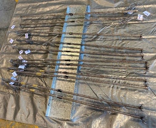
along the full length of the block (390mm) as shown in Figure 3(b). The test results are listed in
Table 2.

 Table 2: Masonry blocks test results
 Sample # Compressive strength (MPa)
 1 15.79
 2 15.34
 3 14.46
 4 15.99
 Mean 15.39
 COV 4%

 (a) Grout test (b) Block test

 Figure 3: Testing of grout and blocks

2.1.3 Mortar
M3 Mortar in the mix ratio of cement (1): lime (1): sand (6) was used for the construction of the
stack bonded prisms and the RM walls. The mortar was supplied and applied by the masons from
‘Templeton Brick Laying’.

2.1.4 Reinforcing Bars
Reinforcing bars (16mm diameter – N16 and 12mm diameter – N12 normal ductility deformed
bars) were sourced from Mesh & Bar Pty Ltd. The reinforcement bars were visually inspected upon
delivery to ensure the straightness and quality of these bars. The bars are shown in Figure 4(a). To
avoid direct contact between the steel loading platen and the reinforcement bars, the vertical
reinforcement bars were welded to a four-legged steel chair which was 25mm high. At the top, the
steel bar finished 25mm lower than the top surface of the masonry wall specimen. This was to

 6

ensure direct contact between the loading platens and the bars was avoided to prevent bowing as
shown in Figure 4(b).

 (a) Prepared bars (b) Bars welding (c) Strain gauging

 (d) Bars testing (e) Tensile stress-strain curves of bars

 Figure 4: Reinforcing bar preparation and testing

The preparation of the reinforcement is vital to the success of the project’s testing. Each wall had
three 1340mm long vertical reinforcement bars at 190mm c/c spacing. All loaded walls had strain
gauges. Four walls had two strain gauges on only the middle vertical reinforcement, whilst the
other walls had two strain gauges on all three vertical reinforcement bars. The strain gauges were
installed at around mid-height (670mm) at front and far face of the bars as shown in Figure 4(c).

Prior to installing the strain gauges, the steel bar was milled to an adequate depth where the surface
was flat enough. Cyanoacrylate was applied onto the sticky tape with the strain gauge and pressure
was applied for 60 seconds to keep the gauge attached onto the bar. Polymer resin coating was then
applied on top of the gauges as a protective layer. Additionally, a hot glue gun was used to seal the
strain gauges at a cool temperature. Finally, the strain gauges were sealed by black silicone for
waterproofing, mechanical protection and insulation. The tensile testing of bar samples is shown

 7
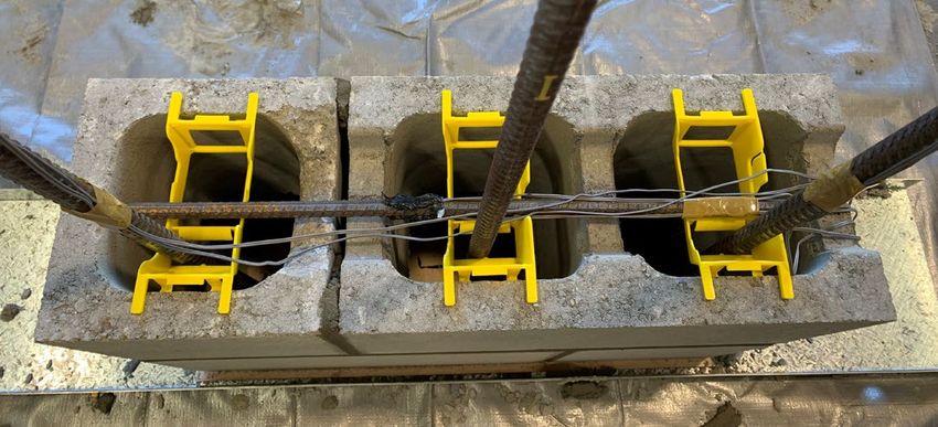
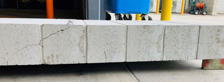
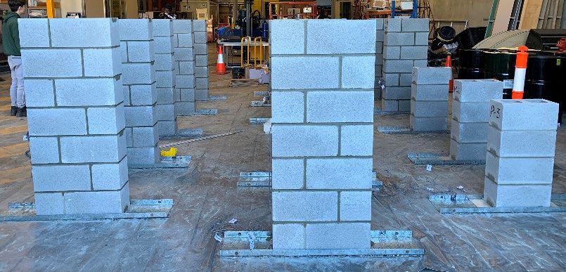
in Figure 4(d) and the stress-strain curves of three tested N16 bars are shown in Figure 4(e). The
yield stress of bars was determined as 550 MPa on an average.

2.1.5 Masonry Prisms
Four courses high stack bonded ungrouted and grouted masonry prisms of size 390mm (long) ×
790mm (high) × 190mm (th.) were constructed using the chosen blocks and mortar; three of them
were grouted. Testing of prisms was consistent with Appendix C of AS3700 (2018). Results are
shown in Table 3.

 Table 3: Masonry prisms test results
 Sample # Ungrouted prism Grouted prism
 strength (MPa) strength (MPa)
 1 8.65 26.99
 2 9.40 23.35
 3 - 25.64
 Mean 9.02 25.33
 COV 6% 7%

2.2 Construction of walls
For compression tests, eight (8) RM walls were developed in the QUT lab for compression loads
without any eccentricity (i.e. concentric compression) and with eccentricity. Three (3) walls each
for concentric and eccentric compression testings were built with BlockAid bar chairs while two
control specimens with 6mm restrainer bars were developed for comparison. For out-of-plane
testing, four (4) RM walls were developed with one wall as 'control' without BlockAid bar chairs
and 3 walls with BlockAid bar chairs in every alternative bed joint. Testing scheme for all the tests
is presented in Table 4. Individual blocks, grout cylinders and grouted prisms were also tested to
characterise the materials under compression.

A professional mason from Templeton Bricklaying was hired to construct all the walls. The
construction of the walls began with a galvanised steel channel as the base. This channel simplifies
the process of moving the walls from the fabrication mat to the loading frame. A 6mm thick
plywood was placed centrally onto the steel channel and the first layer of blocks were positioned
on the plywood. The desired location of the steel bars was marked on the plywood with a marker
aligning through the plastic bar chairs, then the N16 steel vertical bars welded onto a steel chair
were positioned at the marked location. Wall ties and plastic bar chairs were used according to the
wall specification, with wall ties being applied on every block layer as shown in Figure 5(a) and

 8
plastic bar chairs were placed on every second course as can be seen in Figure 5(b). For out-of-
plane bending samples, the same procedure was adopted for construction, except the BANCL190
bar chairs were used with 3 N16 vertical bars and 3 N12 horizontal bars in the tension side as shown
in Figure 5(c) and 5(d) for the control and BlockAid samples. Strain gauge wires were carefully
extracted all towards one end of the wall and escorted through a hole before sealing the hole up
with grouting. Prior to grouting, water was poured in the wall specimen to ensure the grout
smoothly filled up the cores. The constructed samples are shown in Figure 5(e).

 Table 4: Testing Scheme of RM walls

 # Specimen type Test description # of
 samples
 1 RM wall: 590mm (long) × 1390mm (high) Concentric compression test with 1
 × 190mm (th.) [control sample with 6mm strain gauges in all 3 N16 vertical bars
 tie bars]
 2 RM wall: 590mm (long) × 1390mm (high) Eccentric compression test with strain 1
 × 190mm (th.) [control sample with 6mm gauges in all 3 N16 vertical bars (e =
 tie bars] t/3)
 3 RM wall: 590mm (long) × 1390mm (high) Concentric compression test with 3
 × 190mm (th.) [with bar chairs for strain gauges in all 3 N16 vertical bars
 centrally located bars]
 4 RM wall: 590mm (long) × 1390mm (high) Eccentric compression test with strain 3
 × 190mm (th.) [with bar chairs for gauges in all 3 N16 vertical bars (e =
 centrally located bars] t/3)
 5 RM wall: 590mm (long) × 1390mm (high) 4-point bending test with strain 3
 × 190mm (th.) [with bar chairs for non- gauges in all 3 N16 vertical and 3 N12
 centrally located bars] horizontal bars
 6 RM wall: 590mm (long) × 1390mm (high) 4-point bending test with strain 1
 × 190mm (th.) [control with tying wires] gauges in all 3 N16 vertical and 3 N12
 horizontal bars

 9
(a) Control specimen for (b) Specimen for compression
 compression with 6mm tie with BACL190 chairs

 (c) Control specimen for (d) Specimen for bending with
 bending with tie wires BANCL190 chairs

 (e) Constructed walls and prisms

 Figure 5: RM walls construction details

2.3 Testing of walls
The samples were cured for 28 days after pouring of grout. The tests were carried out as per the
scheme provided in Table 4. Instrumentation was implemented to measure the deformations and
strains when the specimens were subjected to loads to determine if unrestrained bars and/or
restrained bars had any dislodgement or otherwise affecting the walls behaviour. Strain gauges
were attached to the vertical and horizontal steel bars for measuring the steel strains. Individual test
details for compression and out-of-plane bending are in the following sub-sections.

 10
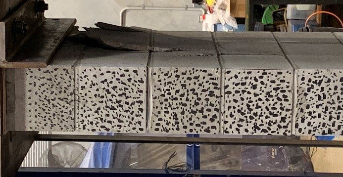
2.3.1 Compression Tests

All RM wall samples were tested in a 4000kN capacity compression testing frame under uniform
compression at the rate of 1mm/min. The test set-up for concentric and eccentric compression are
shown in Figure 6. The steel strains in the proximity of chairs were measured and the capacity of
walls was compared with similar walls previously tested in QUT with 6mm diameter restraining
bars in both lateral directions without any chairs. Deflection and failure mode were also measured
through digital image correlation (DIC) technique. DIC is a unique technique in which the surface
of samples is speckled with black dots and monochrome images of samples are captured at a regular
interval (5 frames per second for this project) during the test. The images are then correlated using
a DIC software to calculate the strain and deformation field with respect to the first image of sample
without any load.

 (a) Concentric compression (b) Eccentric compression

 Figure 6: Compression test details

For eccentric compression tests, the eccentricity of one-third of thickness (t/3) which corresponds
to 63mm was adopted for two samples with BlockAid bar chairs, while one of the samples was
tested for the eccentricity of t/6 = 32mm.

 11
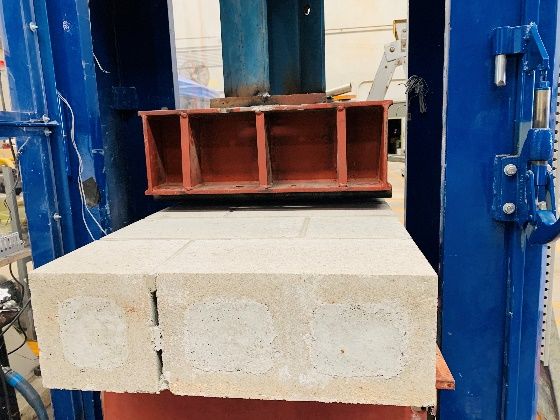
2.3.2 Out-of-plane Bending Tests

Out-of-plane bending tests were also conducted in the same machine with a different loading set-
up. Four-point loading assembly was developed as shown in Figure 7 to apply the out-of-plane
bending loads on the RM wall specimens.

 (c) Side view of test wall
 Figure 7: Out-of-plane bending test details
The deflections under out-of-plane bending tests were measured using three linear variable
displacement transducers (LVDTs) as shown in Figure 7. Similar to compression tests, the steel
strains were also measured through the installed strain gauges in the horizontal and vertical bars.

 12
3 Results and Discussion
The behaviour of tested walls was examined in terms of failure modes, failure strengths, load-
displacement curves and steel strain variations. The results are discussed in detail in this section.

3.1 Compression test results

The general failure mode observed in the concentrically loaded walls was vertical splitting of the
face and web shells. These cracks became evident once the loading reached close to 80% of the
peak load. As the load reached ultimate capacity, these cracks became larger until the walls failed
by crushing of concrete near mortar joints and web splitting as shown in Figure 8(a). Under
eccentric loads, the failure of walls occurred due to opening of mortar joints at tension side and
crushing of concrete on the compression face (see Figure 8(b)). The failure mode is consistent with
the previous tests conducted in 2018 and in QUT-CMAA test campaign for the revisions in
AS3700-2018 version.

 (a) Crushing failure in (b) Joint opening in
 concentric compression eccentric compression

 Figure 8: Failure modes under compression

 13
The maximum (peak) loads for the tested walls under concentric and eccentric compression tests
are summarised in Table 5.

 Table 5: Peak load capacity for compression tests
 Sample # Concentric Eccentric compression
 compression capacity capacity (kN)
 (kN)
 Control 3100 920 (e = 63mm)
 BlockAid 1 2814 926 (e = 63mm)
 BlockAid 2 2504 866 (e = 63mm)
 BlockAid 3 3031 2041 (e = 32mm)

The mean strength of BlockAid wall samples under concentric compression was determined as
2785 kN with a COV of 10% while under eccentricity of e = 63mm as 896 kN (COV – 5%). It can
be observed that the difference of maximum concentric compression strength between the control
wall with standard 6mm restrainer bars (3100 kN) and BlockAid wall (3031 kN) is only 2.2%
which would be lesser if more control wall specimens would have been tested for an average
strength. Whereas under eccentric compression the maximum capacities are almost same for the
control and BlockAid samples.

It is important to mention that these results are much higher than the similar walls tested in 2017
for QUT-CMAA research where the average concentric compression capacity of 1237 kN and
eccentric compression capacity of 610 kN was obtained. The reason for such a large difference (2
folds) can be attributed to the difference in materials strength including block strength (12% higher)
and grout strength (44% higher) for the current tests.

Additionally, the experimental compression capacities were also compared with the predictions of
AS3700 (2018) for compression strength using the design capacity Equation (1).

 ′ )
 (0.55+0.005
 ′

 ≤ � ′ + � 1.3� + � (1)

The mean strength of masonry ( = 9 ), mean strength of grout ( = 36 ), yield stress
of steel ( = 550 ), steel bar area ( = 600 2 ), bedding area ( = 600 × 30 × 2 =
36000 2 ), grout area ( = 58500 2 ), grout strength factor ( = 1.2) and = 0.4 for
RM walls were input in Equation (1). The reduction coefficient was calculated using Equation
(2) separately for concentric and eccentric compression capacities.

 14
 = (1.0 − 0.025 )(1.0 − 2.0 ⁄ ) (2)

 190
The slenderness and eccentricity ratios in the above equation were set as = 1390 = 7.32 and =
 63
0 190 = 0.33 for concentric and eccentric compression, respectively. The results are tabulated

in Table 6.

 Table 6: Compressive capacity comparison with AS3700-2018
 Case Concentric Eccentric compression
 compression capacity capacity (kN)
 (kN)
 Experimental mean 2783 896 (e = 63mm)
 strength
 AS3700 (2018) 1020 340 (e = 63mm)
 prediction
 Ratio = Exp/AS3700 2.73 2.63

The experimental results have yielded a higher strength in comparison to the latest code predictions
which shows the effectiveness of BlockAid bar chairs in restraining the vertical bars. These results
show that with the use of BlockAid bar chairs, the walls can exhibit adequate margin for the safety
factor to account for uncertainties in construction and materials quality.

Load displacement curves and steel strain variations were also measured to verify any buckling or
dislodgement of the bars. Typical results of the control specimens and BlockAid specimens under
concentric compression are presented in Figure 9. It can be observed from the load displacement
curves that the behaviour of control walls and BlockAid walls is quite similar with similar peak
and post peak trends. The steel strain variations with increasing displacement are also very similar
for both kind of samples with maximum compressive strain of around 1200 microstrain (lesser than
the yield strain of 2500 microstrain) in vertical bars which is in agreement to QUT-CMAA test
results for similar walls.

Figure 10 shows the load deflection and steel strain variations of the eccentric wall samples. Again,
the similarities in the load-displacement trends can be observed. However, the steel strains under
eccentric compression in the BlockAid walls were found much lower than the control walls,
perhaps due to restraint provided by the chairs against tension in bars under eccentricity.

 15
(a) Load-displacement curve of control wall (b) Load-displacement curve of BlockAid wall

 (c) Strain variation in control wall (d) Strain variation in BlockAid wall
 Figure 9: Load displacement and steel strains under concentric compression

(a) Load-displacement curve of control wall (b) Load-displacement curve of BlockAid wall

 (c) Strain variation in control wall (d) Strain variation in BlockAid wall

 Figure 10: Load displacement and steel strains under eccentric compression

 16
3.2 Out-of-plane bending test results

For all tested walls under out-of-plane bending, similar failure mode was observed with cracking
at the points of load application as marked in Figure 11. The cracking was symmetric about the
centreline of the wall specimen. The inclined cracking protruded from the point of load applications
to the bottom side of the specimen. Vertical cracks in tension side of the tested walls were also
observed.

 Figure 11: Failure mode of walls under out-of-plane bending
The ultimate strength or load capacity of walls under bending is listed in Table 7. The ultimate load
of the control specimen was measured only 2.5% higher than the mean strength of the BlockAid
wall specimens which is consistently same as in compression tests. The ultimate deflections for
both kind specimens were around 9mm.

 Table 7: Ultimate load capacity for bending tests
 Sample # Ultimate load (kN) Failure deflection
 (mm)
 Control 364 9.1
 BlockAid 1 383 9.4
 BlockAid 2 337 10.2
 BlockAid 3 344 8.1
 Mean 355 9.2
 COV 7% 11%

Figure 12 shows the load deflection and steel strain variations in the horizontal and vertical bars.
The load-deflection behaviour of the control wall and BlockAid walls was found similar. The
measured steel strains in the vertical bars under bending were observed closer to the yield strains
for all bars in all tested walls, while strains in the horizontal bars were much lower at around 250
microstrain due to not directly bending under loads. The vertical steel bars which were

 17
predominantly experiencing tension almost reached the yielding strain but did not undergo higher
than yielding strains due to cracking progression in the masonry.

 (a) Load displacement curves (b) Vertical steel strains in control walls

 (c) Vertical steel strains in BlockAid walls (d) Horizontal steel strains

 Figure 12: Load displacement and steel strain variations for bending tests

4 Conclusions
This research report presents an investigation on the behaviour of RM walls with novel BlockAid
bar chairs installed to support and restrain the reinforcing bars to achieve compliance with AS3700
(2018) and NCC (2019). In total, 12 samples were tested under concentric compression, eccentric
compression and out-of-plane bending loads. Based on the construction and testing of these RM
walls, the following conclusions have been made:

1. The use of BlockAid bar chairs ensures the straightness and correct positioning of the vertical
reinforcement as desired in the compression design provisions of AS3700-2018.

2. Under the test regime, no adverse effect on the load carrying capacity of the RM walls under
compression and out-of-plane loading was obvious.

 18
3. The variation of steel strain under concentric compression loads show no difference between the
control walls with 6mm restrainer bars and the walls with BlockAid bar chairs. However, under
eccentric compression, the tensile strains in bars with bar chairs were much lower than the control
wall showing the effectiveness of bar chairs in restraining the vertical bars against excessive
bending.

4. The compression capacity of tested walls was determined around 2.6 folds higher than the
AS3700 (2018) predictions which can be considered as a factor of safety which demonstrates that
the BlockAid bar chairs can provide adequate safety against uncertainties in construction and
material quality.

5. Out-of-plane bending behaviour of RM walls with and without bar chairs were similar in terms
of steel strains and load displacement responses. This also proves that the BlockAid bar chairs can
be effectively used to restrain/support the vertical and horizontal bars in the retaining structures
without the need of wire tying the horizontal and vertical bars.

The results in this report show that the use of BlockAid bar chairs can expediate the construction
of RM walls with adequate restraint and correct positioning of reinforcing bars within the grouted
cores to efficiently achieve compliance to AS3700 (2018) and NCC (2019).

Bibliography

BlockAid. (2020). Achieving AS3700 compliance in reinforced masonry block wall construction.
BlockAid Pty Ltd.

Dhanasekar, M. (2016). An Investigation of the Effectiveness of the Vertical Steel in Reinforced
Masonry under Compression. Brisbane: Queensland University of Technology.

AS 3700 (2018) Design of Masonry Structures, Standards Australia.

 19
You can also read