MicroRAETM User's Guide - Wireless Personal Four-Gas Monitor - Honeywell
←
→
Page content transcription
If your browser does not render page correctly, please read the page content below
MicroRAE
                      TM

Wireless Personal Four-Gas Monitor
           User’s Guide

                                         Rev. G
                                    August 2019
                               P/N M03-4001-000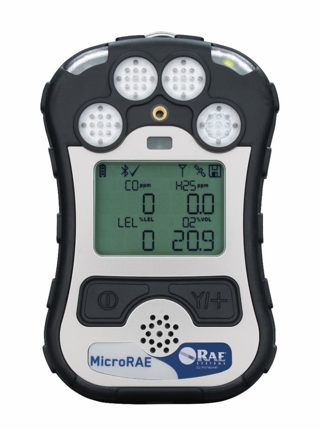
Product Registration
Register your product online by visiting:
http://www.raesystems.com/support/product-registration
By registering your product, you can:

    •   Receive notification of product upgrades or enhancements
    •   Be alerted to Training classes in your area
    •   Take advantage of Honeywell special offers and promotions

                  IMPORTANT! BUMP TEST THE MONITOR
                       BEFORE EACH DAY’S USE
Prior to each day’s use, every gas detection monitor should be bump tested to confirm the
response of all sensors and activation of all alarms by exposing the monitor to a concentration of
target gas that exceeds the low alarm set point. A bump test is also recommended if the monitor
has been subjected to physical impact, liquid immersion, an Over Limit alarm event, or custody
changes, or anytime the monitor’s performance is in doubt.

To ensure greatest accuracy and safety, only bump test and calibrate in a fresh air environment.

The monitor should be calibrated every time it does not pass a bump test, but no less frequently
than every six months, depending on use and exposure to gas and contamination, and its
operational mode.

    • Calibration intervals and bump test procedures may vary due to national legislation.
    • Honeywell recommends using calibration gas cylinders containing the gas that is
      appropriate to the sensor you are using, and in the correct concentration.

© 2019 Honeywell International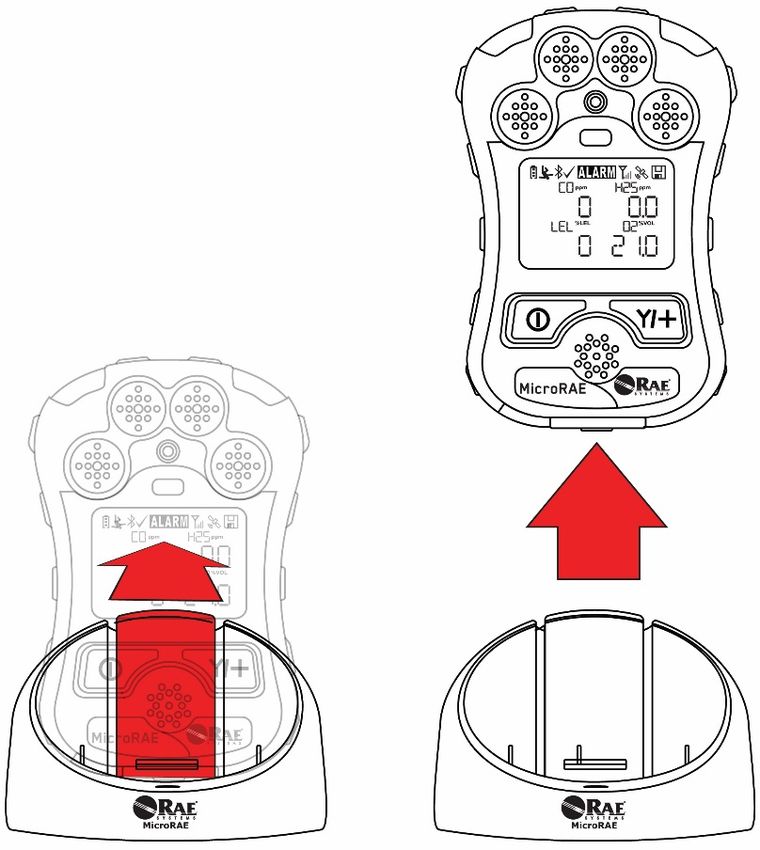
MicroRAE User’s Guide
Contents
1. Standard Contents ..................................................................................................................... 10
2. General Information ................................................................................................................... 11
3. User Interface ............................................................................................................................ 12
3.1. Display Overview ............................................................................................................ 12
3.1.1. Status Indicator Icons ........................................................................................... 12
3.1.2. Keys & Interface .................................................................................................... 14
3.2. Screen Display For Various Numbers Of Active Sensors .............................................. 14
3.3. Menus ............................................................................................................................. 15
3.4. Glance Mode ................................................................................................................... 16
3.5. Panic Alarm ..................................................................................................................... 16
3.6. Confidence LED .............................................................................................................. 16
4. Mesh Wireless Control And Submenus ..................................................................................... 17
5. Battery Charging ........................................................................................................................ 18
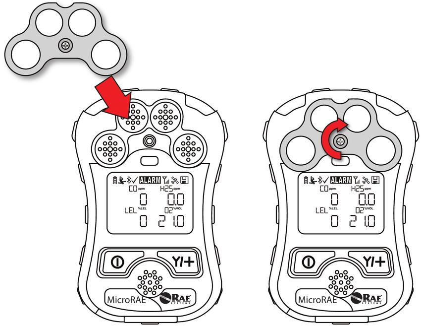
6. External Filter............................................................................................................................. 21
7. Turning The MicroRAE On And Off ........................................................................................... 22
7.1. Turning The MicroRAE On.............................................................................................. 22
7.2. Turning The MicroRAE Off.............................................................................................. 22
7.3. Testing Alarm Indicators ................................................................................................. 23
7.4. Glance Mode ................................................................................................................... 23
7.4.1 Enter Glance Mode ................................................................................................ 23
7.4.2 Screens .................................................................................................................. 24
7.4.3 Exit Glance Mode .................................................................................................. 24
7.5. Comfort Beep .................................................................................................................. 24
7.6. Man Down Alarm ............................................................................................................ 24
7.6.1 Parameter Settings And Sequence Of Events ...................................................... 25
8. Modes Of Operation .................................................................................................................. 28
9. Programming ............................................................................................................................. 28
9.1. Enter Programming In Basic Mode ................................................................................. 28
9.2. Enter Programming In Advanced Mode.......................................................................... 29
9.3. Menus And Submenus.................................................................................................... 29
9.3.1. Calibration ................................................................................................................... 30
9.3.2. Sensor On/Off ............................................................................................................. 31
9.3.3. Clear Datalog .............................................................................................................. 32
9.3.4. Monitor Setup.............................................................................................................. 32
9.3.4.1. GPS On/Off .............................................................................................................. 32
9.3.4.2. Set User ID .............................................................................................................. 32
9.3.4.3. Set Site ID ................................................................................................................ 32
9.3.4.4. Set Radio ................................................................................................................. 33
9.3.4.5. BLE On/Off............................................................................................................... 33
9.3.4.6. Wi-Fi On/Off ............................................................................................................. 33
9.3.4.7. NB-IoT On/Off .......................................................................................................... 33
9.3.4.8. Sent History ............................................................................................................. 33
9.3.4.9. Roaming On/Off ....................................................................................................... 33
9.3.4.10. Radio On/Off .......................................................................................................... 33
9.3.4.11. Set PAN ID............................................................................................................. 34
9.3.4.12. Set Channel ........................................................................................................... 34
9.3.4.13. Join Network .......................................................................................................... 34
9.3.4.14. Factory Reset......................................................................................................... 35
9.3.4.15. Exit ......................................................................................................................... 35
9.4. Parameters Accessed Through ProRAE Studio II .......................................................... 36
9.4.1. Alarm Mode ................................................................................................................. 36
10. Policy Enforcement .................................................................................................................. 38
11. Setting Wi-Fi Parameters ........................................................................................................ 41
11.1. Setting Wi-Fi Parameters In ProRAE Studio II ............................................................... 41
11.1.1. Wi-Fi Power .............................................................................................................. 43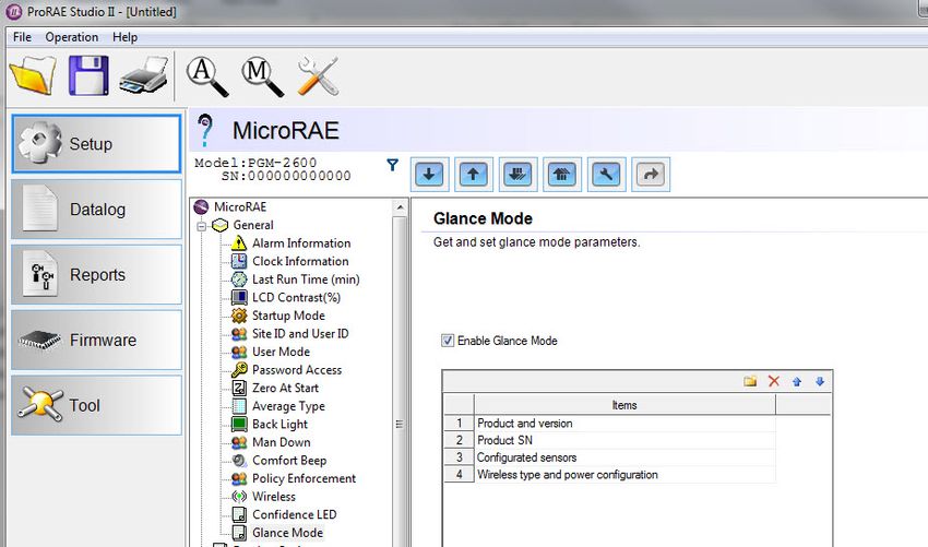
MicroRAE User’s Guide
      11.1.2. MAC Address ............................................................................................................ 43
      11.1.3. Address ..................................................................................................................... 43
      11.1.4. Mode ......................................................................................................................... 44
      11.1.5. Scan Channel List ..................................................................................................... 44
      11.1.6. Security Mode ........................................................................................................... 44
      11.1.7. Security Key .............................................................................................................. 44
      11.1.8. SSID .......................................................................................................................... 45
      11.1.9. Server IP ................................................................................................................... 45
      11.1.10. Server Port .............................................................................................................. 45
      11.1.11. Upload Wi-Fi Settings To The MicroRAE ............................................................... 45
      11.1.12. Exit MicroRAE’s Communications Mode ................................................................ 45
      11.1.13. Disconnect The MicroRAE From The PC ............................................................... 45
      11.1.14. Test The MicroRAE’s Wi-Fi Operation.................................................................... 45
12. Setting NB-IoT Parameters ..................................................................................................... 46
  12.1. Setting NB-IoT Parameters In ProRAE Studio II ............................................................ 46
      12.1.1. Radio On/Off ............................................................................................................. 48
      12.1.2. Remote Server Configuration ................................................................................... 48
      12.1.3. Interval ...................................................................................................................... 48
      11.1.11. Upload NB-IoT Settings To The MicroRAE ............................................................ 48
      11.1.12. Exit MicroRAE’s Communications Mode ................................................................ 48
      11.1.13. Disconnect The MicroRAE From The PC ............................................................... 48
      11.1.14. Test The MicroRAE’s NB-IoT Operation ................................................................ 48
13. Calibration And Testing ........................................................................................................... 49
  13.1. Bump Testing And Calibration ........................................................................................ 49
      12.1.1. Bump (Functional) Testing (Single Bump or Multi Bump) ........................................ 50
  13.2. Zero Calibration .............................................................................................................. 51
      12.2.1. Zero Calibration ........................................................................................................ 51
      12.2.2.      Single-Sensor Zero Calibration ......................................................................... 51
  13.3. Span Calibration ............................................................................................................. 52
      12.3.1. Multi-Sensor Span Calibration .................................................................................. 52
      12.3.2. Single-Sensor Span Calibration................................................................................ 52
14. Datalog Transfer, Monitor Configuration, and Firmware Upgrades Via Computer ................. 54
15. Maintenance ............................................................................................................................ 55
16. Alarms Overview ..................................................................................................................... 62
17. Troubleshooting ....................................................................................................................... 65
18. Diagnostic Mode ...................................................................................................................... 65
19. Editing Features ...................................................................................................................... 67
20. Specifications........................................................................................................................... 69
21. Upgrading A MicroRAE’s Bluetooth Driver To BLE For Safety Communicator ...................... 72
  21.1. Introduction ..................................................................................................................... 72
  21.2. Connect The MicroRAE To A PC ................................................................................... 72
  21.3. Download And Start BLE Programmer ........................................................................... 73
22. Installing A SIM Card In MicroRAE with NB-IoT...................................................................... 75
23. Controlled Part of the Manual for PGM-26XX ......................................................................... 78
  23.1. PGM26XX Marking ........................................................................................................ 78
  23.2. Operation Area and Conditions ...................................................................................... 80
      Hazardous Areas classified by Zones .................................................................................. 80
      Hazardous Areas classified by Divisions .............................................................................. 80
  23.3. Instruction For Safe Use ................................................................................................. 80
  23.4. Use In Hazardous Areas ................................................................................................. 80
  23.5. Year of manufacture ....................................................................................................... 81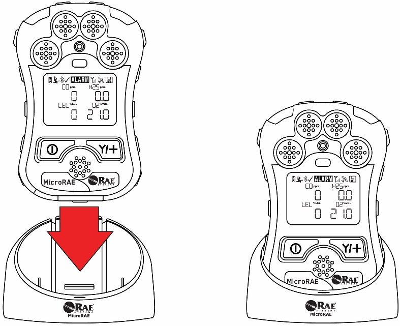
MicroRAE User’s Guide

                                      WARNINGS
This Manual must be carefully read by all individuals who have or will have the responsibility of
using, maintaining, or servicing this product. The product will perform as designed only if it is
used, maintained, and serviced in accordance with the manufacturer’s instructions. The user
should understand how to set the correct parameters and interpret the obtained results.

                                         CAUTION!
    •   Only use the RAE Systems rechargeable lithium-ion battery pack supplied with the
        instrument.
    •   Charge the instrument Li-ion battery using the specifically supplied RAE Systems charger
        and only outside hazardous areas. The maximum voltage from the charger must not
        exceed 6.0 VDC.
    •   Any data download device connected to this instrument must be approved SELV or Class
        2 equipment.
    •   Use of non-RAE Systems components will void the warranty and can compromise the
        safe performance of this product.
    •   Warning: Substitution of components may impair safe performance of this product.

SPECIAL CONDITIONS FOR SAFE USE
    •   This multi-gas monitor must be calibrated if it does not pass a bump test, when a new
        sensor has been installed, or at least once every 180 days, depending on use and sensor
        exposure to poisons and contaminants
    •   No precautions against electrostatic discharge are necessary for portable equipment that
        has an enclosure made of plastic, metal or a combination of the two, except where a
        significant static-generating mechanism has been identified. Activities such as placing
        the item on a belt, operating a keypad or cleaning with a damp cloth, do not present a
        significant electrostatic risk. However, where a static-generating mechanism is identified,
        such as repeated brushing against clothing, then suitable precautions shall be taken,
        e.g., the use of anti-static footwear.

Note: Users are recommended to refer to ISA -RP12.13, Part II-1987 for general information on
installation, operation, and maintenance of combustible gas detection instruments.

                                                 5
MicroRAE User’s Guide
                             WARNINGS
ONLY THE COMBUSTIBLE GAS DETECTION PORTION OF THIS INSTRUMENT HAS BEEN
ASSESSED FOR PERFORMANCE.

UNIQUMENT, LA PORTION POUR DÉTECTOR LES GAZ COMBUSTIBLES DE CET
INSTRUMENT A ÉTÉ ÉVALUÉE.

CAUTION: BEFORE EACH DAY’S USAGE, SENSITIVITY OF THE COMBUSTIBLE GAS
SENSOR MUST BE TESTED ON A KNOWN CONCENTRATION OF METHANE GAS
EQUIVALENT TO 20 TO 50% OF FULL-SCALE CONCENTRATION. ACCURACY MUST BE
WITHIN 0 AND +20% OF ACTUAL. ACCURACY MAY BE CORRECTED BY CALIBRATION
PROCEDURE.

ATTENTION: AVANT CHAQUE UTILISATION JOURNALIERE VERIFIER LA SENSIBILITE
AVEC UNE CONCENTRATION CONNUE DE METHANE EQUIVALENTE A 20-50% DE LA
PLEINE ECHELLE. LA PRECISION DOIT ETRE COMPRISE ENTRE 0-20% DE LA VALEUR
VRAIE ET PEUT ETRE CORRIGEE PARUNE PROCEDURE D’ETALONNAGE.

CAUTION: HIGH OFF-SCALE READINGS MAY INDICATE AN EXPLOSIVE
CONCENTRATION.

ATTENTION: DES LECTURES SUPÉRIEURES A L’ÉCHELLE PEUVENT INDIQUER DES
CONCENTRATIONS EXPLOSIVES.

                                    6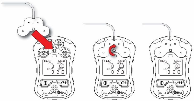
MicroRAE User’s Guide
This device complies with part 15 of the FCC Rules. Operation is subject to the following two
conditions: (1) This device may not cause harmful interference, and (2) this device must accept
any interference received, including interference that may cause undesired operation.

Warning: Changes or modifications to this unit not expressly approved by the party responsible
for compliance could void the user's authority to operate the equipment.

Note: This equipment has been tested and found to comply with the limits for a Class B digital
device, pursuant to part 15 of the FCC Rules. These limits are designed to provide reasonable
protection against harmful interference in a residential installation. This equipment generates,
uses and can radiate radio frequency energy and, if not installed and used in accordance with the
instructions, may cause harmful interference to radio communications. However, there is no
guarantee that interference will not occur in a particular installation. If this equipment does cause
harmful interference to radio or television reception, which can be determined by turning the
equipment off and on, the user is encouraged to try to correct the interference by one or more of
the following measures:

    •   Reorient or relocate the receiving antenna.
    •   Increase the separation between the equipment and receiver.
    •   Connect the equipment into an outlet on a circuit different from that
        to which the receiver is connected.
    •   Consult the dealer or an experienced radio/TV technician for help.

This device contains license-exempt transmitter(s)/receiver(s) that comply with Innovation,
Science and Economic Development Canada’s license-exempt RSS(s). Operation is subject to
the following two conditions:

(1) This device may not cause interference.
(2) This device must accept any interference, including interference that may cause undesired
operation of the device.

L’émetteur/récepteur exempt de licence contenu dans le présent appareil est conforme aux CNR
d’Innovation, Sciences et Développement économique Canada applicables aux appareils radio
exempts de licence. L’exploitation est autorisée aux deux conditions suivantes:
1) L’appareil ne doit pas produire de brouillage;
2) L’appareil doit accepter tout brouillage radioélectrique subi, même si le brouillage est
susceptible d’en compromettre le fonctionnement.

                                                  7
MicroRAE User’s Guide
Product Marking
The MicroRAE (PGM-26XX) is certified according to the IECEx scheme, ATEX and CSA for US
and Canada under the intrinsic safety method of protection.

The PGM-26XX is marked with the following information:
RAE SYSTEMS
1349 Moffett Park Dr.
Sunnyvale, CA 94089 USA
Type PGM-26XX
Serial No/barcode: XXXX-XXXX-XX

 IECEx SIR
                             2460
 15.0039X
                       SIRA 15 ATEX 2080X
 Ex ia d IIC T4 Gb                                       Cl. I Dv. 1, Grps A, B, C, D T-Code T4.
                          II 2G Ex ia d IIC T4 Gb
 Ex ia I Ma                                              C22.2 No.152-M1984
                           I M1 EX ia I Ma
                                                         ANSI/ISA-12.13.01-2000
                                                         Intrinsically safe/Sécurité intrinséque
-20º C < Tamb < +60º C
Um: 6V
Battery pack: M03-3004-000

Warning: Substitution of components may impact intrinsic safety.
Avertissement: La substitution de composants peut compromettre la securité intrinsèque.

WARNING: Read and understand instruction manual before operation or servicing.
AVERTISSEMENT: Lisez et comprenez le manual d’instructions avant d’utiliser ou service.
WARNING: Substitution of components may impact intrinsic safety.
AVERTISSEMENT: La substitution de composants peut compromettre la sécurité intrinsèque.
WARNING: To prevent ignition of a hazardous atmosphere, batteries must only be charged in an
area known to be non-hazardous. Um = 6.0V. Use only approved charger.
AVERTISSEMENT: Afin de prevenir l’inflammation d’atmosphères dangereuse, ne charger le jeu
de batteries que dans des emplacement designés non dangereux. Um = 6V Utilisez uniquement
un chargeur approuvé.

Only use approved battery pack: M03-3004-000.

Only charge the battery in safe area in the ambient temperature range 0°C ≤ Tamb ≤ 40°C.

Note: Some wireless approvals have limited validity periods. Please contact Honeywell to make
sure they are valid.

UAE Wireless Approval Marking

                     TRA                                             TRA
        Model: PGM-2600                                  Model: PGM-2601
   Authorization No: ER46920/16                     Authorization No: ER46780/16
      Dealer No: DA39257/15                            Dealer No: DA39257/15

                                               8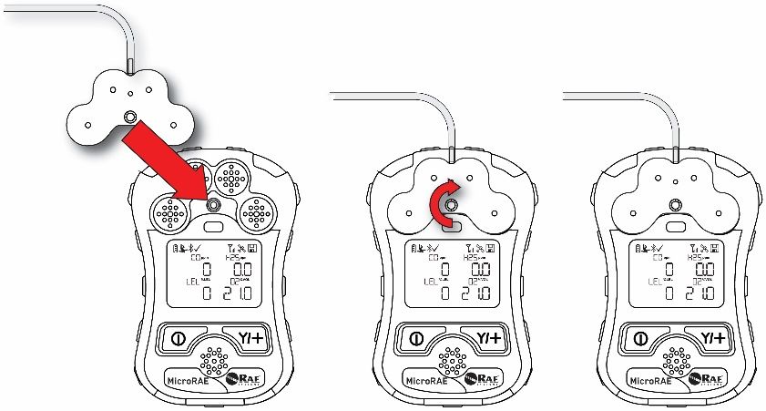
MicroRAE User’s Guide

Proper Product Disposal At End Of Life
              EU Directive 2012/19/EU: Waste Electrical and Electronic Equipment (WEEE)
              This symbol indicates that the product must not be disposed of as general
              industrial or domestic waste. This product should be disposed of through suitable
              WEEE disposal facilities. For more information about disposal of this product,
              contact your local authority, distributor, or the manufacturer.

Sensor Specifications, Cross-Sensitivities, And Calibration Information
For information on sensor specifications, cross-sensitivities, and calibration information, refer to
RAE Systems Technical Note TN-114: Sensor Specifications And Cross-Sensitivities (available
for free download from www.raesystems.com). All specifications presented in this Technical Note
reflect the performance of standalone sensors. Actual sensor characteristics may differ when the
sensor is installed in different instruments. As sensor performance may change over time,
specifications provided are for brand-new sensors.

Make Sure Firmware Is Up To Date
For best operation, make sure your monitor is running the latest firmware. Check
www.raesystems.com for updates.

                                                 9
MicroRAE User’s Guide
1. Standard Contents
The MicroRAE is available in various user-specified configurations, each with the accessories
shown below.

In addition to the instrument, the following are included:

      Item                                                                  Part Number
      Travel charger                                                        M03-3005-000
      AC adapter                                                            500-0036-102
      USB cable                                                             410-0203-000
      QuickStart guide                                                      M03-4002-000
      Calibration cap for diffusion models                                  M03-3003-000
      Warranty card                                                         000-4008-001

                                                 10
MicroRAE User’s Guide
2. General Information
The MicroRAE gas monitor combines continuous monitoring capabilities for toxic and combustible
gases with Man Down Alarm functionality, BLE (Bluetooth Low Energy), and optional GPS and
either Wi-Fi, Mesh Radio, or NB-IoT wireless connectivity in a compact, portable instrument. It
offers a selection of field-replaceable electrochemical and combustible sensors to fit a wide
variety of applications. Its wireless capability elevates protection by providing real-time access to
instrument readings and alarm status from any location for better visibility and faster response.
2.1. Key Features
• All-in-one continuous monitoring capabilities for oxygen, toxic and combustible gases, for a
total of up to four threats at a time
• Wireless access to real-time instrument readings and alarm status from any location
• Local and remote wireless notification of alarm conditions, including Man Down Alarm and
location
• GPS functionality to allow better location
• Simple maintenance with easily accessible sensors
• Glance Mode gives quick overview of sensors and wireless configuration
LED
LED
Gas inlets
Light
Sensor
Alligator
Clip
(on back) Display
MODE
Key
Y/+
Key
Alarm
Buzzer
LED
LED
Charging and
Communication
Contacts
(on bottom)
11MicroRAE User’s Guide
3. User Interface
The MicroRAE’s user interface consists of the display, LEDs, an alarm buzzer, and two keys.
3.1. Display Overview
The LCD display provides visual feedback that includes the sensor types, readings, battery
condition, and other functions.
Calibration and bump test
BLE on up to date
Instrument in alarm
Man Down alarm on Integrated Radio on and signal strength
GPS on and signal strength
Battery Status
Datalog Status indicator
Sensor type Reading value
Unit of measure
3.1.1. Status Indicator Icons
Along the top of most screens are status indicators that tell you whether a function is operating
and/or its strength or level.
Icon Function
Mesh, Wi-Fi, or NB-IoT enabled and power on
Mesh Radio, Wi-Fi Wireless, or NB-IoT status: the radio is off
(replaced by “R” when Roaming is on).
Mesh Radio or Wi-Fi Wireless status: the radio is on (replaced
by “R” when Roaming is on). Wireless strength is indicated by
0 to 4 bars. Flashing icon without bars indicates network has
not been found.
Cannot find network (blinking icon)
For Mesh Radio & Wi-Fi, signal is less than 20%
For NB-IoT, signal strength is -96dBm to -105dBm
For Mesh Radio & Wi-Fi, signal is 21% to 50%
For NB-IoT, signal strength is -86dBm to -95dBm
For Mesh Radio & Wi-Fi, signal is 51% to 70%
For NB-IoT, signal strength is -76dBm to -85dBm
For Mesh Radio & Wi-Fi signal 71% to 100%
For NB-IoT, Signal strength is greater than -75dBm
Roaming status: “R” blinks when trying to find a network
(replaced by antenna when Roaming is off). “R” is solid when
network communication established.
Network joined, signal very low RSSI (0% to 19%)
Network joined, signal low RSSI (20% to 49%)
12MicroRAE User’s Guide
Icon Function
Network joined, signal medium RSSI (50% to 69%)
Network joined, signal good RSSI (70% to 100%)
No radio icon: The instrument is not equipped with a radio
module.
BLE (Bluetooth Low Energy)
If installed but disconnected, the icon blinks 1 time per second.
If connected with another device, the icon is shown and does
not blink.
GPS Status: off, no satellites found, 1 to 3 satellites, 4 to 8
satellites, 9 to 12 satellites.
Datalogging status (shown when datalogging is on, blank when
off).
Battery voltage is greater than 70%
Battery voltage is 41% to 70%
Battery voltage is 11% to 40%
Battery voltage is less than 10% (icon blinks)
Calibration overdue.
Bump test overdue.
Man Down alarm enabled.
All sensors tested and calibrated tick mark (all sensors have
been bump tested and calibrated; no sensor is overdue for a
bump test or calibration according to the intervals configured
on the instrument.
Go to next page.
Instrument is in alarm (flashes)
13MicroRAE User’s Guide
3.1.2. Keys & Interface
The MicroRAE has two keys:
MODE Y/+
In addition to their labeled functions, the keys labeled [MODE] and [Y/+] act as “soft keys” that
control different parameters and make different selections within the instrument’s menus. From
menu to menu, each key controls a different parameter or makes a different selection.
In addition to the functions described above, either key can be used to manually activate display
backlighting. Press a key when the backlighting is off to turn it on.
3.2. Screen Display For Various Numbers Of Active Sensors
The MicroRAE can accommodate from one to four sensors. When one or more sensors is either
not installed or turned off, the display only shows the installed, active sensors:
14MicroRAE User’s Guide
3.3. Menus
The reading menus are easy to step through by pressing the [MODE] and [Y/+] key.
*
* If the MicroRAE is Wi-Fi equipped: Wi-Fi-equipped instruments can receive up to five
messages. If a message has been received by the MicroRAE, the number of messages is
displayed (1 MSG, etc.). The display shows the message sequentially, cycling through the
message each half-second. The Message number, “page” of the message (it automatically
breaks a message across screens), and received time and date are shown. Up to five messages
can be received by the MicroRAE. Pressing [MODE] steps through the messages. When “Exit” is
shown, press [Y/+] to return to the Main Display.
NB-IoT only: IP address and RSSI (received signal strength) are shown. The RSSI value is a
negative number (-93dBm).
Note: In most cases, if no buttons are pressed at any of the menu steps for 60 seconds, the
instrument reverts to the main display.
15MicroRAE User’s Guide
3.4. Glance Mode
If you want to check your instrument’s configuration and it is turned off, you do not have to turn it
on. Press and hold [Y/+] until the screen illuminates and shows the configuration. This tells you
the installed sensors:
Press [Y/+] to advance through screens that tell you if the radio is on, BLE is on, GPS is on, Wi-Fi
is on, NB-IoT is on, etc. These change, depending on the instrument’s configuration.
To exit, press [MODE], and the display shuts off.
Note: If you do not press a button for 60 seconds, it turns off automatically.
3.5. Panic Alarm
Press and hold [Y/+] at any time to trigger the Panic Alarm. The display shows “PANIC ALARM”
and sends a message to the Location Manager or ProRAE Guardian.
(Note: Use ProRAE Studio II to define information and its prioritization for viewing.)
In addition, the instrument alarms (audible and visible) four times per second. The instrument also
sends an emergency message to the Location Manager or ProRAE Guardian.
Press [Y/+] to clear the alarm. The alarm stops and the display returns to the main reading
screen.
3.6. Confidence LED
You can use ProRAE Studio II to program the MicroRAE to continually provide an LED blink
every 3 seconds so that you can tell without looking closely that the instrument is working.
16MicroRAE User’s Guide
4. Mesh Wireless Control And Submenus
When you step through the main menu, as shown in the Menus diagram, there are four screens
for wireless communication, containing information on wireless settings and status. If Roaming is
not turned on, then you must set a PAN ID in order to communicate with a Mesh Network.
Note: These are only present if the MicroRAE is equipped with a Mesh Network wireless module.
17MicroRAE User’s Guide
5. Battery Charging
Always fully charge the battery before using the MicroRAE. Its Li-ion battery is charged by placing
the MicroRAE in its Travel Charger (P/N: M03-3005-000) or Charging Cradle. Contacts on the
bottom of the instrument meet the Travel Charger’s or Charging Cradle’s contact pins,
transferring power.
Note: Before attaching the MicroRAE to a charger, visually inspect the contacts to make sure
they are clean. If they are not, wipe them with a soft, dry cloth. Do not use solvents or cleaners.
WARNING
To reduce the risk of ignition of hazardous atmospheres, recharge, remove or replace the
battery only in an area known to be non-hazardous!
Align the Travel Charger with the middle of the MicroRAE, squeeze the latches on both
sides of the Travel charger, and press it until it is firmly attached to the MicroRAE.
Then release the latches. Make sure you press the latches close to the instrument
instead of at their ends.
TO AVOID DAMAGE, DO NOT ATTACH OR REMOVE THE TRAVEL CHARGER
WITHOUT SQUEEZING THE LATCHES!
Next, put the plug from the power supply (P/N: 500-0036-102) into the jack on the side of the
Travel Charger.
Plug the other end of the charger into a power source (AC outlet or mobile power port in a
vehicle, depending on the model). When power is applied and the MicroRAE’s battery is
charging, the LED glows red. The LED glows green when the battery is fully charged.
Note: For mobile charging, only use Automotive Charging Adapter (P/N 003-3004-000) from RAE
Systems by Honeywell.
To remove the MicroRAE from the Travel Charger, squeeze the latches on the sides of the Travel
Charger and pull it away from the instrument. Always press near the top of the latches, not the ends.
18MicroRAE User’s Guide
5.1. Charger Station (Multi-Charger)
A Multi Charger (P/N: M03-0300-000) is available for charging up to five MicroRAE instruments at
one time. Note: It uses a different AC adapter (P/N: 500-0156-000) than the travel charger.
Note: The Charger Station is not available in Brazil.
Insert the plug from the power supply into the jack on the side of the Multi Charger:
Plug the other end of the charger into a power source.
5.1.1 Charging With The Multi Charger
Press the MicroRAE into any of the Multi Charger’s cradles. It should be held firmly in place. If the
power is connected to the Multi Charger, the LED indicator on the cradle should glow. When
power is applied and the MicroRAE’s battery is charging, the LED glows red. The LED glows
green when the battery is fully charged.
19MicroRAE User’s Guide
Remove the instrument from the cradle by tilting the release on the rear of the charging cradle
away from the instrument and lifting the MicroRAE.
20MicroRAE User’s Guide
5.2. Battery States
The battery icon on the display shows how much charge is in the battery and alerts you to any
charging problems.
Battery low 1/3 charge 2/3 charge Full charge
When the battery’s charge falls below a preset voltage, the instrument warns you by beeping
once and flashing once every minute. The instrument automatically powers down within 10
minutes, after which you will to recharge the battery.
6. External Filter
The External Filter (M03-3009-000) is designed to prevent debris from entering the MicroRAE in
dirty or dusty environments. Align the filter over the sensor openings and tighten the Philips screw
to secure it in place. Replace the filter when it appears dirty.
21MicroRAE User’s Guide
7. Turning The MicroRAE On And Off
7.1. Turning The MicroRAE On
With the instrument turned off, press and hold the [MODE] key until the audible alarm stops, and
then release.
When starting up, the MicroRAE turns the backlight on and off, beeps once, blinks once, and
vibrates once. “Honeywell” should appear first. During a normal startup, this is followed by a
progression of screens that tell you the MicroRAE’s current settings.
Then the MicroRAE’s main reading screen appears. It takes 45 seconds for some sensors to
show a reading, so if any have not warmed up by the time the main screen is shown, you will see
“- -” instead of a numerical value until the sensor provides data (if you turn a sensor off and on
again, it also shows “- -” for up to 45 seconds). Then it displays instantaneous readings similar to
the following screen (depending on the sensors installed) and is ready for use.
Note: If the battery is completely empty, the MicroRAE shuts off. You should charge the before
turning it on again.
IMPORTANT!
If a major error that prevents the MicroRAE from functioning is found during startup, the message
“Contact Service” is shown on the display. The instrument should be shut off and serviced.
7.2. Turning The MicroRAE Off
Press and hold [MODE]. A 5-second countdown to shutoff begins. You must hold your finger on
the key for the entire shutoff process until the MicroRAE is powered off.
Caution: The alarm is very loud. During startup, you can mute most of the sound by holding a
finger over the alarm port. Do not put tape over the alarm port to permanently mute it.
22MicroRAE User’s Guide
7.3. Testing Alarm Indicators
Under normal-operation mode and non-alarm conditions, the buzzer, vibration alarm, LED, and
backlight can be tested at any time by pressing [Y/+] once.
IMPORTANT!
If any alarm does not respond, check MicroRAE’s alarm settings to make sure all alarms are
enabled (selected setting under Programming/Alarms/Alarm Settings should be “All Enabled”). If
any alarms are enabled but not functional, the instrument should not be used.
7.4. Glance Mode
Glance Mode allows you to get vital information without turning the MicroRAE on. You can check
information such as the instrument’s model number, installed sensor types, etc., which may help
when taking inventory of instruments and their sensors or when working with service or support
personnel. Glance Mode can be enabled/disabled via ProRAE Studio II.
7.4.1 Enter Glance Mode
Note: The instrument must be configured so that Glance Mode is turned on (the default mode is
“On”). This can be done in ProRAE Studio II.
With the MicroRAE turned off, press and hold [Y/+] to enter Glance Mode. The feature is latched,
meaning that it runs even after you release the [Y/+] key. If you see the message “GLANCE
DISABLED,” you must configure the instrument to use Glance Mode.
If Glance Mode is enabled, the first screen is displayed. After releasing [Y/+], other screens
release, other screens can be displayed by pressing the [Y/+] Key. In ProRAE Studio II, Glance
Mode can be enabled or disabled by checking or unchecking the box labeled “Enable Glance
Mode.”
23MicroRAE User’s Guide
7.4.2 Screens
Every screen displayed in sequence as configuration. Press [Y/+] to advance to the next screen.
Press [MODE] to exit Glance Mode and turn the instrument off. The screens are shown in
sequence.
7.4.3 Exit Glance Mode
MicroRAE exits Glance Mode and turns off when you press the [MODE] key. In addition, if you
do not press either key in 60 seconds, the MicroRAE automatically exits Glance Mode.
7.5. Comfort Beep
A Comfort Beep is a single beep of the audible alarm at 60-second intervals that provides a
reminder that the MicroRAE that it is functioning. It can be turned on or off.
7.6. Man Down Alarm
The Man Down Alarm is a critical and potentially lifesaving safety feature of every MicroRAE. The
Man Down Alarm is based on the premise that if the instrument is motionless when it is not
supposed to be, something wrong may be happening to its user. If that is the case, the MicroRAE
not only goes into alarm locally on the instrument, but also remotely, over a wireless network, to
notify people in the vicinity, as well as remote safety officers at a command center, that a person
is down, so that help can be dispatched quickly.
Note: Remote notification requires wireless connection to a network.
Whenever the Man Down feature is on, the main screen displays a Man Down icon along the top
to indicate it is active:
IMPORTANT!
When gas alarm conditions exist at the same time as the Man Down alarm is activated, the pre-alarm
stage is skipped, and the instrument goes straight into Super Alarm (gas and Man Down) with four
beeps/flashes per second.
When the Man Down feature is on and there is no gas alarm, the MicroRAE senses that it is
motionless for the amount of time set in the “Motionless Time” parameter via ProRAE Studio II. If the
instrument is not moved during that time, then a pre-alarm is activated to alert the user, and shows the “OK?”
screen. Pressing [Y/+] clears the alarm and returns the MicroRAE to its normal operation. Pressing [MODE]
sets it into Man Down Alarm (and if wireless connectivity is enabled, a Man Down message is sent in real time
to remote observers). If neither key is pressed, then after the countdown, it goes into Man Down Alarm (again
sending a message to remote observers if wirelessly enabled).
Settings for Man Down are available in ProRAE Studio II for:
• Off/On
• Motion Sensitivity (set to low, medium, high, or custom percentage)
• Falldown Sensitivity (set to low, medium, or high to compensate for ambient vibration or motion)
• Window (time the instrument is motionless before initiating a pre-alarm, in seconds)
• Warning Time (countdown, in seconds, from pre-alarm to Man Down alarm)
• Falldown Window (time after falling down is sensed, in seconds); Whenever the acceleration
speed is greater than the Falldown Sensitivity, the Man Down feature is invoked.
24MicroRAE User’s Guide
When the Man Down alarm is activated, the buzzer sounds and LEDs flash continuously, and a countdown
begins.
• If the MicroRAE’s user presses [Y/+] for “Yes” in response to the “OK?” question on the screen
before the countdown reaches zero, the Man Down alarm stops and the main reading screen is
displayed.
• If the person does not press [Y/+] for “Yes” in response to the “OK?” question on the screen
before the countdown reaches zero, the Man Down alarm is sounded and LEDs flash
continuously.
• If the person presses [MODE] during the countdown, answering the “OK?” question by pressing
[MODE] for “No,” the Man Down alarm starts.
If wireless connectivity is enabled, and the MicroRAE is connected to a network, a Man Down message is
also sent to remote observers.
IMPORTANT!
When using the Travel Charger or Truck Mount to charge a MicroRAE, the Man Down alarm is
automatically disabled so that the instrument does not go into Man Down alarm because of inactivity. This
requires no changes to the instrument’s settings.
Please note that Travel Chargers with a serial number lower than M0320001U5 and Truck Mounts with
serial numbers lower than M035000170 do not support this feature. It is also recommended that older
MicroRAE instruments have their firmware upgraded to version 1.10 or higher.
7.6.1 Parameter Settings And Sequence Of Events
When a fall is sensed, as determined by the Motion Sensitivity and Falldown Sensitivity settings,
the Falldown Window starts. If motion resumes, then the instrument resets itself and is ready for
the next fall or motionless period.
7.6.1.1. Parameters Configured By ProRAE Studio II
Index Parameter Default Value Range
1 Window time 30 seconds 30 to 90 seconds
2 Warning time 30 seconds 30 to 180 seconds
3 Falldown Window time 180 seconds 0* to approximately 1,000 seconds
4 Motion Sensitivity Medium Low (7%)
Medium (37%),
High (63%),
Custom
5 Fall Sensitivity Medium Low (33%),
Medium (67%),
High (100%),
Custom
* If the Falldown Window value is set to “0,” the Man Down algorithm focuses only on motionless
behavior. If the Falldown Window value is not set to zero, the algorithm uses acceleration to
trigger its function.
If acceleration is sensed, and motion does not resume, then the Warning Time starts. During this
period, the instrument waits for motion. If no motion occurs by the end of the Warning Time, the
Window period is entered. During that time, the display shows the “Are You OK?” message. The
buzzer sounds and LEDs flash continuously, and a countdown begins.
• If the MicroRAE’s user presses [Y/+] for “Yes” in response to the “Are You OK?” question on
the screen before the countdown reaches zero, the Man Down alarm stops and the main
reading screen is displayed.
25MicroRAE User’s Guide
• If the person does not press [Y/+] for “Yes” in response to the “Are You OK?” question on the
screen before the countdown reaches zero, the Man Down alarm is sounded and LEDs flash
continuously.
• If the person presses [MODE] for “No” during the countdown, the Man Down alarm starts.
If wireless connectivity is enabled, and the MicroRAE is connected to a network, a Man Down message is
also sent to remote observers.
7.6.1.2. Turn Man Down On Or Off
Turn on the Man Down feature, or turn it off, using ProRAE Studio II.
7.6.1.3. Set The Sensitivity
Individual sensitivity settings for Motion (acceleration) and Falldown allow for customization to
individuals or activities. Default values are set at the factory, but it can be helpful to try other
settings in order to customize an instrument’s response.
7.6.1.4. Set The Times
Once a trigger occurs, there is a time before a warning is displayed and when the Man Down
alarm is initiated.
7.6.1.5. Upload Settings To The MicroRAE
When any changes to Man Down (or any other) settings are made in ProRAE Studio II, you must
upload them to the instrument in order for them to be used. Click the “Upload all settings” button.
26MicroRAE User’s Guide
7.7. Calibration Status
If any sensor requires calibration, then “Calibration Overdue” icon is shown by the sensor name in
the display:
Calibration is required if:
• The sensor module has been replaced with one whose calibration is overdue.
• The defined period of time between calibrations has been exceeded, according to the
policy set for the instrument.
• If you have changed the calibration gas type without recalibrating the instrument.
• The sensor has failed a previous calibration.
7.8. Bump Status
If any sensor requires a bump test, then “Bump Overdue” icon is shown by the sensor name in
the display:
A bump test is required if the defined period of time between bump tests has been exceeded.
This interval is set by an administrator using ProRAE Studio II.
27MicroRAE User’s Guide
8. Modes Of Operation
The MicroRAE has two user modes, selectable through ProRAE Studio II.
8.1. Basic User Mode
In Basic User Mode, some restrictions are applied, including password protection that guards
against entering Programming Mode by unauthorized personnel.
8.2. Advanced User Mode
In Advanced User Mode, there are no access restrictions (you do not need a password), and the
MicroRAE provides the indications and data you need most for typical monitoring applications.
9. Programming
The menu in Programming Mode is to adjust many of the MicroRAE’s settings, calibrate sensors,
and initiate communication with a computer. It has the following submenus:
• Calibration
• Sensor On/Off
• Clear Datalog
• Monitor Setup
• Set Radio (Wireless)
Note: Some settings are only visible and can only be changed in ProRAE Studio II. This requires
connecting the instrument to a computer running ProRAE Studio II and having administrative
privileges. For a list of which parameters can be set in Programming Mode on the MicroRAE, in
ProRAE Studio II, or both, refer to “Editing Features” on page 67.
9.1. Enter Programming In Basic Mode
1. To enter Programming Mode, press and hold [MODE] and [Y/+] until you see the Password
screen.
2. Input the 4-digit password:
• Increase the number from 0 through 9 by pressing [Y/+].
• Step from digit to digit using [MODE].
• After inputting the password’s four digits, advance to “?”
• Press [Y/+] to register the password and enter Programming Mode. If you receive the
message “PASS ERR RETRY?” press [Y/+] to re-enter the password. Otherwise, press
[MODE] to return to the main screen.
If you make a mistake, you can cycle through the digits by pressing [MODE] and then using [Y/+]
to change the number in each position.
Note: The default password is 0000.
Note: The password screen only appears when you enter the Programming Mode the first time
after turning the instrument on in Basic Mode. If you have input the correct password, you do not
have to input it again to enter Programming Mode until you turn the instrument off and on again.
28MicroRAE User’s Guide
Once you enter Programming Mode, the Calibration screen is shown. Press [MODE] to step
through the programming screens.
9.2. Enter Programming In Advanced Mode
To enter Programming Mode, press and hold [MODE] and [Y/+] until you see the Calibration
screen. No password is necessary in Advanced Mode. Note: Some parameters can only be
viewed or changed in ProRAE Studio II.
9.3. Menus And Submenus
In Programming Mode, menus and submenus are organized as shown here:
Calibration Sensor On/Off Clear Datalog Monitor Setup Set Radio
Single Bump Sensor 1 On/Off GPS On/Off* BLE On/Off
Single Zero Sensor 2 On/Off Set Site ID NB-IoT On/Off*****
Single Span Sensor 3 On/Off Set User ID Wi-Fi On/Off**
Multi Bump Sensor 4 On/Off Sent History**
Fresh Air Cal Mesh Roaming Enable***
Multi Span Radio On/Off***
Exit Set PAN ID****
Set Channel****
Join Network****
Factory Reset****
Exit
* GPS-equipped version only. **** Only available if Roaming is turned off.
** Wi-Fi-equipped version only. ***** NB-IoT-equipped version only.
*** Mesh Wirelessly equipped version only.
29MicroRAE User’s Guide
9.3.1. Calibration
Use this menu to perform zero or span calibration for one or more sensors, and change the gas
concentration value assumed to be used in span calibration, as well as zero calibration and
calibration reference gas. Refer to “Calibration And Testing” on page 41 for guidance on setting
up the instrument for calibration.
9.3.1.1. Single Bump
You can perform a separate bump test on each individual sensor.
The active sensors’ names are shown in a list. Press [MODE] to highlight the sensor you want to
bump test, and then press [Y/+] to select it.
When the Apply Gas screen is shown, connect the calibration gas to the instrument, and start the
bump test by pressing [Y/+]. If you do not want to perform a single bump test, press [MODE] to
quit.
Note: You can abort a bump test by pressing [MODE] once testing has started.
When the Multi Bump test is done, a screen is shown, with the sensor names and either “Pass” or
“Fail” shown next to them.
9.3.1.2. Single Zero
This allows you to perform zero (fresh air) calibration on individual sensors. For most
applications, the instrument should be zero calibrated in clean ambient air with 20.9% oxygen
(02). For more precise low 02 percentage accuracy, and after a new 02 sensor is put into the
instrument, zeroing should be performed with nitrogen (N2). A zero calibration should precede a
span calibration.
The active sensors’ names are shown in a list. Press [MODE] to highlight the sensor you want to
zero calibrate, and then press [Y/+] to select it.
When the Zero Calibration screen is shown with the sensor name and its measurement unit, start
the zero calibration by pressing [Y/+]. If you do not want to perform a calibration, press [MODE] to
quit.
Note: You can abort a zero calibration by pressing [MODE] once testing has started.
When the zero calibration is done, the Calibration Results screen is shown with either “Pass” or
“Fail” shown.
9.3.1.3. Single Span
Instead of performing a span calibration on more than one sensor simultaneously, you can select a
single sensor and perform a span calibration.
The active sensors’ names are shown in a list. Press [MODE] to highlight the sensor you want to
span calibrate, and then press [Y/+] to select it.
When the Apply Gas screen is shown with the sensor name and its measurement unit, connect a
cylinder of span gas, start its flow, and then start the span calibration by pressing [Y/+]. If you do
not want to perform a span calibration, press [MODE] to quit.
Note: You can abort a span calibration by pressing [MODE] once testing has started.
When the span calibration is done, the Calibration Results screen is shown with either “Pass” or
“Fail” shown.
30MicroRAE User’s Guide
9.3.1.4. Multi Bump
Depending on the configuration of your MicroRAE and the span gas you have, you can perform a
bump test simultaneously on multiple sensors.
The selected sensors and their values are shown on the screen. With calibration gas connected
to the instrument, start a multiple bump test by pressing [Y/+]. If you do not want to perform a
multiple bump test, press [MODE].
Note: You can abort a multiple bump test by pressing [MODE] once testing has started.
When the Multi Bump test is done, a screen is shown, with the sensor names and either “Pass” or
“Fail” shown next to them.
9.3.1.5. Fresh Air Calibration
You can perform a fresh air calibration simultaneously on multiple sensors. This procedure
determines the zero point of the sensor calibration curve for all the sensors that require a zero
calibration. The instrument should be zero calibrated in clean ambient air with 20.9% oxygen. A
fresh air calibration should precede a span calibration.
The selected sensors are shown on the screen. Start a multiple zero test by pressing [Y/+]. If you
do not want to perform a test, press [MODE].
Note: You can abort a multiple zero test by pressing [MODE] once testing has started.
When the Multi Zero test is done, a screen labeled Calibration Results is shown, with the sensor
names and either “Pass” or “Fail” shown next to them.
9.3.1.6. Multi Span
Depending on the configuration of your MicroRAE and the span gas you have, you can perform a
span calibration simultaneously on multiple sensors.
The selected sensors and their values are shown on the screen. With calibration gas connected
to the instrument and turned on, start a multiple span calibration by pressing [Y/+]. If you do not
want to perform a multiple span calibration, press [MODE].
Note: You can abort a multiple span calibration by pressing [MODE] once testing has started.
When the Multi Span calibration is done, a screen labeled Calibration Results is shown, with the
sensor names and either “Pass” or “Fail” shown next to them.
9.3.1.7. Exit
Exit to “Sensor On/Off”: Press [Y/+].
Return to the top item in the Calibration menu, “Single Bump”. Press [MODE].
9.3.2. Sensor On/Off
You can turn sensors on or off via this set of submenus. The word “ON” or “OFF” below each
sensor’s name tells you its status.
1. Press [MODE] to advance through the sensors.
2. Press [Y/+] to turn a selected sensor on or off.
3. Press [MODE] until “?” is selected.
4. Press [Y/+] to save your selection and exit to “Clear Datalog”. Otherwise, to return to the
first sensor, press [MODE].
31You can also read