Operating Cisco HyperFlex HX Data Platform Stretch Clusters
←
→
Page content transcription
If your browser does not render page correctly, please read the page content below

White Paper

Operating Cisco HyperFlex HX Data
Platform Stretch Clusters

Version 2.0 rev2
November 2020

Document information
  Document summary                                                              Prepared for                    Prepared by
 V2.0 rev2 Stretch Cluster information for HX 3.5, and 4.0                      Cisco Field                     Aaron Kapacinskas

Intended use and audience
This document contains confidential material that is proprietary to Cisco. The materials, ideas, and concepts contained herein are
to be used exclusively to assist in the configuration of Cisco® software solutions.

Legal notices
All information in this document is provided in confidence and shall not be published or disclosed, wholly or in part, to any other
party without Cisco’s written permission.

© 2020 Cisco and/or its affiliates. All rights reserved. This document is Cisco Public Information.                           Page 1 of 47
White Paper

Contents
Document information .................................................................................................................................................................................................. 1
Intended use and audience ......................................................................................................................................................................................... 1
Legal notices .................................................................................................................................................................................................................. 1
Prerequisites .................................................................................................................................................................................................................. 4
Introduction .................................................................................................................................................................................................................... 4
Cisco HyperFlex HX Data Platform general overview: Components and environment ................................................................................... 4
     Cisco Unified Computing System ......................................................................................................................................................................... 4
     Fabric interconnect traffic and architecture ........................................................................................................................................................ 5
Cisco HyperFlex HX Stretch Clusters ........................................................................................................................................................................ 9
     What is a Stretch Cluster ....................................................................................................................................................................................... 9
     Business need for a stretch cluster .................................................................................................................................................................... 10
     Stretch cluster physical limitations ..................................................................................................................................................................... 10
     Solution components ............................................................................................................................................................................................ 10
Stretch cluster architecture ....................................................................................................................................................................................... 13
     Limitations ............................................................................................................................................................................................................... 14
     About Zones ........................................................................................................................................................................................................... 15
     Hardware Matching ............................................................................................................................................................................................... 16
     Overlay Networks .................................................................................................................................................................................................. 16
     Fabric interconnects .............................................................................................................................................................................................. 17
     Fabric Interconnects Uplink Best Practices ...................................................................................................................................................... 18
     VMware vCenter .................................................................................................................................................................................................... 19
     VMware vCenter HA Settings .............................................................................................................................................................................. 20
     Witness configuration ........................................................................................................................................................................................... 23
     I/O path in a stretch cluster ................................................................................................................................................................................. 24
     Sizing ........................................................................................................................................................................................................................ 25
     Failure sizing ........................................................................................................................................................................................................... 26
     Bandwidth Considerations for the Inter-Site Link Based on Workloads ..................................................................................................... 26
     Stretch cluster installation .................................................................................................................................................................................... 27
     Moving VMs Around After Deployment ............................................................................................................................................................. 29
     Site-to-Site Link Security..................................................................................................................................................................................... 29
     Cisco HyperFlex installer ...................................................................................................................................................................................... 32
     Default passwords ................................................................................................................................................................................................. 34
     VLANs and vSwitches ........................................................................................................................................................................................... 34
     Datastore Best Practices ...................................................................................................................................................................................... 36
     CVM Best Practices ............................................................................................................................................................................................... 36
     Troubleshooting ..................................................................................................................................................................................................... 36

Stretch cluster operations ......................................................................................................................................................................................... 37
Shutting a Stretch Cluster Site down gracefully.................................................................................................................................................... 39
Stretch cluster upgrades ........................................................................................................................................................................................... 39
Stretch cluster failure modes .................................................................................................................................................................................... 41
     Recovery of ZK Nodes That Have Failed .......................................................................................................................................................... 42

© 2020 Cisco and/or its affiliates. All rights reserved. This document is Cisco Public Information.                                                                                                                    Page 2 of 47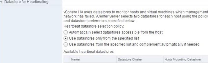
White Paper

     Types of failures..................................................................................................................................................................................................... 42
     Scenario Walk Through - Failure of Multiple Nodes in a Site........................................................................................................................ 44
     Scenario Walk Through - Failure of a Site ........................................................................................................................................................ 44
     Failure response summary ................................................................................................................................................................................... 44
     Witness Failure and Restore from Backup ........................................................................................................................................................ 46
     Failure Response Times ....................................................................................................................................................................................... 46
     Failure Capacity Considerations ......................................................................................................................................................................... 46
For more information .................................................................................................................................................................................................. 46
APPENDIX A – Shutting down a site ....................................................................................................................................................................... 47

© 2020 Cisco and/or its affiliates. All rights reserved. This document is Cisco Public Information.                                                                                                            Page 3 of 47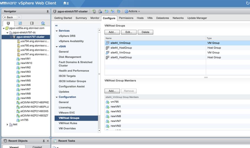
White Paper

Prerequisites
We recommend reviewing the Cisco HyperFlex™ HX Data Platform release notes, installation guide, and user guide before
proceeding with any configuration. The Data Platform should be installed and functioning as described in the installation guide.
Please contact Cisco® Support or your Cisco representative if you need assistance.

Introduction
This document is intended to provide operational guidance to supplement the administration guidance for Cisco HyperFlex stretch
clusters. The goal is to help Cisco HyperFlex users understand the characteristics of a stretch cluster and its day-2 operational
features, including its resilience in response to various failure scenarios. Knowledge of the architecture and components of the
solution is needed to for a full understanding. To this end, the document begins with an overview of general Cisco HyperFlex
components that apply to both regular and stretch clusters.

This document provides recommended configuration settings and deployment architectures for Cisco HyperFlex HX Data Platform
solutions specifically related to stretch cluster deployments. It is intended to be used in conjunction with product documentation.
For product documentation, please contact your Cisco representative.

Cisco HyperFlex HX Data Platform general overview: Components and environment
Cisco HyperFlex stretch clusters and regular clusters are built on common architectural components, but with some slight
differences for stretch clusters related to Cisco Unified Computing System™ (Cisco UCS®) domains, installation processes, and
failure modes. This section briefly examines the HX Data Platform components.

Cisco HyperFlex systems are designed with an end-to-end software-defined infrastructure that eliminates the compromises found
in first-generation products. Cisco HyperFlex systems combine software-defined computing in the form of Cisco UCS servers,
software-defined storage with the powerful Cisco HyperFlex HX Data Platform software, and software-defined networking (SDN)
with Cisco unified fabric that integrates smoothly with the Cisco Application Centric Infrastructure (Cisco ACI™) solution. With
hybrid or all-flash storage configurations, self-encrypting drive options, and a choice of management tools, Cisco HyperFlex
systems deliver a pre-integrated cluster that is up and running in an hour or less. With the capability to integrate Cisco UCS
servers as computing-only nodes, you can scale computing and storage resources independently to closely match your application
needs.

The following several sections discuss the individual components of the solution, including Cisco UCS, fabric interconnects, and
Cisco HyperFlex HX-Series nodes. These components are the same for both stretch clusters and traditional clusters.

Cisco Unified Computing System
The physical HX-Series node is deployed on a Cisco UCS 220 or 240 platform in either a hybrid or all-flash configuration.

A service profile is a software definition of a server and its LAN and SAN connectivity. A service profile defines a single server and
its storage and networking characteristics. Service profiles are stored in supported Cisco UCS 2nd, 3rd, and 4th generation Fabric
Interconnects and are managed through specific versions of Cisco UCS Manager (the web interface for the fabric interconnect) or
through purpose-written software using the API. When a service profile is deployed to a server, Cisco UCS Manager automatically
configures the server, adapters, fabric extenders, and fabric interconnects to match the configuration specified in the service
profile. This automation of device configuration reduces the number of manual steps required to configure servers, network
interface cards (NICs), host bus adapters (HBAs), and LAN and SAN switches.

The service profile for the HX-Series nodes is created during the cluster build process during installation and is applied to the
appropriate devices attached to the fabric interconnects (identified by part number and associated hardware). These profiles

© 2020 Cisco and/or its affiliates. All rights reserved. This document is Cisco Public Information.                           Page 4 of 47
White Paper

should have their own, easily identifiable names and should not be edited after creation. They are preconfigured by the Cisco
HyperFlex installer with the settings required for the Cisco HyperFlex system to operate securely and efficiently (VLANs, MAC
address pools, management IP addresses, quality-of-service [QoS] profiles, etc.).

Fabric interconnects
A Cisco UCS fabric interconnect is a networking switch or head unit to which the Cisco UCS chassis connects. The fabric
interconnect is a core part of Cisco UCS. Cisco UCS is designed to improve scalability and reduce the total cost of ownership
(TCO) of data centers by integrating all components into a single platform that acts as a single unit. Access to networks and
storage is provided through the Cisco UCS fabric interconnect. Each HX-Series node is dual connected, with one Small Form-
Factor Pluggable (SFP) port for each fabric interconnect for high availability. This design helps ensure that all virtual NICs (vNICs)
within Cisco UCS are dual connected as well, essentially guaranteeing node availability. The vNIC configuration is automated during
Cisco HyperFlex system installation and should not be altered.

Fabric interconnect traffic and architecture
Traffic through the fabric interconnect is of two general types: intracluster traffic (between nodes) and extracluster traffic (traffic
related to client machines or replication). All fabric interconnect configurations are managed, accessed, and modified through
Cisco UCS Manager.

Cisco UCS Manager requirements
Cisco UCS Manager is the interface used to set up the fabric interconnects for Cisco UCS service profiles and for general
hardware management. During installation, the Cisco HyperFlex installer verifies that the appropriate Cisco UCS Manager build is in
place for the Cisco HyperFlex system and that the hardware is running a supported firmware version. You are given the option to
upgrade these versions during installation if you need to do so.

Cisco recommends disabling the serial-over-LAN (SoL) feature after the deployment is complete because it is no longer needed
for VMware ESX configuration. You should also change any default or simple passwords that were used during the installation
process.

Virtual network interface cards
For an in-depth discussion of vNICs, see the following:
https://supportforums.cisco.com/document/29931/what-concept-behind-vnic-and-vhba-ucs

The vNICs for each virtual switch (vSwitch) are in a predefined order and should not be altered in Cisco UCS Manager or ESX. Any
changes to these (including active or standby status) could affect the functioning of the Cisco HyperFlex system.

East-west traffic
In a regular HX Data Platform cluster, east-west traffic on the fabric interconnect is networking traffic between HX-Series nodes.
This traffic is local to the system and does not travel out of the fabric interconnect to the upstream switch. This traffic has the
advantage of being extremely fast because of its low latency, low hop count, and high bandwidth. This traffic also is not subject to
external inspection because it never leaves the local system unless there is a NIC failure on one of the nodes.

In a stretch cluster, this traffic will need to traverse the site-to-site link between locations and so will exit a site’s individual fabric
interconnects to the stretch Layer 2 uplink switch and to the complementary site. It still occurs on the dedicated storage VLAN and
remains secure. See the following major section “Stretch cluster architecture” to understand why this happens.

© 2020 Cisco and/or its affiliates. All rights reserved. This document is Cisco Public Information.                                  Page 5 of 47
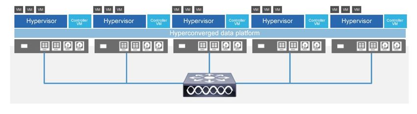
White Paper

North-south traffic
North-South traffic on the fabric interconnect is networking traffic that goes outside the fabric interconnect to an upstream switch
or router. North-south traffic occurs during external client machine access to Cisco HyperFlex hosted virtual machines or Cisco
HyperFlex system access to external services (Network Time Protocol [NTP], vCenter, Simple Network Management Protocol
[SNMP], etc.). This traffic may be subject to VLAN settings upstream. Because site-to-site stretch cluster traffic needs to traverse
the intersite link, a component of north-south traffic is a part of general storage traffic. For the purposes of this discussion,
however, north-south generally refers to traffic coming into and out of the cluster (regular or stretch) for interactions between
virtual machines and end users.

Upstream switches
Upstream or top-of-rack (ToR) switches are required to manage north-south traffic. You should configure the upstream switches
to accommodate nonnative VLANs. The Cisco HyperFlex HX Data Platform installer sets the VLANs as nonnative by default. In a
stretch cluster, these are the switches that mange Layer 2 adjacency for each site.

VLANs
The solution uses several VLANs to separate traffic. It uses management VLANs for VMware ESXi and Cisco HyperFlex control
virtual machines. It also uses VLANs for storage data traffic and for hypervisor data traffic (VMware vMotion traffic). You should use
a separate subnet and VLANs for each network.

Do not use VLAN 1, the default VLAN, because doing so can cause networking problems, especially if a disjointed Layer 2
configuration is used. Use a different VLAN.

Disjointed Layer 2 networks
If a disjointed Layer 2 network is a requirement for your environment, be sure that you read and understand the following
document:
https://www.cisco.com/c/en/us/solutions/collateral/data-center-virtualization/unified-computing/white_paper_c11-692008.html

You can simply add new vNICs for your use case. Cisco supports the manual addition of vNICs and virtual HBAs (vHBAs) to the
configuration. Please see the Cisco HyperFlex virtual server infrastructure (VSI) Cisco Validated Design for step-by-step
instructions about how to do this safely:
https://www.cisco.com/c/en/us/td/docs/unified_computing/ucs/UCS_CVDs/HX171_VSI_ESXi6U2.html

Follow the procedures outlined in the Cisco Validated Design. Do not use pin groups, because they may not properly prune the
traffic and can cause connectivity problems because the designated receiver may not be set correctly.

Cisco HyperFlex HX-Series data node
The HX-Series node itself, whether part of a regular cluster or stretch cluster, is composed of the software components required
to create the storage infrastructure for the system’s hypervisor. This infrastructure is created when the HX Data Platform that is
deployed during installation on the node. The HX Data Platform uses PCI pass-through, which removes storage (hardware)
operations from the hypervisor, giving the system high performance. The HX-Series nodes use special plug-ins for VMware called
VMware installation bundles (VIBs). These are used to redirect Network File System (NFS) data store traffic to the correct
distributed resource and to offload to hardware complex operations such as snapshots and cloning.

Figure 1 shows the typical HX-Series node architecture.

© 2020 Cisco and/or its affiliates. All rights reserved. This document is Cisco Public Information.                                 Page 6 of 47
White Paper
Figure 1. Typical Cisco Hyperflex HX-Series node
These nodes are incorporated into a distributed cluster using Apache ZooKeeper, as shown in Figure 2.
Figure 2. Cisco hyperflex distributed system
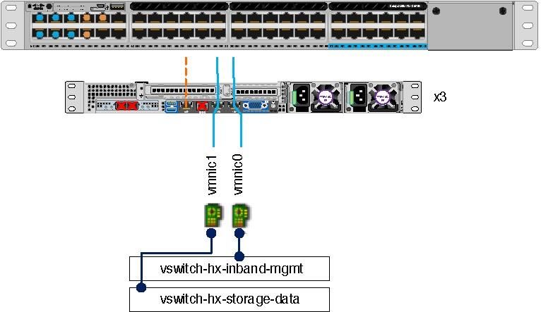
Each node consists of the virtual machine NIC (VMNIC) and vSwitch architecture shown in Figure 3.
Figure 3. Cisco Hyperflex HX-Series Node networking architecture
FIA FIB
vmnic0 vmnic1 vmnic2 vmnic3 vmnic4 vmnic5 vmnic6 vmnic7
vswitch-hx-inband-mgmnt vswitch-hx-storage-data vswitch-hx-vm-network vmotion
Mgmt Storage VMotion
vmk port vmk port vmk port
Storage Virtual machines
Storage
controller Storage
Management controller vMotion
management hypervisor
network data network
network data network
ESXi
HX-Series node
© 2020 Cisco and/or its affiliates. All rights reserved. This document is Cisco Public Information. Page 7 of 47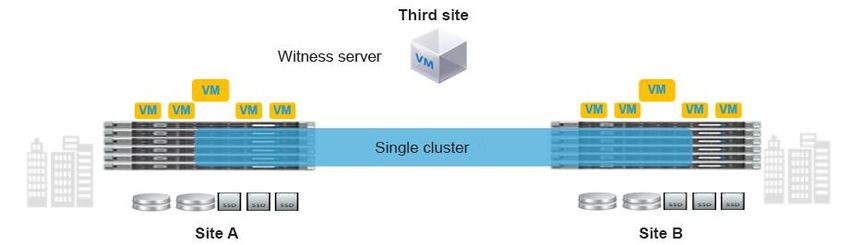
White Paper

Management interfaces: Cisco HyperFlex Connect and VMware vCenter Plug-in
Cisco HyperFlex Connect is the native HTML 5.0 user interface for the cluster. The vCenter Plug-in for the Cisco HyperFlex system
is another management interface available in vCenter after the cluster is deployed. In newer deployments the vCenter plugin is not
installed by default. The HTML 5 plugin is installed separately after the cluster is built. HX Connect and the plugin are separate
interfaces. Both are accessed through HTTPS in a web browser and are subject to the same user management (including role-
based access control [RBAC]) that is available for the command-line interface (CLI) and the API

Apache ZooKeeper
ZooKeeper is essentially a centralized service for distributed systems to a hierarchical key-value store. It is used to provide a
distributed configuration service, synchronization service, and naming registry for large distributed systems.

ZooKeeper's architecture supports high availability through redundant services. Clients can thus ask another ZooKeeper leader if
the first fails to answer. ZooKeeper nodes store their data in a hierarchical name space, much like a file system or a tree data
structure. Clients can read from and write to the nodes and in this way have a shared configuration service. ZooKeeper can be
viewed as an atomic broadcast system through which updates are totally ordered.

ZooKeeper offers these main features:

       ●   Reliable system: The system is very reliable because it keeps working even if a node fails.
       ●   Simple architecture: The architecture of ZooKeeper is quite simple; it uses a shared hierarchical name space, which helps in
           coordinating processes.
       ●   Fast processing: ZooKeeper is especially fast for read-dominant workloads.
       ●   Scalable: The performance of ZooKeeper can be improved by adding nodes.

VMware vCenter
The Cisco HyperFlex HX Data Platform requires VMware vCenter to be deployed to manage certain aspects of cluster creation
such as VMware ESX clustering for VMware High Availability (HA) and Distributed Resource Scheduler (DRS), virtual machine
deployment, user authentication, and various data store operations. The vCenter Plug-in for the Cisco HyperFlex system is a
management utility that integrates seamlessly within vCenter and allows comprehensive administration, management, and
reporting for the cluster.

VMware ESX
ESX is the hypervisor component in the solution. It abstracts node computing and memory hardware for the guest virtual machines.
The HX Data Platform integrates closely with ESX to facilitate network and storage virtualization.

Virtual machines
The Cisco HyperFlex environment provides storage for the guest virtual machines deployed in ESX using VLAN segmented
networking. The virtual machines are available for external resources, as is typical of any elastic infrastructure deployment.

Client machines
Client machines are defined here as external hosts that need to access resources deployed in the Cisco HyperFlex system. These
resources can be anything from end users to other servers in a distributed application architecture. These clients access the
system from external networks and are always isolated from any Cisco HyperFlex internal traffic through network segmentation,
firewalling, and whitelisting rules.

© 2020 Cisco and/or its affiliates. All rights reserved. This document is Cisco Public Information.                              Page 8 of 47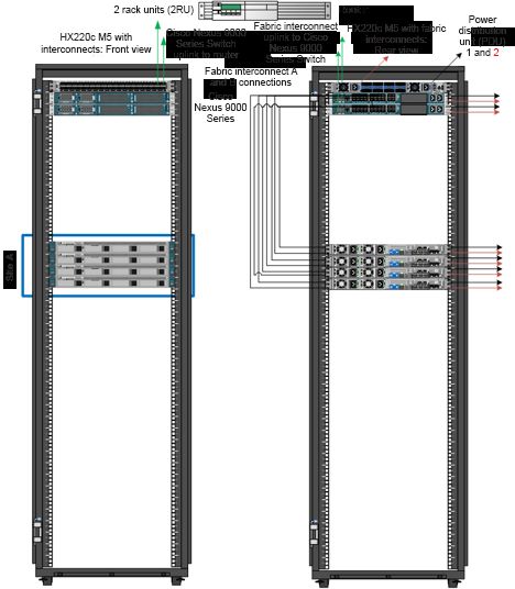
White Paper

Cisco HyperFlex HX Stretch Clusters
This section provides an overview of Cisco HyperFlex stretch clusters. It details some of the business reasons for deploying such a
cluster. It also discusses some of the physical limitations of such a cluster.

What is a Stretch Cluster
A stretch cluster is distinct from a non-stretch, or normal, cluster, in that it is designed to offer business continuance in the event
of a significant disaster at a data center location. A stretch cluster is geographically redundant, meaning that part of the cluster
resides in one physical location and another part resides in a second location. The cluster also requires a “tie breaker” or “witness”
component, which should reside in a third, separate location. The goal of this design is to help ensure that the virtual infrastructure
remains available even in the event of the complete loss of one site. Of course, many lesser types of failures also can occur, and
the system is highly available in the event of these as well. All of these scenarios are discussed later in this document.

People often mistakenly think that a stretch cluster is a set of multiple single clusters. This is not the case. A stretch cluster is, in
fact, a single distributed entity and behaves as such in most circumstances. There are a few differences between a normal cluster
and a stretch cluster, however. These arise solely from the fact that a stretch cluster must meet some special requirements to
provide geographical redundancy for deployments that require it. Georedundancy introduces a few new requirements for the
cluster so that certain conditions, such as split brain and node quorum, are handled properly. These are discussed in the following
sections.

Figure 4 shows the main features of a stretch cluster.

Figure 4.        Three main components of a stretch cluster deployment

Note the following characteristics of a stretch cluster:

       ●    A stretch cluster is a single cluster with nodes geographically distributed at different locations.
       ●    Storage is mirrored locally and across each site (but not to the tie-breaker witness).
       ●    Sites need to be connected over a low-latency network to meet the write requirements for applications and for a good end-
            user experience.
       ●    Geographic failover (virtual machine) is like failover in a regular cluster.
       ●    Node failure in a site is like node failure in a regular cluster.
       ●    Split brain is a condition in which nodes at either site cannot see each other. This condition can lead to problems if a node
            quorum cannot be determined (so that virtual machines know where to run). Split brain is caused by:
            ◦ Network failure

© 2020 Cisco and/or its affiliates. All rights reserved. This document is Cisco Public Information.                                Page 9 of 47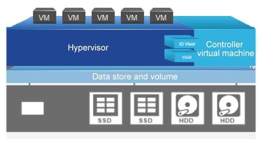
White Paper

           ◦ Site failure
       ●   Stretch clusters have a witness: an entity hosted on a third site that is responsible for deciding which site becomes primary
           after a split-brain condition.

Business need for a stretch cluster
Businesses require planning and preparation to help ensure business continuity after serious incidents or disasters and to resume
normal operations within a reasonably short period. Business continuity is the capability of an organization to maintain essential
functions during, as well as after, a disaster. It includes three main elements:

       ●   Resilience: Critical business functions and the supporting infrastructure must be designed so that that they are materially
           unaffected by relevant disruptions: for example, through the use of redundancy and spare capacity.
       ●   Recovery: Organizations must have in place arrangements to recover or restore critical and less critical business functions
           that fail for some reason.
       ●   Contingency: An organization must establish a generalized capability and readiness to allow it cope effectively with
           whatever major incidents and disasters may occur, including those that were not, and perhaps could not have been,
           foreseen. Contingency preparations constitute a last-resort response if resilience and recovery arrangements should prove
           inadequate in practice.

Stretch cluster physical limitations
Some applications, specifically databases, require write latency of less than 20 milliseconds (ms). Many other applications require
latency of less 10 ms to avoid problems with the application. To meet these requirements, the round-trip time (RTT) network
latency on the stretch link between sites in a stretch cluster should be less than 5 ms. The speed of light (3e8 m/s) at the
maximum recommended stretch cluster site distance of 100 km (approximately 62 miles) introduces about 1 ms of latency by
itself. In addition, time is needed for code path and link hops (from node to fabric interconnect to switch), which also plays a role in
determining the maximum site-to-site recommended distance.

This section details the components in a typical Cisco HyperFlex deployment. Note that to achieve a secure environment, the
various parts must be hardened as needed.

Solution components
A traditional Cisco HyperFlex single-cluster deployment consists of HX-Series nodes in Cisco UCS connected to each other and
the upstream switch through a pair of fabric interconnects. A fabric interconnect pair may include one or more clusters. A stretch
cluster requires two independent Cisco UCS domains: one for each site. Therefore, a total of four fabric interconnects (two pairs)
are required for a stretch cluster. Other clusters can share the same fabric interconnects.

Figures 5 and 6 show typical physical layouts for this kind of deployment. Figure 5 shows a single site with its cabling and
independent Cisco UCS domain. Figure 6 shows the racks for site A and site B in a stretch cluster with their respective fabric
interconnects and upstream switches. This is an 8-node (4+4) stretch cluster with Cisco HyperFlex HX220c nodes at each
location.

© 2020 Cisco and/or its affiliates. All rights reserved. This document is Cisco Public Information.                             Page 10 of 47
White Paper
Figure 5. Site a for a stretch cluster deployment showing a single-site rack: the site contains 4 HX220c M5 nodes and 2 fabric interconnects
with a single uplink switch for the stretch layer 2 network connecting to site b
© 2020 Cisco and/or its affiliates. All rights reserved. This document is Cisco Public Information. Page 11 of 47White Paper
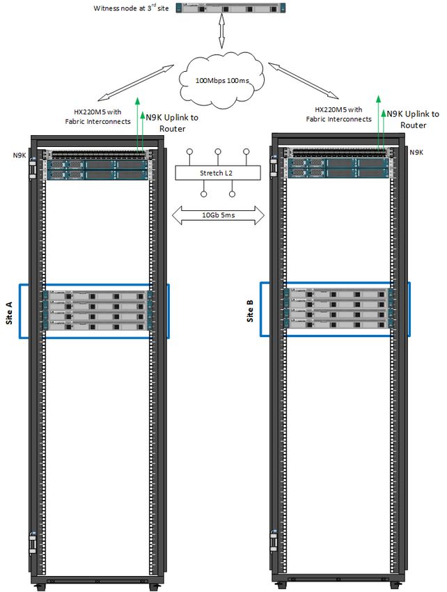
Figure 6. Rack diagram showing site a and site b with their respective fabric interconnects and a logical third site at another location for the
stretch cluster witness
© 2020 Cisco and/or its affiliates. All rights reserved. This document is Cisco Public Information. Page 12 of 47White Paper
Stretch cluster architecture
This section discusses the specific deployment needs for a stretch cluster, including hardware, networking configuration, VMware
requirements (ESXi and vCenter), failure sizing, and characteristics of the witness (Figure 7). VMware vSphere Enterprise Plus is
required because Cisco HyperFlex stretch clusters rely on advanced DRS capabilities available only in that premium edition. The
requirements are the same across all stacks (even for non-hyperconverged infrastructure [HCI] or traditional storage) that
implement stretch or metropolitan clusters on VMware.
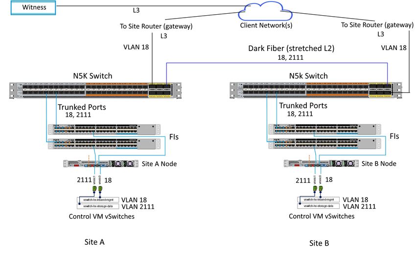
Figure 7. General stretch cluster network
The first consideration in deploying a stretch cluster is building the proper site-to-site network. A stretch cluster requires a
minimum of 10 Gigabit Ethernet connectivity and 5-ms RTT latency on the link. The link needs to be stretch Layer 2 to help ensure
network space adjacency for the data storage VLAN network that is used for storage communication. The network between sites
requires the following characteristics:
● 10 Gbps (dedicated) for the storage data VLAN
● 5-ms RTT latency between the two active sites
● Data VLAN and management VLAN on a stretch Layer 2 VLAN
● Stretch Layer 2 VLAN between the two sites
◦ Dark fiber and dense wavelength-division multiplexing (DWDM) Layer 2 and 3 technologies are supported.
◦ The solution is not currently qualified for Virtual Extensible LAN (VXLAN) unless used with ACI.
◦ Stretch Layer 2 characteristics
◦ The stretch data VLAN should use jumbo maximum transmission units (MTUs) for best performance. The installer allows
for deployment using an MTU of 1500, however.
© 2020 Cisco and/or its affiliates. All rights reserved. This document is Cisco Public Information. Page 13 of 47White Paper
◦ The Cisco Nexus® 5000 Series Switches are slightly different than the Cisco Nexus 7000 and 9000 Series Switches. The
default network-QoS policy does not accept jumbo MTUs, but you can set up jumbo switch policy across the switches.
◦ Test the RTT ping using VMkping –I VMk1 -d -s 8972 x.x.x.x from any ESXi host in your cluster. This check is also
performed by the installer, and if it fails, the installation process will not proceed.
● 100 Mbps and 100-ms RTT latency between the active sites and the witness site
● Different drives types are supported with different nodes limits. See the release notes for your running or target version to
determine which drives and nodes you can use. For example, there are LFF drive restrictions and NVME drives began
support in 4.0.2x and onward for the HX220 node type.
Limitations
Some deployment limitations exist for stretch clusters related to the qualified hardware. Most of these limitations are not based on
technical factors but simply reflect test bandwidth and the release cycle. After these items have been qualified, they will be
removed from the unsupported-features list, and these capabilities will be available for general deployment. Check the minor
version release notes periodically for changes in the support listings.
Minimum and maximum configuration limitations are as follows:
● Minimum
◦ Two fabric interconnects per site
◦ Two nodes per site
◦ One witness
◦ One vCenter instance
◦ Replication factor: 2+2
● Maximum
◦ Two fabric interconnects per site
◦ 2:1 maximum ratio for compute to converged nodes
◦ Compute nodes can be added asymmetrically with no restriction
◦ 16 small-form-factor (SFF) converged nodes per site (32 total, max cluster 64 with compute)
◦ 8 large-form-factor (LFF) converged nodes per site (16 total, max cluster 48 with compute)
◦ One witness
◦ One vCenter or vCenter with HA instance if there is no database update lag
◦ Replication factor: 2+2
Stretch cluster support limitations are as follows:
● Self-encrypting drives (SEDs) are not supported.
● Compute-only nodes are supported in HyperFlex 3.5 or higher with a 2:1 ratio to converged nodes. Verify the ratio in the
Release Notes for your version.
● ESXi is the only supported hypervisor at this time. Check the release notes for your HX version to see the recommended
ESXi version.
© 2020 Cisco and/or its affiliates. All rights reserved. This document is Cisco Public Information. Page 14 of 47White Paper
● Cisco HyperFlex native replication is supported in HyperFlex 3.5 and greater.
● Expansion of an existing cluster to a stretch cluster is not supported.
● Stretch clusters are supported only in fresh installations. Upgrade from a standalone cluster to a stretch cluster
configuration is not supported.
● Stretch Clusters must be symmetric (converged nodes). For production environments, this includes Fabric Interconnects.
● Stretch Clusters must be expanded symmetrically (converged nodes). See the admin guide for your version of HX for
workflow details.
● Stretch Clusters can be built and/or expanded asymmetrically with compute nodes.
● Online rolling upgrades are supported only for the HX Data Platform. Cisco UCS Manager upgrades must be performed
manually one node at a time.
● Stretch clusters are supported on Cisco M5 nodes only. M4 nodes are not supported.
● Logical availability zones are not currently supported in stretch clusters.
● The witness requires ESXi at the third site (cloud deployment is not currently supported).
● Disk reshuffling is not supported (e.g., adding empty nodes and “leveling” the disks out)
● Hardware offload (acceleration) cards are supported starting in HXDP version 4.0.2b and greater
● Node removal is not supported
● Single Socket nodes may or may not be supported, depending on your version of HX. Please see the Release Notes.
About Zones
While logical availability zones are not currently supported in stretch cluster deployments, you may notice that zone information is
available when running the stcli cluster get-zone command as show below:
root@SpringpathControllerOHCWUK9X3N:~# stcli cluster get-zone
zones:
----------------------------------------
pNodes:
----------------------------------------
state: ready
name: 192.168.53.136
----------------------------------------
state: ready
name: 192.168.53.135
----------------------------------------
zoneId: 51733a6b98df9784:4f8fc27070894bf4
numNodes: 2
----------------------------------------
pNodes:
----------------------------------------
state: ready
name: 192.168.53.138
----------------------------------------
state: ready
name: 192.168.53.137
© 2020 Cisco and/or its affiliates. All rights reserved. This document is Cisco Public Information. Page 15 of 47White Paper
----------------------------------------
zoneId: 7b04a6600e3e3ee5:54c7224773a14a9a
numNodes: 2
----------------------------------------
isClusterZoneCompliant: True
zoneType: physical
isZoneEnabled: True
numZones: 2
LAZ and stretch cluster both are implemented using a basic feature called "zones" and that's why you see 'zone' in some of the
output. You will not see "logical zones" which is what would appear under LAZ.
note the “zoneType” on the get-zone output.
On stretch cluster: “zoneType: physical”
On Cluster with LAZ : “zoneType: logical”
Hardware Matching
Stretch Clusters require identical hardware at both sites. This includes node count, type, and drives per node as well. This also applies to
expansion. You must expand in converged node pairs.
There are some exceptions to the hardware symmetry requirement. Compute resources are not required to be symmetric between sites. You can
have more compute-only nodes on one site than the other. However, care should be taken since a failure scenario from one site with large
compute resources to another site with reduced resources may not be sized properly to run the VMs that are started on the surviving site.
Mixing CPU generations is supported within the same family as well. For example, it is ok to mix 8180 Skylake CPUs with 6258R Cascade Lake CPUs.
You must, however, size for the less powerful CPU.
A Stretch Cluster will work, i.e., deploy properly and functional as expected, if the FIs are different between sites, but identical within the site. This
can be useful for lab and testing environments but is not supported by Cisco for production. FIs must be identical within a site and between sites
for production.
Overlay Networks
Only certain overlay networks are currently qualified for use with Stretch Clusters. OTV is qualified for use with Stretch Cluster. This means
however, that VXLAN and NSX are not supported as stand-alone overlay protocols. VXLAN is supported only with ACI. See the “More Information”
section for the CVD describing this deployment.
Cisco Overlay Transport Virtualization (OTV), supported on Nexus Switches, is a networking technology that allows relaying layer 2 (L2) networks
over layer 3 (L3) network segments. OTV is important for Stretch Clusters that require stretched L2 storage and management networks when a
dedicated dark fiber type site-to-site connection is not available. The tested and validated OTV design is shown below.
© 2020 Cisco and/or its affiliates. All rights reserved. This document is Cisco Public Information. Page 16 of 47White Paper
This OTV design was tested for the various failure modes discussed later. It was configured to meet the bandwidth and latency requirements
necessary for the proper operation of the Stretch Cluster. It is important to note that layering over L3 can introduce latency since the routed
network will necessarily have additional device to device hops. When designing and deploying this type of architecture you must ensure that you
are still within the site-to-site communication specification for bandwidth and latency.
The following references are for OTV on Nexus:
https://www.cisco.com/c/en/us/solutions/data-center-virtualization/overlay-transport-virtualization-otv/index.html
https://community.cisco.com/t5/data-center-documents/understanding-overlay-transport-virtualization-otv/ta-p/3151502
Fabric interconnects
Stretch clusters have a specific set of fabric interconnect requirements. Each site is built using its own pair of fabric interconnects
in an independent Cisco UCS domain. Therefore, a total of four fabric interconnects are required. The stretch cluster requires a
symmetric deployment, meaning that each site must have the same number and type of fabric interconnects and converged
nodes. If site A has 4 hybrid nodes, then site B must also have 4 hybrid nodes. As of Cisco HyperFlex 3.0, the maximum cluster
size is 8 nodes per site, for a total of 16 (8 + 8). This has increased in 3.5 and above to 16 converged nodes per site (SFF) with
up to a 2:1 compute node ratio for a maximum mixed count of 32 per site. Limits for LFF drives are different. See the release
notes for your version of HX to get the latest information on the number and type of supported nodes.
Fabric interconnect and node configuration details are summarized here:
● A total of four fabric interconnects are required, one pair at each site) in unique Cisco UCS domains.
© 2020 Cisco and/or its affiliates. All rights reserved. This document is Cisco Public Information. Page 17 of 47White Paper
● Do not mix fabric interconnect models within a domain.
● For the fabric interconnects, Cisco UCS Manager Release 3.2(3e) is required.
● Existing fabric interconnects are supported as long as they work with Cisco M5 nodes.
● Nodes requirements are as follows:
◦ You must have the same number and type of nodes per site: All flash or all hybrid.
◦ The maximum cluster size is 16 converged nodes per site starting in 3.5 with a 2:1 maximum compute ratio (max 32
mixed nodes per site).
◦ These requirements and maximums change frequently, consult the Release Notes for your version.
Fabric Interconnects Uplink Best Practices
Care should be taken with all deployments of HX when uplinking the Fabric Interconnects to your TOR/edge switches. The best
practice surrounding this is designed to make sure that Spanning Tree Protocol (STP) loops are avoided. In a normal cluster these
loops will cause FI takeover problems. Due to the multi-domain nature of a stretch cluster, STP storms can bring the system
down. When uplinking the FIs to your redundant swtiches, the virtual port channel (VPC) ports should be set to edge trunk mode
so that they do not participate in STP.
This behavior is called out in several location within Cisco documentation but is reiterated here for convenience. For example, the
following document call out using spanning-tree port type edge trunk or the need to disable spanning tree on ports connecting to
the FIs from upstream switches:
• https://www.cisco.com/c/en/us/td/docs/hyperconverged_systems/HyperFlex_HX_DataPlatformSoftware/Network_Extern
al_Storage_Management_Guide/b_HyperFlex_Systems_Network_and_External_Storage_Management_Guide_3_0/b_Hy
perFlex_Systems_Network_and_External_Storage_Management_Guide_3_0_chapter_01.html
Cisco FIs appear on the network as a collection of endpoints versus another network switch. Internally, the FIs do not participate in
spanning-tree protocol (STP) domains, and the FIs cannot form a network loop, as they are not connected to each other with a
layer 2 Ethernet link. The upstream root bridges make all link up/down decisions through STP
.
Uplinks need to be connected and active from both FIs. For redundancy, you can use multiple uplinks on each FI, either as 802.3ad
Link Aggregation Control Protocol (LACP) port-channels or using individual links. For the best level of performance and
redundancy, make uplinks LACP port-channels to multiple upstream Cisco switches using the virtual port channel (vPC) feature.
Using vPC uplinks allows all uplinks to be active passing data. This also protects against any individual link failure and the failure of
an upstream switch. Other uplink configurations can be redundant, but spanning-tree protocol loop avoidance may disable links if
vPC is unavailable.
When setting the uplinks from the FI as VPC port channels you also need to set the downlink ports on the (e.g.) Nexus 9k to
“spanning tree edge” instead of “spanning tree normal”, since the FIs don’t participate in STP. In the absence of this configuration,
a spanning tree storm in the N9k will cause a traffic blackhole for HX storage traffic. This in turn will affect all HX traffic in a stretch
cluster. In standard clusters, the problem happens only when there is an FI failover.
In clusters without the ability to use vPC or LACP based link aggregation for redundancy, you should use disjoint layer 2.
© 2020 Cisco and/or its affiliates. All rights reserved. This document is Cisco Public Information. Page 18 of 47White Paper
VMware vCenter
vCenter is a critical component for normal clusters and is vital for a stretch cluster. vCenter, with HA and DRS configured
automatically manages virtual machine movement in the event of a site failure. The use of virtual machine host groups in the
preferred mode, in which virtual machines are pinned to a site for the purpose of local computing and read I/O, is required for
optimal performance in a stretch deployment. Site host groups and the corresponding affinities are created automatically at build
time by the Cisco HyperFlex installer.
Data stores also maintain site affinity using host groups as the mechanism to locate the primary copy of virtual machine data. This
approach is used to facilitate the asymmetric I/O mechanism that a stretch cluster uses to increase the cluster response time by
localizing read I/O while distributing write I/O (two local-site copies and two remote-site copies). Because both sites in a stretch
cluster are active, virtual machines at one site or the other do not suffer any “second-class citizen” type scenarios, in which one
site has preferential performance relative to another.
In a stretch cluster deployment, a single instance of vCenter is used for both sites. The best approach is to locate this instance at a
third location so that it is not affected by site loss. Co-residency with the witness is often the preferred choice because the witness
site is required anyway. Nested vCenter (i.e., running the cluster’s vCenter instance on the cluster itself) is not supported. vCenter
HA (VCHA) is supported with Stretch Cluster. Be aware the VCHA is a high availability deployment of vCenter itself and does not
refer to the enabling HA on vCenter (which is a separate requirement for proper cluster failover behavior).
In the vCenter instance, the stretch cluster corresponds to a single ESXi cluster. Be sure to verify that HA and DRS are set up for
the stretch cluster.
If the need arises to move the cluster from one vCenter to a new vCenter deployment or a different existing vCenter instance, it
will be necessary to perform a cluster re-register. Be sure to see the admin guide for detailed notes, but the general workflow is
as follows: Create the cluster object in the new vCenter instance and add the cluster ESXi hosts manually. Be sure the HA/DRS is
enabled. The re-register is conducted using STCLI from any node or the CIP-M address.
admin@ControllerE2L5LYS7JZ:~$ stcli cluster reregister
usage: stcli cluster reregister [-h] --vcenter-datacenter NEWDATACENTER
--vcenter-cluster NEWVCENTERCLUSTER
--vcenter-url NEWVCENTERURL
[--vcenter-sso-url NEWVCENTERSSOURL]
--vcenter-user NEWVCENTERUSER
stcli cluster reregister: error: argument --vcenter-datacenter is required
In a non-stretched cluster this is all that is required to remove the cluster from one vCenter instance and move it to a new one. A
stretch cluster, however, requires a few manual steps to complete the process. This is because Host Groups and Affinity Rules are
not transferred in the re-registration process. Please note that ICPM needs to be accessible between hosts and vCenter for re-
registration to function properly.
A stretch cluster relies on a specific naming convention when interfacing with vCenter for implementation of the affinity rules. This
is set up automatically, in advance, with the HX Installer when the cluster sites are built. The host group and affinity group naming
must follow this convention: _{HostGroup, VmGroup, SiteAffinityRule} when rebuilding the groups and rules on the
© 2020 Cisco and/or its affiliates. All rights reserved. This document is Cisco Public Information. Page 19 of 47White Paper new vCenter host. See the screens below for an example. Here, site 1 is called fi47 and site 2 is fi48. Note the naming convention. VMware vCenter HA Settings The settings below are recommended for use in HX Stretch Clusters. This table details the most common settings in vSphere HA that are typically asked about during custom configuration. The screens shots are representative of vCenter 6.5. The cluster will work as designed using the default installation values. If you do not see a value listed below, keep it at the default. vSphere HA Settings © 2020 Cisco and/or its affiliates. All rights reserved. This document is Cisco Public Information. Page 20 of 47
White Paper

vSphere HA                    Turn on HA. Keep Proactive HA disabled.

Host Monitoring               Enabled

Virtual Machine               Customer Preference – Disabled by default
Monitoring

© 2020 Cisco and/or its affiliates. All rights reserved. This document is Cisco Public Information.   Page 21 of 47
White Paper

Failure conditions Host monitoring is enabled, Response for Host Isolation is set to Power off and Restart VMs. For PDL and APD,
and VM Response select Power off and Restart from the drop downs.

Admission Control Set to disable

© 2020 Cisco and/or its affiliates. All rights reserved. This document is Cisco Public Information.                   Page 22 of 47
White Paper

Datastore                     “Use datastores only from the specified list” and select HX datastores.
Heartbeats
                              https://kb.vmware.com/s/article/2004739

Advanced Settings
das.usedefaultisolationaddress                      False
das.isolationaddress0                               IP address for Management Network Gateway
das.isolationaddress1                               Existing IP address that is outside cluster. Do not use FI VIPs, Cluster IP (CIP), or cluster host IP

Witness configuration
A quorum is the minimum number of votes that a distributed transaction must obtain to be allowed to perform an operation in a
distributed system. A quorum-based technique is implemented to enforce consistent operation in a distributed system. The
witness node serves this function. In the event of a split-brain condition, in which both sites are still available but unable to
communicate with each other, a virtual machine site leader must be established so that two instances of the same virtual machine
are not brought online by HA.

The witness is deployed at a third site and is delivered as an open virtual appliance (OVA) file for use in an infrastructure ESXi
deployment at that location. The witness runs an instance of ZooKeeper (see the “Apache ZooKeeper” section earlier in this
document for details), becomes a cluster member, and contributes its vote when needed to break a tie.

The witness node must have the following characteristics:

       ●   A third independent site is needed to host the witness virtual machine.
       ●   IP address and connectivity for the witness virtual machine is needed to each stretch cluster site.
       ●   The witness must be on a routable Layer 3 network.
       ●   The minimum requirements for the witness node are as follows:
           ◦ Virtual CPUs (vCPUs): 4
           ◦ Memory: 8 GB
           ◦ Storage: 40 GB
           ◦ HA: Optional for the witness node
       ●   Latency of at most 100-ms RTT to each site is required.

© 2020 Cisco and/or its affiliates. All rights reserved. This document is Cisco Public Information.                                             Page 23 of 47
White Paper
● Bandwidth of at least 100 Mbps to each site is required.
● For fastest site-to-site failover times, an RTT latency to the witness of less than 10ms is optimal.
● The node must be deployed separately before the Cisco HyperFlex installer stretch cluster workflow is run.
● The witness behaves as a quorum node, if you are reinstalling the cluster the witness must be reinstalled as well.
● THERE IS ONE WITNESS PER CLUSTER. MULTIPLE CLUSTERS CANNOT USE THE SAME WITNESS.
While no user data is being sent between the sites and the witness, some storage-cluster metadata traffic is transmitted to the
witness site. This traffic is the reason for the 100-Mbps requirement and is in line with competitive products. The witness
connection to each site requires 100 Mbps bandwidth with a 100 ms RTT in order to function properly. It is recommended to use
a connection with a 100 ms latency for proper system failover behavior. For large clusters and for the best site-to-site failover
performance, Cisco recommends witness-to-site latency on the order of 10 ms.
The witness is currently not supported in cloud deployments because of testing limitations. The OVA file has been tested and is
supported for the ESXi platform.
If you need to patch the witness virtual machine for any reason, you can take the witness offline temporarily, implement the update,
and bring the witness back online. Cisco recommends that you stage this process and practice it on a test witness to help ensure
timely reintroduction of the production system when you implement the actual update. The cluster must be in a healthy condition to
conduct this operation. If you need assistance, please contact the Cisco Technical Assistance Center (TAC).
I/O path in a stretch cluster
A stretch cluster is in active-active mode at each site: that is, primary copies and read traffic occur for each virtual machine at each
site. There is no concept of an active-standby configuration in a stretch cluster. IO Visor, the Cisco HyperFlex file system proxy
manager, dictates which nodes service which read and write requests. In general, a stretch cluster behaves the same way as a
normal cluster with modifications for host affinity and certain failure scenarios (see the “Stretch cluster failure modes” section later
in this document). With virtual machine affinity and a replication factor of 2 + 2, the read and write dynamics are as described in the
following sections.
Read path
Taking advantage of the host group affinity, all read operations for virtual machine data are served locally, meaning that they come
from the nodes at the site to which the data store for the virtual machine is assigned. Read operations are first serviced by the
node cache if they are available there. If they are not available, they are read from persistent disk space (in a hybrid node) and
served to the end user. The read cache in a stretch cluster behaves the same way as in a normal hybrid or all-flash cluster with the
exception of local service based on host affinity.
Write path
Write operations in a stretch cluster are a little more complicated than read operations. This is the case because to achieve data
integrity, a write operation is not acknowledged as committed to the virtual machine guest operating system until all copies, local
and remote, are internally committed to disk. This means that a virtual machine with affinity to site A will write its two local copies
to site A while synchronously writing its two remote copies to site B. Again, IO Visor determines which nodes are used to complete
each write operation.
The Cisco HyperFlex file system waits indefinitely for write operations to be acknowledged from all active copies. Thus, if certain
nodes or disks that host a copy of data for which a write operation is being implemented are removed, write operations will stall
© 2020 Cisco and/or its affiliates. All rights reserved. This document is Cisco Public Information. Page 24 of 47You can also read