THE LEAD ORE DRESSING FLOORS AT GLENDALOUGH AND GLENDASAN, COUNTY WICKLOW 1825-1923: A HISTORY, SURVEY AND INTERPRETATION OF EXTANT REMAINS
←
→
Page content transcription
If your browser does not render page correctly, please read the page content below
THE LEAD ORE DRESSING FLOORS AT
                             GLENDALOUGH AND GLENDASAN, COUNTY
                              WICKLOW 1825-1923: A HISTORY, SURVEY
                                AND INTERPRETATION OF EXTANT
                                           REMAINS

                                                 Sharron P. Schwartz and Martin F. Critchley

Abstract: This article highlights the considerable archaeological and heritage value of the dressing floors of the former
Luganure silver-lead mines worked by the Mining Company of Ireland (1824-1890) situated in the parallel valleys of
Glendalough and Glendasan and separated by Camaderry Mountain. It also discusses a small early twentieth century
treatment plant in Glendalough. During the nineteenth century the Luganure mines were Ireland’s most important lead
mining centre, leaving behind an exceptionally well-preserved relict rural-industrial landscape, particularly with regard
to the dressing floors which are the focus of this paper. These are the most complete lead ore processing sites in Ireland
and are comparable in importance to many contemporaneous lead dressing floors in uplands regions of neighbouring
Britain. The archaeology takes on added significance in the case of these sites, as the documentary record is slight at best
due to the absence of most of the Mining Company of Ireland’s records, leaving the historian with pared down half
yearly reports of shareholders’ meetings which do not contain much technical detail and often lump all the sites together
as the Luganure Mines. Although the mines lay close to the Seven Churches (Glendalough), a tourist trap that was well
photographed in the Victorian period, no nineteenth century photographs of the nearby mines have yet been discovered
that might aid an understanding of surviving features. Perhaps they were unaesthetically pleasing to many Victorians,
such as the walker descending the dale-head past the mines, who thought that they ‘rather spoiled it’ (BW 1879);
contemporary maps contain sparse detail and no archaeological excavations have ever been conducted. This paper
interprets the remarkable assemblage of features at these dressing floors based on documentary sources, aerial
photographs, historic mapping, detailed surveying and field study and attempts to set their archaeology within a
comparative context with similar contemporaneous sites in Britain. Finally, it makes a plea for an increased salience and
improved listing regimen in Ireland for important post-1700 industrial landscapes that are of considerable heritage
value. Journal of the Mining Heritage Trust of Ireland, 12, 2012, 5-52.

A BRIEF HISTORY OF THE LUGANURE MINES                                  patrons, directors and shareholders read like a roll call of the
                                                                       most eminent Irish landed families, politicians, industrialists
Current narratives of the Glendalough area in County Wicklow           and commercial traders for much of the nineteenth century.
focus almost exclusively on its monastic heritage. Yet, from           The MCI were, on the whole, fortunate in their choice of
the thirteenth century the area has been witness to significant        mines, for they managed to select some of the best prospects
industry. This was firstly in the shape of extensive charcoal          in the island, including the Slieveardagh Collieries in County
production to feed iron smelters, a ‘smash and grab’ operation,        Tipperary, the Knockmahon copper mines at Waterford, and
particularly in the seventeenth and eighteenth centuries, that         the Ballycorus lead mine and smelting works near Dublin.
laid waste to the landscape by denuding it of its deciduous tree       Their Wicklow mines became the richest and most successful
cover. Secondly, and more recently, the area has seen deep             lead producers in Ireland, with Hall noting that about 80 per
lode hard rock mining and mineral processing, firstly by the           cent of all nineteenth century Irish lead production was
Mining Company of Ireland (MCI) (Cowman 2007), and then                accounted for by the Luganure Mines (Hall 1921, 55).
by various enterprises spanning several decades initiated by
the Wynne family who purchased the mines and land from the             In 1825 the MCI acquired the lead mine and materials of the
MCI in the late nineteenth century. Industrial activity through        Glendalough Mine Company. This company had been set up
the ages has profoundly shaped the geomorphology of this               by geologist, Thomas Weaver of Cronebane1 who is credited
area, yet is a largely neglected narrative.                            with the discovery of the South Luganure Lode which he had
                                                                       commenced working in 1807 (Stephens 1812). Fraser noted in
The Mining Company of Ireland (1824-1891) was set up as a              1801 that a lode of lead had been discovered near the Seven
joint stock company of £200,000 divided into 20,000 shares of          Churches in Glendalough, which is a probable reference to
£10 each (£140,000 issued) and received Royal Assent in July           Weaver’s activities (Fraser 1801, 14). In June of 1809 Weaver
1824 during the London stock market boom of 1824-25. With
its motto, ‘Industry, Economy and Perseverance’, it was                1 Weaver was a shareholder and resident manager of the Associated Irish
initiated by a group of philanthropic gentlemen and its list of        Mine Company at Avoca, Co. Wicklow.

                                                                   5
6
Journal of the Mining Heritage Trust of Ireland No. 12
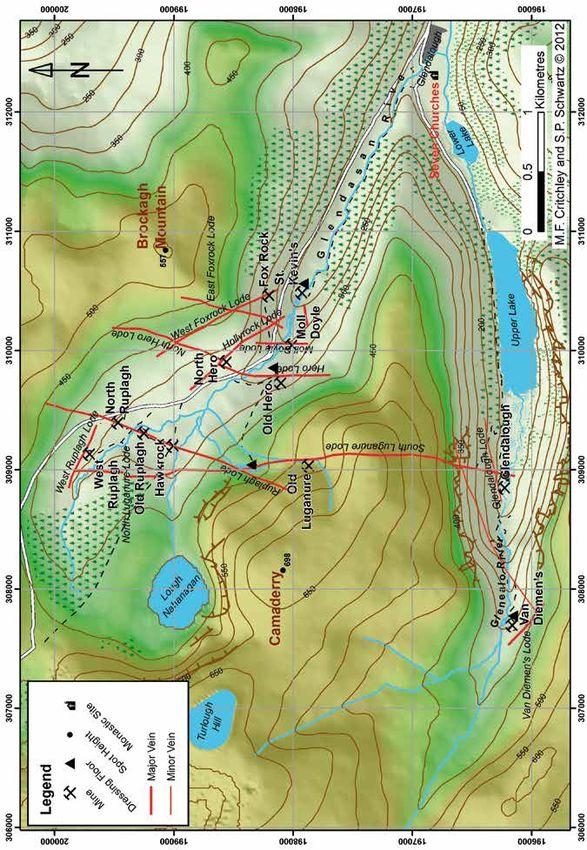
Map 1. The Luganure Mines in the valleys of Glendalough and Glendasan showing the location of the main lodes, mines and dressing floors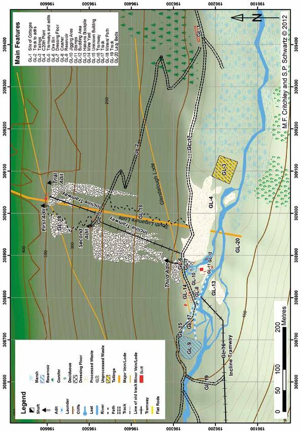
The Lead Ore Dressing Floors at Glendalough and Glendasan, Co. Wicklow 1825-1923

formed a partnership with the Reverend James Symes of                                  The relative success of the MCI’s Luganure mines was largely
Ballyarthur, Ovoca, and John and/or Peter LaTouche of                                  due to the area’s geomorphology, the mineral lodes being
Bellevue, Delgany (and of the Dublin banking dynasty) to                               exposed by the fortuitous effects of glaciation, with the main
sink mines at ‘Glendalough and Shangeen’, with a total                                 lode that ran through Camaderry Mountain for example,
investment of £1,000, each partner holding twenty shares                               accessed via cliff face adits. This meant that fewer deep shafts
(PRO Dublin).2 The Glendalough Mine Company agreed to                                  had to be developed, saving on pumping and winding costs.5
dispose of their possession to the MCI as a going concern and                          The water escaped freely at the mouths of various adits and
all materials, ore on hand and machinery were transferred in                           the lodestuff was cheaply hauled to the surface along tramways,
exchange for 900 shares in the MCI (MC 1825); £4943 5s 4d                              principally by mules, then transported to the valley floors for
was paid by the MCI for the Glendalough Royalty and £2375                              processing. Steam power was therefore not deployed by the
for the mines and materials.3 Over the course of the next six                          MCI at Luganure in contrast to many of their other operations
decades, the MCI thoroughly explored their mineral sett                                in Ireland. Waterpower was recognised early on in major
known collectively as the Luganure Mines, opening workings                             mining areas to be a more effective method of motive power
on lodes in Glendasan, including South Luganure, Ruplagh                               than the use of human or animal power and ‘it undoubtedly
and West Ruplagh, East and West Fox Rock, Hollyrock, Moll                              shaped the landscape and the development of industry
Doyle, Hero and North Hero. In the neighbouring valley of                              throughout the British Isles’ (Watts 2000, 5). In common with
Glendalough, the South Luganure Lode was worked where it                               many lead mines in remote and upland areas of the Pennines,
continued SW from the Glendasan valley and outcropped high                             Derbyshire and Wales, extensive use was made of waterpower
up in the side of the mountain. The Glendalough Lode and                               at the Luganure mines. The water was obtained from the
those at Van Diemen’s Land were also exploited (see Map 1).                            glacial corrie at Lough Nahanagan, source of the Glendasan
                                                                                       River, and the Glenealo River that flowed into the Upper Lake
The mines attained their zenith in the 1850s and 60s. The price                        in Glendalough. This was delivered via a sophisticated
of lead rose sharply in the early 1850s and remained relatively                        network of reservoirs, leats and weirs to power vertical wheels
constant (not experiencing the huge peaks and troughs of                               that could transmit power either through an axle or via a ring
previous decades) until the 1870s. It was during this period                           gear to drive belts or gears for pumping and winding
that the workings on both sides of Camaderry were connected                            machinery, stamping mills and a host of other appliances.
by an adit driven through the mountain. Following a decline in
the price of lead due to the chill wind of foreign competition                         Another major factor in the relative success of the Luganure
from the 1870s onwards, in 1890 the mines and estate of                                mines lay in the fact that the MCI was a large and wealthy
Glendalough were advertised for sale by the MCI and were                               company, able to spread profit and loss across several other
purchased at auction by Mr Wynne of Ballybrophy for £3,450                             mining enterprises in Ireland. A smaller operation would not
(FJ 1890); liquidators were appointed in March 1891 (FJ                                have withstood the vagaries and fluctuations of the nineteenth
1892). The Wynnes, an Irish family of mining engineers and                             century mineral market and periods when the mines proved
entrepreneurs with mining concerns in Central Europe and                               less productive. A detailed history of these and other Wicklow
North Africa, stated their intention to continue mining and that                       mines is being prepared and will appear in a future publication
they did, with varying degrees of success, up until their                              entitled, Mining ‘the Garden of Ireland’: Wicklow’s Metal
company (the Wicklow Mining Company Ltd.) set up in 1900,                              Mines and Mining Communities (Schwartz and Critchley,
was finally removed from the companies register in 1975.4                              forthcoming).
Continually stymied by a lack of capital, workings were on a
smaller scale than during the MCI era. It seems that the                               DRESSING THE LEAD ORE: A HISTORY OF
Wynnes stripped the mines of all merchantable materials such                           NINETEENTH CENTURY METHODS
as waterwheels, stamps, crushers, horse whims, tramways,
wagons, capstans, flat rods and other machinery before WW1,                            Before any ore can be smelted, it has to be dressed to eliminate
hence the reason why there is not a good survival of artefacts                         gangue (waste) material, to remove other uneconomic metallic
from the MCI era. At some contemporary remote Welsh lead                               minerals, separate closely occurring minerals and to reduce it
mines there is good survival of nineteenth century metal                               to a proper size.6 When brought to the surface, broken ore
artefacts, as it was probably not considered worth the cost of                         contains material ranging from large lumps to fine particles,
breaking and transporting these to be sold as scrap. By                                but for successful smelting no lumps larger than about four
contrast, the majority of the metal artefacts on the Luganure                          inches (10cm) were normally permitted and for hydro-
mines date from the Wynne’s mid-twentieth century                                      metallurgical processes, fineness was always necessary,
enterprises, which are not the focus of this paper.                                    sometimes even complete pulverisation (Truscott 1923, 2-4).
                                                                                       The Luganure mines worked low temperature hydrothermal

2 Weaver named ‘an old trial at head of Great Ravine on Luganure Vein’ as
                                                                                       5 There were shafts pumped by flat rods run off water wheels at Old Hero,
well as an ‘old drift’ (located above First Adit) on a plan dated 1814, strongly
                                                                                       North Mine, Hawk Rock and Moll Doyle (Glendasan) and Ennis’ Shaft (Van
suggesting that these workings predate his activity in the valley and are thus
                                                                                       Diemen’s Land), while horse whims were also used on some of the shafts.
eighteenth century or earlier in derivation.
                                                                                       6 Also of importance is the regular character of the lead concentrate passing
3 Terms vary. The MCI report of 1825 states that they had bought out an un-
                                                                                       through a particular dressing floor that was supplied to a smelter. The
named company for £826 /4/3, 798 shares, 30 tons of ore and mine materials.
                                                                                       regular mechanical and chemical nature of the concentrate meant that in the
4 The St Kevin’s Lead and Zinc Company that mined Foxrock in the late                  provision of flux, the margin of safety could be substantially reduced and the
1950s was a Canadian subsidiary of the Wicklow Mining Company Ltd.                     charges therefore made up more economically.

                                                                                   7
Journal of the Mining Heritage Trust of Ireland No. 12

lode deposits that formed in fractures in the host rocks                          the ore, the basic mechanism for separating the ore from its
(granite) by crystallisation from metal-rich brines during the                    waste matrix or ‘gangue’ was universal: the gradual reduction
late phase emplacement of the granite. The most common lead                       of the ore into particles of similar size which could be washed
bearing mineral is galena7 (lead sulphide), bound up primarily                    or settled out in water according to their specific gravity. For
in a quartz gangue, and there are varying quantities of                           galena this was 7.2-7.7 and for quartz, 2.5-2.8. The process
sphalerite (zinc sulphide) and chalcopyrite (copper sulphide)                     could not be achieved in one simple stage, hence the different
present in the two valleys (see Moreton and Green 2007 for                        apparatus for settling out the ore from its gangue in various
details of the supergene minerals present).                                       successive settling operations. Key to successful concentration
                                                                                  was not to grind brittle ores like copper and lead too finely at
The Luganure lead ore is also argentiferous, Jukes and Noyer                      the very start of the process, for two reasons. Firstly, irregular
(1869) noting that the galena from the Luganure Lode yielded                      sized particles prevented separation by specific gravity,
about 11 oz of silver per ton after dressing, although a sample                   meaning a lot of fines escaped. Secondly, the treatment of
of the Mineral Statistics for 1862 and 1867 only indicate 6-7                     fines required more labour and time and hence was more
oz per ton of concentrates. This was not particularly rich, as                    costly, thereby reducing profit margins. Throughout the
Kilbricken (County Clare) ores contained 120 oz per ton and                       nineteenth century, ways were sought to improve the efficiency
Shallee (County Tipperary) 25 oz per ton (Homans 1860,                            of ore dressing to eliminate waste, speed up throughput, save
1090). Indeed, dressed ore containing over 30 oz of silver per                    labour and increase profitability. Many improvements resulted
ton, or about 0.1%, was considered valuable (Hall 1921, 3).                       from the introduction of innovative machinery.
The silver in the Luganure galena may present itself as
isomorphus sulphide (Ag2S) within the crystalline matrix of                       There are numerous extant dressing floors situated on the
galena, or a discrete silver-bearing mineral such as argentite,                   Luganure mines dating from the nineteenth century. Several of
stephanite or native silver. In the former case, the loss of silver               these are shaft head primary dressing floors consisting of little
in the dressing process is proportionate to the loss of lead, but                 more than a rectangular cobbled area, used for the initial
in the latter, the loss of silver greatly exceeds that of lead as it              sorting of ore to avoid the cost of transporting useless ‘gangue’
is finer to begin with and much lighter and more brittle, so that                 (waste) materials to the main dressing floors. Excellent
it is driven into the finest slime and easily carried away on the                 examples survive at Van Diemen’s Land, Harold’s Shaft
surface of water. Silver was extracted at the Ballycorus                          (North Hero) and Bog Shaft (West Ruplagh). During the
smelting works near Dublin (Normoyle 2006) by the Pattison                        nineteenth century, two main dressing floors served the
Process.8 Ore from disseminated lead deposits may contain as                      Luganure mines: one at Old Hero (Glendasan) dating from the
little as 3-4 per cent of lead, but smelting was rarely                           late-1820s-early 1830s and another constructed between the
                                                                                  Upper Lake and the head of the Glendalough valley in the
undertaken upon material containing 10 per cent or less
                                                                                  mid-1850s.
metallic lead, as this would not permit the proper collection of
the silver generally present. Although it is difficult to ascertain
                                                                                  In order to prepare it for smelting, the ore passed through five
the lead content acceptable to nineteenth century smelters as
                                                                                  general phases of treatment which are detailed below.
marketing conditions varied enormously, reverberatory
furnaces commonly processed lead concentrate with a metallic
                                                                                  1) Sorting. Lodestuff was roughly sorted underground by the
content averaging 40-60 per cent and occasionally demanded
                                                                                  tributers who had mined it to avoid having to transport
that this be over 70 per cent (Truscott 1923, 2-4). Concentrate
                                                                                  unwanted gangue materials to the surface. Although this task
averaging 60-75 per cent metal was processed at the MCI’s
                                                                                  was performed by candle light, tributers were very adept at
Ballycorus smelter in the years 1850-1880 (calculated from
                                                                                  selecting only the best ore (often by judging its weight) as they
the Mineral Statistics).9
                                                                                  usually had to pay for its transport to the surface either via
                                                                                  kibble up a shaft, or by tram to an adit mouth. Deads were
It is impossible to understand or to interpret the form and                       stacked onto platforms in stoped out sections of the mine. On
function of nineteenth century dressing floors with little or                     many lead mines the mined ore when brought to the surface
limited knowledge of ore dressing techniques or the machinery                     was stored in a ‘bouse team’ (from ‘bouse’ the northern
employed. This section therefore provides a brief synopsis of                     England dialect word for ore), also known as an ore bin or
the main methods of nineteenth century lead ore dressing and                      hopper, prior to being washed.
discusses most of the key types of equipment that were in use
at British and Irish mines. Although regional differences                         2) Washing. The ore fragments had to be cleansed of mud to
occurred in the type and layout of machinery used for dressing                    reveal the ore before any processing could commence. On
                                                                                  arrival at the surface the very largest lumps of ore were
7 Galena is often well crystallised and freshly cleaved specimens exhibit a       usually ‘ragged’ by use of a 10 lb sledge hammer to reduce
strong metallic lustre, which tarnishes over time.                                them in size. The next stage of the operation was termed
8 The Pattison process extracted silver by crystallisation at a different         ‘grating’ which washed, sized and sorted the ore. In its crudest
temperature than lead. It was only the fact that the MCI was mining large         fashion, this was achieved by use of a series of riddles (large
tonnages of lead at their Wicklow mines that made it worthwhile to process
the fines and to extract the silver at the smelter (FJ 1853) and in 1859 it
                                                                                  sieves with various sized meshes) into which the ore was
was reported to the MCI shareholders that the extraction of silver at the         placed and then agitated violently in water to separate the ore
Ballycorus works was ‘a very valuable adjunct to the Luganure Mines’ (FJ          from the gangue and to size it. Ore dressers soon became very
1859)                                                                             adept at picking out the valuable mineral by its specific colour,
9 Galena (lead sulphide) contains no more than 86 per cent metallic lead.         lustre, appearance and weight. ‘Prills’ (lumps) of pure galena
                                                                              8
The Lead Ore Dressing Floors at Glendalough and Glendasan, Co. Wicklow 1825-1923

                               Figure 1. Grating lead ore in the North-East Pennines c.1805-1820.
                                   Reproduced with kind permission of the Science Museum

were easily separated on the sieves, crushed to a proper size             The largest pieces of mixed ore requiring reduction were sent
and ‘sent to pile’ (ready for smelting). Larger pieces were               to the spallers and cobbers, the gangue fragments thrown
washed in a rectangular buddle, a simple declivity in the                 away, the prills ‘sent to pile’ (ready for smelting) and the
ground and the metalliferous mud was caught in a slime or                 contents of the pit and smaller fragments of mixed ore were
‘slitch’ pit for settling out and further treatment. After grating,       sent to the crusher. Later, this first stage of the dressing
the ores would have been sorted into four lots:                           process was mechanised by the introduction of a wash kiln
                                                                          that included a built in trommel (see below) to classify the ore.
    •    ‘deads’ containing little or no ore that was thrown              These were highly popular on smaller Welsh lead mines and
         away on spoil heaps                                              ensured a rapid and more even through put and processing of
    •    ‘drage’, ore mixed with gangue that required hand                ore.
         sorting
    •    ‘halvans’, poorer ore that required crushing                     3) Reduction. Prior to mechanisation, hand labour was
    •    ‘prills’, pure lumps of ore requiring no further                 employed on ‘drage’ by ‘spalling’ ‘cobbing’ and ‘bucking’
         processing                                                       (terms acquired from the Cornish mines) undertaken on a flat
                                                                          dressing area that was cobbled to provide a firm striking
On some mines in Britain, such as those in Cardiganshire                  surface; the extensive cobbled dressing floors at the South
(Ceredigion), Wales, the washing of the ore became a fully                Caradon copper mine in Cornwall are an excellent example.
integrated part of the ‘bouse team’ (Palmer and Neaverson                 Spalling was undertaken using a 6 lb sledge hammer to reduce
1989) with a large grate of parallel iron bars spaced about half          the ore to fist sized lumps. These were then cobbed, using a
an inch apart located directly below it, at the end of which was          chisel edged hammer weighing some 3 lbs to chip the ore
a wooden board or slide (Figure 1). The ore was washed in a               away from its waste matrix on an anvil. ‘Bucking’, performed
strong current of water and raked over on the grate. Small                with a flat headed square hammer on an anvil or ‘buck stone’,
fragments fell through into a pit below and the remainder was             reduced the ore to a gravel like consistency ready for
drawn onto the picking board and sorted (Forster 1883, 175).              classification. Depending on the mineral being processed, the
                                                                      9
Journal of the Mining Heritage Trust of Ireland No. 12

         Figure 2. Cornish rolls crusher accommodated in a two storey house similar in design to those installed at
  the Luganure Mines. Note the triangular ore hopper in the top storey, the trommel in the bottom storey (left) and weights
                              suspended outside the building to provide tension for the rollers

reduction process could have been completely mechanised by                     The apparatus consisted of a pair of iron cylinders sheathed
means of a stone breaker, rolls crusher and stamps.                            with chilled cast iron ‘tyres’ placed horizontally and nearly in
                                                                               contact and that were connected together by spur wheels of
The stone breaker was invented in the United States in 1858                    equal diameter, so that surfaces revolved towards each other
by Eli W. Blake. Lodestuff was fed into a crushing hopper and                  with equal velocities. In earlier models, the two wheels were
broken between a pair of iron jaws, one being fixed, the other                 not geared together and motion was given to just one of the
actuated by knee-joint levers, to the size of road-metal. The                  rollers, either by steam or waterwheel, allowing it to be moved
jaws were operated by a belt drive powered by a waterwheel                     round by the friction of the material against it. Experience
or steam engine. The rolls crusher were the brainchild of                      proved it was better to gear both rollers and in later designs,
mining doyen, John Taylor. In 1796 he built an improvised set                  one roll revolved in fixed bearings, the other in a moveable
at Wheal Friendship, near Tavistock in Devon, on an occasion                   bearing-and-bracket assembly held in position by compression
when the surface workers struck and in 1806 an improved                        (Lynch and Rowland 2005, 60). The diameter of the rolls
version was installed at nearby Wheal Crowndale (Collins                       varied from 13-34-inch and the length or breadth of face from
1912, 268). Dubbed ‘Cornish rolls’, this type of crusher soon                  12-24-inch (Lock 1890, 314). In the early models weights
found its way on to numerous mines in Cornwall and                             regulated pressure and thus controlled the size of the crushed
elsewhere, superseding the upright cylinder stone crushers                     material passing through the rollers and were suspended on
known in the Americas as ‘Chilean mills’ that were, for                        the end of long levers that often projected outside the building
example, widely employed on the Peak District mines. These                     through slots in the wall, while some designs accommodated
consisted of a large stone pivoted by a horizontal axle to a                   the weights inside the house; later models used springs to
rotating vertical wooden centre post drawn around by human                     regulate pressure on the rolls.
or animal power, the ore to be crushed laid in the path of the
stone (Burt 1982, 21). Cornish rolls performed medium sized                    Ore was fed into a hopper in the upper storey where it fell
crushing and were very effective on brittle minerals like lead                 through onto the rolls to be crushed to a fine gravel and then
and copper; importantly, they replaced the need for bucking, a                 passed into an inclined revolving cylindrical sieve named a
largely female task, and were thus labour saving.10. They                      trommel, sited below the rolls on the lower storey. The finer
required about 10-20 hp and could handle about 4-8 tons of                     fragments of ore passed through the screen of the trommel, but
stuff per hour (Truscott 1923, 57). Those powered by a                         fragments not crushed small enough passed along the trommel
waterwheel were usually accommodated in a two or three                         to be lifted up via a Raff wheel into the hopper again to be
storied building, sturdily built to resist the vibrations of the               re-crushed. The early crushers could only process lodestuff
machinery (Figure 2).                                                          already reduced by hand labour/stone breaker and much larger
                                                                               machines with multiple rollers were later devised to ensure a
                                                                               more efficient through-put of ore and a more evenly sized
10 They were initially resisted on many Cornish mines for putting women        product able to process the lodestuff direct from the washing
out of work (Schwartz 2000).                                                   floor. Cornish rolls came to be regarded as the best constructed
                                                                          10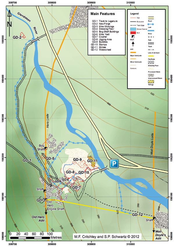
The Lead Ore Dressing Floors at Glendalough and Glendasan, Co. Wicklow 1825-1923

         Figure 3. A six-head double battery of water powered Cornish stamps manufactured by Harvey's of Hayle,
                             Cornwall, similar in design to those in use at the Luganure Mines

and the most efficient in operation and resulted in the least          heavy framework of wood. The heads normally weighed
fines to be lost during subsequent treatment.                          between 200-300 kg each, were commonly arranged in sets of
                                                                       4-6 and each head could deliver 50-60 blows per minute,
Cornish stamps (Figure 3) were widely employed on British              although 40-50 was more common. Fixed to the upper part of
tin mines where the finely disseminated cassiterite had to be          the stem was a ‘tappet’ which engaged a ‘cam’ attached to a
pulverised to liberate it from its gangue matrix and on copper         horizontal shaft or ‘barrel’ powered by a water wheel (five
mines where the ore was bound up in hard quartz gangue, but            cams per stamp head). As the barrel rotated, the cam lifted the
they were less common on lead mines. In 1778 it was                    stem upward (via the tappet); as the cam disengaged the stem
recommended that lead ore ought to be ‘bucked and jigged,              and head fell back under its own weight to pulverise the ore
and very seldom carried to the strêke, or stamps, except when          placed beneath. Cam-lifted stamps were limited by the speed
it be very scarce and thin in the stone; but when it is so poor        at which they could run, but were well suited to water power.
as to make bucking and jigging improper and costly, then it is         The ore was fed into the ‘mortar’, essentially a box into which
scarce worth the trouble of stamping…’ (Pryce 1778, 243).              a flow of water was directed and which had an opening at the
Stamps were mainly used in the nineteenth century for                  back to receive the ore. This was passed from a hopper above
crushing ‘halvans’ or poorer ores and the ‘chats’ from jigging         down an inclined plane of wooden planks. The mortar box had
operations. Among nineteenth century lead mines in Cornwall            a perforated metal screen at the front. This specially fabricated
and Devon using stamps were East Tamar, Herodsfoot, New                metal screen was of sheet iron (sometimes copper) in which a
Crow Hill, Redmoor, Tamar Silver Lead Mine, Wheal                      series of holes were punched and which was held in a plate of
Exmouth, Wheal Mary Ann, Wheal Penrose and Wheal                       cast iron with a central rectangular opening for the screen
Trelawney. Some of the Cardiganshire mines also employed               which could be replaced once worn away by the action of
stamps for the same purpose, for example the John Taylor run           sands or acid water. The size of the screen varied and was
Frongoch and Goginan mines and they were also used at his              dependent on the type of ore being processed and how fine it
Grassington mine in Yorkshire. The London Lead Company                 was to be pulverised. The perforations for lead stamping were
sometimes used stamps for dressing ore in addition to                  generally larger than those for copper and certainly much
re-treating slags at smelting mills. Ure (1866, 41) notes that         larger than for tin, the holes of which were usually less than 1
those around Alston Moor were water powered. However,                  mm in diameter (Moissenet 1858, 83-84). As the ore was
many of the large lead mines in the north of England relied on         pulverised, particles of ground ore splashed against the
Cornish rolls for re-crushing rather than stamps, such as the          perforated screen which in effect sieved them.
Derwent Mines but also the Laxey Mine in the Isle of Man.
                                                                       The muddy sands passed out through the perforated screen
The Cornish stamps comprised a number of huge pestles or               down a discharge plank (a board down which the stamped
‘stems’ of wood with iron heads supported vertically in a              material ran to be deposited according to its specific gravity in
                                                                  11
Journal of the Mining Heritage Trust of Ireland No. 12

strips or sometimes a dumb buddle). Depending on the nature               5) Concentration. Separation and concentration of classified
of the ground, the base of the mortar boxes were constructed              larger fragments of lodestuff was effected by ‘jigging’, while
of fragments of very hard quartzose schist of various sizes               the finer materials were treated in a variety of buddles. These
with finer gravel on top which was packed within a square                 processes were highly labour intensive during the nineteenth
wooden frame. Upon installation, stamping was undertaken                  century and many were gradually mechanised to speed up
for some four to five hours using killas (metamorphosed                   through-put, save labour and eliminate waste. Crushed ore
slates) which turned to a clay like substance filling the voids           was jigged to enable pieces of ore and gangue to be
between the quartzose fragments. Iron fillings and urine were             successfully separated by maximising the differences in
sometimes added to the clay like mixture to bind the whole                specific gravity. The crudest and cheapest form of jigging was
together to form a permanent solid base for the stamp heads.              by using a hand held sieve similar to that used for sizing.
                                                                          Made of a circular hoop of oak with a wire mesh bottom, these
4) Classification. This was necessary to sort the ore into                measured 18-20 inches in diameter and were about 6 inches
particles of similar size which could be washed or settled out            deep. The sieve was filled with a mixture of lodestuff and then
in water according to their specific gravity. Methods of                  violently agitated in water, held either in a tub or a simple vat
classification remained fairly primitive throughout the                   in the ground. The heavier pieces of ore accumulated in the
nineteenth century (Palmer and Neaverson 1989, 24). The                   bottom of the sieve, the mixed ore and gangue in the middle
largest particles of ore (1.4 mm to around 50 mm) could be                and the sterile upper layer of quartz gangue rose to the top.
graded relatively easily using simple sieving techniques.                 The sieve was periodically lifted out of the water and the
However, smaller sands and slimes, resisting such simple                  gangue scraped off with a ‘limp’ (a half moon shaped iron
sieving techniques, required complex classifying devices on               shovel). The middle layer invariably contained small bits of
the principle of differential suspension in water.                        galena mixed with gangue and so they were either put aside
                                                                          for further crushing, either by hand or in a stamping mill and
Manual methods of classifying large crushed material included             then reclassified.
the use of flat bottomed sieves and a trommel. The former,
simple hand held circular sieves known as ‘riddles’, were                 The succeeding separation was again conducted in the jig or
18-20 inches wide and 6 inches deep with variable sized                   in a buddle, depending on the size of the material obtained.
meshes of copper or iron wire held together by a hoop of oak.             The concentration of fat ore in the bottom of the sieve could
These enabled the crudest method of classification and were               be removed, but often it was left in the sieve and mixed slimes
in use throughout the nineteenth century, especially on smaller           that had fallen through the sieve and collected in the drained
mines. Riddles were later replaced by flat sieves mounted in a            vat were scooped onto the top layer of ore in the sieve. The vat
vertical series and operated by a central rod on larger mines.            was filled with fresh water and the layer of ore acted as a filter,
More common was the revolving trommel, usually constructed                allowing only the heaviest metalliferous particles to pass
of perforated iron or copper sheet. At first these were hand              through into the vat. The gangue was trapped at the top
operated and of a single gauge, the lodestuff being carried               allowing it to be removed with a limp. This was either thrown
from one to another of these devices with a finer screen. These           away as waste, or sent as ‘buddler’s offal’ for further washing,
simple hand operated devices were very well suited for the                while the heaviest particles that had sunk to the bottom of the
preliminary sizing of coarser ground copper and lead ores.                vat were processed by buddling. Water and metalliferous
Later trommels were mechanised and contained mesh of                      sludge was swirled round to encourage the lighter particles to
various sizes to classify the lodestuff and could be up to                rise to the top where they could be tipped away or sent for
twenty feet in length.                                                    further processing in a buddle.

The simplest method to classify finely crushed material was in            This application was the precursor to the kieve or ‘dolly tub’,
a series of classifying pits of increasing dimensions and                 a deep cylindrical wooden tub some three feet eight inches in
decreasing inclination on an almost horizontal floor. Water
flowed rapidly through the first pit and then, by a process of
overspill passed more slowly into succeeding pits which
increased in size. The coarser, heavy grained stuff was
deposited in the first pit and the lighter material was carried to
succeeding pits where the rate of flow and agitation of the
water was reduced. A further degree of separation was
achieved within each pit as the heavier metallic particles sank
to the bottom while the sludge and the lighter gangue remained
on top. Classification pits had their drawbacks, as they were
very labour intensive, took up a lot of space and they had to
be periodically stopped to drain them and dig out the
accumulated stuff, causing an interruption to the crushing
operations. Yet, some smaller British lead mines continued to
use a system of settling tanks well into the late nineteenth
century. Labour and space saving fine classifiers such as the
                                                                              Figure 4. A mechanised kieve or 'dolly tub' used for
partially mechanised pyramidal trough and cone classifiers
                                                                                           concentrating fine slimes
were later refinements.
                                                                     12
The Lead Ore Dressing Floors at Glendalough and Glendasan, Co. Wicklow 1825-1923

   Figure 5. A hand operated brake jig. The brake jig was operated by a wooden lever (A) having its axis at (F). A piece of
   wrought iron (B) is attached to the end of lever (A) and its upper end passes freely through a slot opening in lever (D)
   with two shoulder projections (C). (E) is the axis of lever (D) and (G) the framework connected with it and that support
     the iron rods (H) attached to the rectangular sieve (J). (K) is the hutch or tub which forms the cistern for the sieve,
   from which a chute (L) for the overflow water protrudes. The fines are collected in a slitch pit (M) as well as receiving
                ore from the hutch. The apparatus was set in motion by simply jerking lever (A) up and down

diameter that was used to re-treat the finest slimes from jigs or          was suspended above a tub of water (Figure 5). Reconstructed
buddles by a process known as ‘tozing’ (tossing). The kieve                examples can be seen at the Killhope lead mine in the North
was almost half filled with water and shovelfuls of material               Pennines and the Minera lead mine at Wrexham, Wales. The
were slowly introduced down either side. The contents were                 operator simply jerked the lever up and down to immerse the
constantly stirred with a shovel in a circular motion until the            sieve in the water. Clean water entered the bottom of the hutch
water rose to within around two inches of the top of the tub.              via a square pipe and momentarily lifted the particles of ore
The contents were then ‘packed’, a simple process which took               and gangue, while the muddy waste was carried off through a
anywhere between 15 minutes to one hour whereby the side of                similar pipe fitted with discharging apertures at the opposite
the kieve was steadily thumped by an iron bumping-bar to aid               side of the tub (Lock 1890, 340). Small fragments of galena
the subsidence of the heavier metalliferous particles. When                fell through the sieve, the larger prices becoming trapped on
the packing was completed, the water was siphoned off into a               the mesh, while the lighter gangue rose to the top allowing a
nearby kieve, the top sand skimmed off and sent to be buddled              workman to skim this off with a ‘limp’. The top skimmings
and the fat ore that had sunk to the bottom shovelled out and              were discarded to the spoil heaps, the middle skimmings
sent to pile for smelting. Kieves were easily mechanised by                containing mixed ore and gangue were left on the sieve with
installing a central vertical shaft with stirring blades like those        the crop ore and were re-jigged with a charge of new material.
of a propeller at the bottom, operated by a crankshaft run from            The process was continued until sufficient separation of the
a waterwheel or engine (Figure 4). Wooden mallets worked by                ore from the gangue was made. The middlings or ‘chats’, were
machinery driven by water or steam power were also installed               sent to the stamps, the crop ore sent to pile and the
to speed up the packing process and to obviate the need for                metalliferous slimes that collected in the jigging tubs were dug
manual labour (Henderson 1858).                                            out and, if rich enough, sent to pile, or if not sufficiently
                                                                           cleansed of impurities, treated by buddles. The fines carried
Jigging boxes or ‘hutches’ were of many different designs,                 off in the discharge water were settled out in tanks.
introduced to maintain a constant through-put of ore and were
the main method of separating those ores that were less finely             The first mechanised brake jiggers were introduced at the
reduced, such as lead and copper. They operated on the simple              Duke of Devonshire’s Grassington Moor lead mine in
law that when two bodies of equal volume and of different                  Yorkshire by Cornishman, Captain John Barratt. These were
specific gravities are dropped at the same instant from the                worked by a small waterwheel and were deemed more
same height into a volume of water, the one of the greater                 efficient in terms of labour and quality of ore obtained than
weight will sink faster than the other, leaving it behind, and             that achieved by manual operations. Their introduction marked
arriving first at the bottom (Davies 1902, 291). The simplest              the rapid diffusion of the mechanical sieve and trommel
design, the brake jig, comprised the traditional hand sieve in a           classifiers to feed the jigs with accurately classified material.
square wooden frame attached to a simple overhead lever                    In 1828, Captain Thomas Petherick of Fowey Consols Mine in
mounted on two fixed supports on either side of the sieve that             Cornwall (Lewis 1997, 38-41), set about developing a
                                                                      13
Journal of the Mining Heritage Trust of Ireland No. 12

mechanised hydraulic jig (QMR 1832; SM, 1834). ‘Petherick’s
Separator’ kept the sieve stationary but moved the water up
and down in the hutch by means of a plunger operated by a rod
activated by a rocking beam run by a crank on a flywheel that
was easily driven by a waterwheel. The hutch was filled with
water to a point just below a lid that covered it and that
contained circular holes to accommodate up to eight sieves
filled with material to be dressed; the bottom of the sieve was
suspended just above water level (Hunt 1864, 852-3). The
sieves were simply replaced when layered, a less arduous task
for the boys previously employed at manual hutches. Petherick
patented his Separator in 1830 (with a further patent following
                                                                           Figure 6. The tye was often used for cleaning hutchwork.
modifications in 1832) that produced a higher quality product
                                                                          An inflow of water (A) flows into the head of the tye (B) and
at a reduced labour cost (Penny Cyclopaedia 1839, 245). It is
                                                                          down over a partition board (C). The stuff is introduced into
tantalising to speculate that the MCI might have used
                                                                          a cistern (D) and flows down over the inclined front (E) and
‘Petherick’s hutches’ at their mines, as he was the elder
                                                                          is agitated by a broom (F). Heads are deposited between (E)
brother of John and William, both MCI mine captains. Later
                                                                            and (G), middlings from (G) to (H) and the tailings at (I)
inventions included continual jiggers which built on the
design of Petherick’s separator making use of multiple sieves
of different mesh, but all continued to employ the basic
techniques first developed in the manual jigging hutch.                   A running or nicking buddle was somewhat similar in design
Further modifications and improvements resulted in later                  to the lower half of the trunking buddle, the main differences
pneumatic jigging hutches in which pulses of water were                   being that a trunking buddle employed a slightly inclined
generated by compressed air.                                              board at the head of the trough making it easier to brush or
                                                                          rake the ore against the flow of water and the running buddle
Buddles, an ancient device used to concentrate sands and                  had no pit, but was set into the ground and lined with a stone
metalliferous slimes by using the difference in specific gravity          or wooden floor. The running buddle was used to further
of ore and gangue, retained their popularity as a relatively              concentrate the clean ore from the trunking process; by
cheap and effective method of concentration throughout the                reworking the various grades of material several times by
nineteenth century at most lead mines in Britain and Ireland.             brushing the material against the current of water, a very
Buddles came in a variety of shapes and forms, but one of the             effective cleaning of the ore was effected with little loss of ore
most common was the trunking or square buddle (also known                 with the gangue. Most large mines would have employed
as the hand buddle), reputed to be one of the most effective of           separate running buddles so the trunking buddles could be
all the early buddles. It was a rectangular box of varying                kept fully employed.
dimensions and capacity sunk below ground level, with the
lower side being flush with the surface, the floor having a               Tyes comprised a large wooden channel which incorporated a
definite slope. A hopper was erected at the top end into which            strong head of water (Figure 6). Into this flow a workman
material was thrown by shovel and constantly washed out by                slowly added shovelfuls of material. The heavy particles
a strong stream of water on to a triangular inclined plane fitted         settled at the head of the channel and deposition was aided by
with strips in a fan-shape that distributed the material. The             working the material with a shovel or broom. A box that was
spaces between the strips acted as channels where the feed                deeper and larger than the wooden channel caused the material
material split up and formed a flowing coating, the same width            to slow down which aided separation of the ore. A workman
as the buddle. This was then evenly distributed by falling on             constantly agitated the material in the box, periodically
to a small, narrow sloping board the same width as the buddle.            removing the roughs (poor coarse sands) that were retreated in
                                                                          a separate channel. Gangue and slimes were carried to the tail
Alternatively, a large ‘jagging’ board was placed at the head of          of the tye and run off into slime pits. These tanks, usually
the buddle onto which sands were placed directly and down                 rectangular in shape, were about 8-10 yards long, one yard in
over which water was directed. An ore dresser would constantly            breadth and about 2-3 feet deep. At one end, a small opening
make small channels, parallel to the axis of the buddle, in the           close to the top allowed the water to discharge and the heavier
material with the edge of his shovel to aid flow and distribution.        slime to settle in the bottom. When one tank was full, the
A boy was also employed to work the buddle to ensure that the             muddy water was turned into the other one and the accumulated
deposits formed a level inclined plane, usually with the aid of           material dug out and sent to the buddles for separation (Forster
a long handled broom. Material was divided into the head,                 1883, 177). Tyes were gradually replaced by round buddles.
fore-middle head, hind middle head and tail (Henderson
1858). The water carrying fine slimes escaped from the lower              Strips were commonly used to treat the sands coming off the
end of the buddle through holes pierced in the ‘tailboard’ a              Cornish stamps. Along the front of the stamp battery was
wooden partition which formed the foot of the buddle. Plugs               planking about one metre wide, laid either perpendicular or
were placed in these holes in the tailboard as the level of               parallel to the stamps axle. The stamped material ran off into
deposited material grew. An underground launder carried                   these strips, one half of which received material while the
away the waste water (Moussinet 1858, 28). The rich heads                 other half was dug out. Movable stops fed the sands
were usually sent to kieves for tozing.                                   alternatively to each half. Some of the strips were uniform in
                                                                     14
The Lead Ore Dressing Floors at Glendalough and Glendasan, Co. Wicklow 1825-1923
length (about 10 metres) while some were interrupted by a
couple of drops in height to produce an effect of several strips
laid end to end. At the lowest end, vertical partitions containing
two slots into which a cross piece was placed created a
moveable stop that raised the level of deposited material in the
strip. Water and slimes ran over the top of this and were
channelled into a launder and run into a slimes pit. The strips
separated out material into three broad grades: crop sands or
‘heads’ of fine enriched material; ‘middlings’ that were less
rich, and ‘tails’, larger grained material often mixed with
slimes. Crop sands from the strips sometimes passed directly
to a square buddle for further processing. Alternatively, the
three different grades of sands could be treated in round
buddles and there were often three of these to allow for the
rotating of treatments (Mouissenet 1858, 29).
Figure 7. A convex circular buddle used for concentrating
sands
Mechanisation of the trunking buddle came early in the
nineteenth century with the introduction of the knife and then
ranging from fourteen feet to twenty five feet.
impeller buddles. These were fitted with paddles and knives
often powered by a crank run off a stamps waterwheel, or by
The concave buddle was often used to concentrate the heads
an independent waterwheel. Knife buddles were employed in
from convex buddles or very fine ore mixed with considerable
many of the Welsh lead mines. In the impeller buddle, a
amounts of gangue. The main difference between a convex
rotating cylinder with projecting blades was placed obliquely
and a concave buddle was that in the latter the conical table
across the buddle board which was slightly curved to
accommodate the rotating action of the knives. As the material sloped upwards from the centre to the sides and material was
fed in at one end gradually traversed the length of the board discharged by pipes around the circumference of the buddle.
by the propelling action of the knives, a highly efficient Revolving brushes prevented water channels forming and the
separation of the ore was effected. stuff flowed evenly towards the centre to a discharge point.
The speed of the material increased towards the centre and this
Mechanised circular buddles marked a new approach to apparatus was therefore considered better at carrying away
dressing sands and slimes. They were particularly prevalent large amounts of lighter gangue. Round buddles were far more
on Cornish tin mines where the lodestuff was finely pulverised efficient than square buddles in that they were virtually self
to release the cassiterite. Insufficiently washed ore was mixed acting and thus labour saving.
with water and fed onto a convex buddle, one of the most
common types of buddle also known as a ‘centre head’ buddle, The round frame, the bowl of which rotated, was invented in
so-called because it had a centre cone of wood or cast iron that Germany in the eighteenth century and much improved in
supported a bearing that turned a vertical iron shaft powered Cornwall and the NE of England. It was a free standing piece
by a drive shaft run from a stamps waterwheel or steam engine of equipment constructed of wood and either concave, with
(Figure 7). The ore slurry was fed in at the centre of the buddle the bed sloping inward from the periphery, or convex, with the
via a wooden launder to a sheet metal box with sides that bed sloping outward from the centre. Both types were
reached just below the top of the central cone. The box had a supported on an umbrella framework radiating from a central
series of perforations in its base through which the slurry spindle that powered the device, generally from a worm drive
passed onto the sloping surface of the buddle. Known from at from above but often by bevel gearing, and did not require a
least the 1820s, these circular pits employed rotating brushes great deal of power which could have been generated by water
(often made of heather) suspended by cords attached to two or steam. The ore pulp was distributed via an annular
wooden arms anchored into two metal crosspieces projecting peripheral launder to about 75 per cent of the deck that
from the feed box. The brushes spread the ore to avoid revolved at about 15 revolutions per hour. As the pulp flowed
channels being formed by the flowing water and moved at across the deck, the heaviest particles settled whilst the lighter
right angles to the run of the water, which was radially down material was carried to an annular tailings launder. Brushes
slope. The brooms were gradually raised as the buddle filled were employed to ensure an even distribution of the material
up. Gravity graded the slurry, leaving the heavier and richest but small jets of water were used to separate the different
ore nearest the centre. Surplus water flowed out of the buddle grades of deposited material. The whole process was
through a vertical slot in the outer rim containing a button hole continuous with a capacity to treat between 5 and 10 tonnes of
launder that led to channels for the discharge of excess water. fine ore a day, grading it into three fractions: heads, middlings
When the buddle was full of sediment, it was emptied by hand and tails, which were discharged into separate launders.
digging in concentric sections: the ore concentrate lying Dressing operations therefore did not need to be interrupted
nearest the centre sent to pile, the waste at the outer while a buddle was dug out, thus ensuring a more efficient
circumference discarded and the mixed grades between throughput of ore. Round frames saved on labour costs, took
reworked. Early examples had cobbles or wooden decking in up less space and much less ore went to waste.
the pit and later built ones were cement faced on concrete. The
finer the sand/slimes, the larger the buddle was, with the sizes Other mechanised versions of concentrating sands and slimes
15Journal of the Mining Heritage Trust of Ireland No. 12
included shaking tables and the frue vanner that steadily began adhering to the belt was deposited into a box containing water
to replace buddles and round frames. By the mid-twentieth as it travelled over the top roller.
century shaking tables had largely replaced vanners, to
become the preferred method for the gravity separation of fine Additionally, numerous specialised devices were developed in
sands. The application of a repetitive ‘bump’ to a bed of ore the nineteenth century to recover slimes from settling pits,
particles and water on a sloping surface, as an aid to separation including slime trunks, rag and hand frames, machine frames
and retention, was well established on German lead and and slime frames that operated on the same principles as jigs
copper mines in the very early nineteenth century. Shaking and buddles. These proved very successful on tin and lead
tables were also in use on British lead mines from at least the mines in particular, where the ore could be concentrated to a
mid-nineteenth century and probably earlier, for example, high level. One such item of equipment was the rack or rag
they were introduced at the Tamar Silver-Lead Mine (also frame, a simple device which had the added bonus of not
known as Tamar Consols), Bere Alston, Devon, in May 1844 being labour intensive, with one boy able to watch over 20
by Percival Norton Johnson and at Treweatha lead mine, near such frames. A launder bringing the slimes from the buddles
Menheniot, Cornwall, in the 1860’s. The first tables were passed between two rows of the slime frames, set back to
actually imported from Germany, but a model was known to back, and the delivery to each frame was distributed by a
have existed in the Royal Geological Society of Cornwall’s fluted spreader that flowed uniformly in a gentle stream over
Museum at Penzance in 1824, and possibly even in 1816 the surface of an inclined frame that was divided at the middle
(Schwartz 2000, 95). An early type of ‘bumping table’ was into two halves by a 5-inch step; the waste flowed off at the
also reported as being designed by Robert Stagg and in use at bottom of the frame into a launder. The stuff deposited on the
the Nenthead lead mines in 1828. But the design of the first frame was then flushed off at successive intervals of a few
continuously operating shaking table, in 1857, is widely minutes each, by a self-acting contrivance consisting of two
credited to the pioneering Austrian mineral processor, Peter rocking troughs which were gradually filled with clear water
von Rittinger (1811-1872). from a launder. When full, they overbalanced, discharging
their whole contents suddenly upon the top of each half of the
Shaking tables performed a continuous separation on minerals frame. The tipping movement of the troughs triggered the
of differing specific gravity by moving a mixture of particles immediate opening of the covers of two launders, one at the
in water forwards along an elongated sideways sloping deck foot of each half of the frame, into which the stuff deposited
surface rectangular or trapezoid in shape, and usually fitted on the frame was washed by the discharge of water, the two
with a series of tapering parallel ridges or ‘riffles’. The table halves being kept separate because the greater portion of the
was supported from beneath on flexible bearers so that it could ore was retained on the upper half of the frame.
be shaken back and forth in the direction of the riffles. Feed
ore particles and water were introduced at the upper back end Despite the various technological innovations to dressing
of the table. A repeating end bump mechanism caused the operations, it was not uncommon on nineteenth century mines
particles to move forward while the ‘riffles’ on the deck to find cutting edge machinery existing cheek by jowl with
surface held particles on the table in a layer, hindering them equipment and processes that had been in existence for
from moving too quickly sideways (‘downhill’) in the water centuries. Presently, the best collection of authentic ore
flow. Shuffling by the bumping motion also encouraged the dressing equipment clearly showing the progression of the
heavier ore particles to settle to the bottom of the mineral layer technology through the nineteenth and twentieth centuries on
while an additional, gentle sideways flow of wash water British mines, is at King Edward Mine, Cornwall, a part of the
naturally carried lighter materials further down the slope than Cornwall and west Devon Mining Landscape World Heritage
the heavier ones. Compartmented troughs with movable Site. Reconstructions of lead mining apparatus may be seen at
collecting trays were positioned beneath the opposite (down Killhope, the North of England Lead Mining Museum and
slope and adjacent) edges of the deck to receive the concentrate, Minera Lead Mines and Country Park, Wrexham, Wales.
middlings and tailings (KEM). Late nineteenth century
improved shaking table designs include that created by Arthur LOCATION, LOCATION, LOCATION!
R. Wilfley in Colorado in 1896 and the Holman-James table
manufactured by the Cornish engineering firm, Holman Bros. Where best to build a dressing floor was chosen with several
of Camborne, around the turn of the twentieth century. important factors in mind:
Shaking tables are still widely employed in mills today.
• Distance from the hoisting shaft or tramway adit
The Frue Vanner invented in 1874 by W. B Frue, Superintendent • Provision of water for powering machinery and
of the Silver Islet Mine, Ontario, Canada, was first mentioned dressing operations
in the Mining Journal in 1875 (MJ 1875, 469). One of the first • A definite slope for gravity assisted operations and an
ones installed at a British mine was at Wheal Seton, Camborne, area sufficient to contain the dressing operations
Cornwall, in 1879. This apparatus received crushed orestuff
from the stamps via a distributor about four feet from its upper Dressing floors were usually laid out close to the shaft or adit
end that discharged onto a continuous rubber belt that passed where the ore was being brought to the surface. Tramways
over rollers to form the surface of an inclined plane. The belt were sometimes constructed to transport ore to the dressing
containing the ore was continually shaken as it travelled floor, as at Bryn Dyfi in Wales, where it was brought in from
upwards and subjected to small jets of water which gradually almost a kilometre away. At Old Hero, Glendasan, all of the
washed the gangue off the bottom of the belt. The heavier ore above considerations were readily achievable, with a good
16You can also read