Tuning the 1.9 Liter Opel (Part I)
←
→
Page content transcription
If your browser does not render page correctly, please read the page content below

Tuning the 1.9 Liter Opel (Part I)
                                                       One situation that many new Opel owners (and more
                                                       than a few long-time owners) face, is that even with all
                                                       the Opel service manuals covering the topic of tune-ups,
                                                       one standardized overall guide was still needed to do the
                                                       job right (the first time you did it).

                                                       What follows is Part One of the OMC Blitz Tune Up Guide:
                                                       (To avoid a 28-page issue), some cooling system updates and
                                                       other related tune-up items will appear in an upcoming issue.

                                                       (The subject of advising just how to tune the factory Solex
                                                       32/32 DIDTA carburetor wasn’t included: It’s in the
                                                       December 1995 Blitz, but if you don’t already have a
                                                       Weber 32/36 DGEV series 33B carburetor; it’s suggested
                                                       that you consider getting one…..)
Tuning the 1.9 Liter Opel engine, is a “Deductive” process

In general, once you acquire an older Opel, it’s a good idea to install all new common- use components,
as it’s frequently easier to just replace them, than to try to sort out all the multiple potential causes of
symptoms of individual part malfunctions. Generally, this means:
Ignition: Distributor Cap & Rotor, Ignition Points, Condenser (correct type), Spark Plugs, Ignition Wires
Fuel: Fuel Filter, Carburetor Air Filter, Fuel Hoses, Carburetor Gaskets, Fuel Pump Spacer Plate/Gaskets
Cooling: Fan Belt, Radiator Hoses, Heater Hoses, Thermostat (decide heat range), Water Pump (if worn)
Engine : Oil, Oil Filter, Valve Cover Hoses, Valve Cover Screens, Motor Mounts (if needed)
Other: Vacuum Hoses (including Brake Booster Hose), and consider re- installing carburetor and distributor
Keep a record of dates and odometer mileage reading when installing, to determine component wear rates.
It’s also a good idea to just pay the upfront expense for tools needed in the tune-up process.
This means: Dwell meter, feeler gauge, compression gauge, timing light, volt/ohm meter, vacuum/fuel
pressure gauge, and so on. On an Opel, this one-time cost will allow you to do tune-ups yourself, which will
save you hundreds of dollars (compared to the cost of hiring a mechanic to perform these same jobs for you
time and time again, over the years you own your Opel), and you can always use them on other (older) cars you
may or could own.
While some of the manuals do a pretty good job describing factory procedures (1973 Opel Factory Service Manual,
Brookland’s Owner’s Workshop Manual), and others better describe general troubleshooting approaches
(Chilton’s Opel Guide, Clymer’s Opel Manual), no one source accurately describes all the practical applications on
30-year-old Opels (which frequently have worn-out or aftermarket replacement parts). Sometimes the manuals even give
you incorrect specifications (when mistaking solid versus hydraulic camshaft and valve lifter types), and if you want to
have it all, you’d also need a Weber Carburetor Guide for technical specifications for a Weber 32/36 DGEV carburetor.

Past issues of the OMC Blitz have addressed more critical and sometimes obscure topics, but unless you’ve assembled a
20-year collection personal library, it can require a transaction for copies via “snail mail” to know if they pertain to your
circumstances or not. There was an earlier series done in the 1995-1996 Blitz on these topics (that is still widely
distributed), but until now they weren’t printed as part of one procedure (nor were they digitized by OMC).

So, to update a topic that most Opel owners address on a routine basis, here’s another look at the Opel 1.9 tune-up.

                                                                                                        www.opelclub.com (6/2006)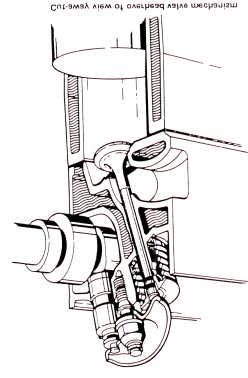
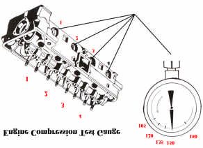
Opel CIH: Engine Compression Test
There are 3 main components to any proper running engine:
Compression, Ignition and Fuel. To efficiently operate an Opel,
you need to start with accurate engine compression figures, as
this can also determine how much performance you may expect.
Compression also affects ignition timing (via vacuum advance)
and fuel input (drawn from the carburetor by vacuum).
Test results also help diagnose repairable problems, and tell you
when you need to rebuild or replace your engine.
Procedure :
(1) Acquire an engine compression gauge (screw-end type is recommended).
(2) Make sure battery is fully charged.
                                                                                                     Compression Tests reveal actual results,
(3) Remove all 4 spark plugs & disconnect coil (+) wire.                                             whether you have an “Early” 1968-1970
(4) Place transmission in Neutral gear setting (Manual) or Park (Automatic) with e-brake on.         higher 9.0 compression pistons, or “Later”
(5) Important: Remove air filter or hardware from top of carburetor, and use a tool to hold          1971-1975 lower 7.6 compression pistons.
    the main throttle plates of the carburetor fully open for the duration of this test.
(6) Screw the engine compression gauge, into spark-plug holes, beginning with #1 cylinder.
(7) Turn the ignition key to “start,” hold for about 8 cranks, then release key.
(8) Observe the highest number the gauge reads (the needle jerks upward about 4 times,
    then levels off), and write it down as the “dry” number for that engine cylinder.
(9) Release gauge pressure button, then repeat procedure on each of the other 3 cylinders.
    If you have any doubt about a particular result, repeat procedure on that cylinder.
(10) Compare the “dry” reading numbers.
    — 180psi in all 4 cylinders is Excellent
    — 150psi in all 4 cylinders is Good (150psi is Very Good for “1971-75” 7.6 engines)
    — About 135psi is factory recommended minimum.
    — About 120psi for all 4 cylinders, an Opel will run “OK” but with little power.
    — 105psi or below, indicates either a mechanical problem on a cylinder,                              Opel 1.9L Piston Types:
          or a worn -out engine if on all 4 cylinders.                                                Left is higher 9.0:1 compression
(11) Squirt about 1/2 tablespoon of clean 30W oil into cylinder under test, then repeat test,         Right is lower 7.6:1 compression
    and write down results as “wet” numbers for each individual cylinder.

                                                                  (12) General Diagnosis :
                                                                  If any one cylinder reads 25% or more below any other 4 cylinders
                                                                  (#4 usually tests a bit lower because the battery slows down),
                                                                  that’s a sign of a problem in that particular cylinder.
                                                                  If “wet” reading is 25% or more than “dry” reading,, that indicates
    Above: Example of Compression Chart                            worn-out or cracked piston rings. Sometimes, using a product like a
    Keep with vehicle, for future reference                        can of “Engine Restore” will temporarily improve low compression.

(13)Additional Diagnosis :
   —If the reading on any cylinder is in the 40psi-80psi range, perform additional “leak-down” test to learn if a valve is worn-out,
   sticking, or damaged. Place the car in neutral gear (or “Park”) with parking brake engaged. Rotate the engine to top-dead-center
   (TDC) for the cylinder being tested (TDC is when both rocker arms are fully elevated at that cylinder), then insert compressed
   air into the spark plug hole and listen for where the air is escaping. If air can be heard out the top of the carburetor, then the intake
   valve isn’t sealing. If air is heard escaping out the exhaust, then the exhaust valve isn’t sealing. If air escapes out through the top
   of the valve cover, the rings are bad. Consider either a valve job and/or a bottom-end engine rebuild, depending on test results.
   — If there is a reading of 40psi to “zero” on a cylinder, that could indicate stuck valve or hole in the piston. Remove the valve
   cover, and observe if one rocker arm stays fixed in a position lower than all the others, when the engine is cranked. A stuck valve
   sometimes loosens with solvent (like WD40). If it is bent, it requires a valve job. A damaged piston will require replacement.
   — If 2 cylinders that are next to each other show lower numbers (usually #2 and #3), this can indicate a warped cylinder head
   and/or a blown head gasket. This is common to 1973-1974 “12-bolt” style Opel cylinder heads (when Opel narrowed the
   coolant passages), and requires removing the cylinder head to “magnaflux” test (for cracks) and a valve job or head replacement.
Additional possibilities for significant engine problems you can inspect for, are:
Valve Mis -adjustment (see Valve Adjustment Tech Tip) or Excessive Camshaft Lobe Wear (Ask Opel expert to diagnose).
Timing Gear Mis -Alignment (Check via procedure in Ignition System section)
Excessive cylinder wear (Have a machine shop measure this, after the cylinder head is removed)
                                                                                                                     www.opelclub.com (6/2006)
Opel 1.9 Engine: Valve Adjustment Procedure
The first step in a valve adjustment on a 1.9L Opel engine,
is knowing what type of camshaft and valve lifters you have.
For most original Opel’s, the main question is if you have:
An “early” 3-bearing camshaft with solid valve lifters
(factory original valve setting is .012” gap “Hot”), or
A “later” 4-bearing camshaft with hydraulic valve lifters
(correct valve setting is 0 lash @ TDC + 3/4 turn on rocker nut)
SOLID HYDRAULIC
NEVER mix camshaft & lifter types — Damage may result!
Opel Lifter Types
Identifying the 3-Bearing “Early” 1968-1970 Solid Lifter Head, Cam or Lifters
(1) Head has NO plug, on the cylinder head casting “spine,” between the #3 intake and exhaust valves
(2) Head has NO 3rd journal or bearing visible (behind the square plate on the side)
(3) Head lower front typically (not always) has 3 protruding “Bars”
(4) Head does NOT have 2 vertical bolts (or bolt holes) in the front of the head
(5) Head date marks typically say “68” “69” or “70”
(6) Cam front “oil groove” extends about 3/4’s (270 degrees) around front journal
(7) Lifter has NO separate cap, and NO small hole on its side
* On some performance cams, an inscription reads “MECH”
** Solid lifters are generally (but not always) found in 1968-1970 Opel cylinder heads
NOTE: It is NOT OK to install a 3-bearing solid lifter type camshaft in a 4-bearing Opel cylinder head,
as this causes significant oil pressure loss when the engine is running (because of the “open” 3rd journal)
Areas to Check: (1): Plug between #3 Valves?
(7): Lifter
(Which type of Opel head, Type?
camshaft & valve lifters?)
(4): Are there 2 allen-head
(Vertical) Bolts in Front?
(6): (2): 3rd Journal
Cam oil Or Bearing?
Groove?
(3): Numbers of “Bars”? (5): Year Marking on Head?
Identifying the 4-Bearing “Late” 1971-1975 Hydraulic Lifter Head, Cam or Lifters
(1) Head has A plug, on the cylinder head casting “spine,” between #3 intake and exhaust valves
(2) Head has a 3rd journal/bearing that is visible (behind square plate)
(3) Head lower front typically has 4, 2 or 1 “Bars”
(4) Head DOES have 2 vertical 6mm allen- head bolts in front (the “12-bolt” style of 1972-later)
(5) Head date marks typically say “71” through “75” or later
(6) Cam front ‘groove’ extends 360 degrees all the way around (or it is not grooved at all)
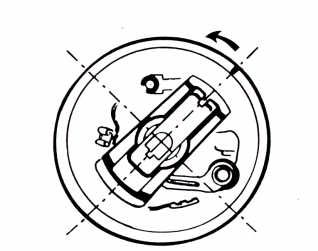
(7) Lifter has a “cap” visible on top, AND small hole on side (as seen on above photo)
* On some performance camshafts, an inscription reads “HYD”
** Hydraulic lifters are generally (but not always) found on 1971 and later Opel cylinder heads
NOTE: It is OK to install a 4-bearing hydraulic lifter cam in 3-bearing solid lifter head, so long as
you also measure for bearing wear, or replace the cam bearings first, and install a set of re-surfaced or new hydraulic lifters.
www.opelclub.com (6/2006)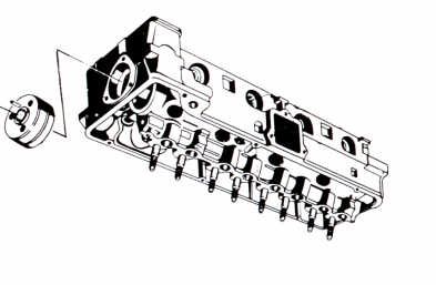
Inspection & Adjustment of Solid Lifters:                                                                             Opel Solid Lifter Valve Adjustment
(1) Remove and inspect the bottom of your solid lifters:
Opel solid lifters are prone to wearing unevenly on their
                                                                                                                                         15mm deep socket
bottom surface, and becoming “dished” there.
Use a 15mm deep-socket, to unscrew and remove each rocker nut,
then (one at a time) remove the rocker arm and bearing, then
remove and inspect the bottom of each solid lifter.
Keep all hardware together in 8 separate baggies or boxes,
with labels for cylinder number, and intake or exhaust valve
 (for later reinstallation). Keep the lifters in same order as removed.
Resurface (at a machine shop) each “dished” solid lifter,                                         .012”
if you plan to re -use your existing solid-lifter camshaft.                                       Feeler
                                                                                                  Gauge
(2) Notes:
On solid-lifter heads, a good idea is to also replace the 8 rocker nuts
(and studs if needed), to assure they hold a consistent gap setting.
If camshaft has been removed, always re-install the camshaft prior to
re-installing the solid lifters.                                                                                                                 Rocker Arm
                                                                                                           Valve Lifter
(3) Re-install good used lifters, only in same lifter bores they came from.                                                                      15mm
Coat new or resurfaced lifters with assembly lube or oil prior to installation.                                                                  Rocker Nut
                                                                                                                                                     and
If installing a new camshaft, always install with 8 new or re-surfaced solid lifters.                                                            Rocker
(4) Install Rocker Arms, Rocker Arm Bearings, and Rocker Nuts                                                                                    Bearing
Reinstall this hardware on the same individual rocker studs they
originally came from. Lightly oil rocker arm bearings.
                                                                                                                                                   Adjust
(5) Rotate Engine to TDC for the #1 Cylinder                                                                                                       Gap Here
See below diagram, to determine correct distributor setting for #1 TDC.
Another way to tell TDC, is the 2 valves are at the “top” of their travel length.                                                                  Valve Stem

(6) Pre-Adjust the 2 Valves for That Cylinder at TDC                                                       Rocker Stud
Use 15mm deep-socket, to slowly tighten each of the 2 rocker nuts down, until you
feel a moderate drag on your feeler gauge (when pulling the a .012” feeler gauge tip
back and forth, within the gap between the bottom of the rocker arm and the top of
the valve stem) for each of the intake and exhaust valves for that cylinder.
(Not much turning is needed: About a 1/8 turn (~45 degrees) changed a solid lifter gap about .010”)

(7) Rotate Engine 90 degrees, to TDC for the #3 Cylinder & Pre-adjust its 2 Valves
(8) Rotate Engine & Repeat Procedure, on the #4 and then the #2 Cylinder Valves
(9) Install Valve Cover, then run engine until warm
Re-check each valve tip –to– rocker arm bottom gap, with .012” feeler gauge, to see that
setting has not changed. If it has, readjust it, to the proper .012” gap setting.
Note: Some higher-performance camshafts, require a setting greater than .012”
Check the instructions that come with individual aftermarket camshafts, for its specified setting
Avoid buying or installing an aftermarket camshaft without knowing (or being provided) its adjustment & specifications!!

                                                                    TDC                                                       Valve Locations & Types:
         TDC
                                                                    For #2                                                    “Staggered” Intake (In) &
         For #4                                                                            #4 Cyl
                                                                    Valves                                                          Exhaust (Ex) Valves
         Valves

                                                                                       #3 Cyl

                                                                      #1Mark
                                                                                       #2 Cyl

                                                                                       #1 Cyl
           TDC                                                        TDC
           For #3                                                     For #1
           Valves         Distributor Locations for TDC               Valves
                                                                                                                     www.opelclub.com (6/2006)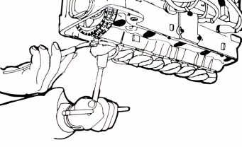
Inspection & Adjustment of Hydraulic Lifters:                                                      Opel Hydraulic Valve Adjustment

(1) Remove and Test lifters
Use a 15mm deep-socket, to unscrew and remove each rocker nut,                                                         15mm deep socket
then (one at a time) remove the rocker arm and bearing, then
remove and inspect each hydraulic lifter for “cupping” on the bottom
surface. Re-surface or replace cupped lifters and inspect camshaft
lobes on badly cupped lifter areas.
Note: If you are installing a new camshaft, Always install new or
re-surfaced hydraulic lifters. If camshaft is not being replaced, always
re-install the old lifters in the same lifter galley that they originated.
(2) Lubricate Lifter and Install
If lifter is new, coat with engine assembly lubricant.
If re-installing a used lifter, verify it still has a light oil coating, and
install only in the same lifter bore it was removed from
(3) Install Rocker Arms, Rocker Arm Bearings, and Rocker Nuts
Reinstall this hardware on the same individual rocker studs they                                                Rocker Arm
originally were removed from. Lightly oil rocker arm bearing.
                                                                                             Tip
(4) Rotate Engine to TDC for the #1 Cylinder
See below diagram, to determine correct distributor setting for #1 TDC.
Another way to tell TDC, is the 2 valves are at the “top” of their travel length.                                   Valve Stem
(5) Pre-Adjust the 2 Lifters for That Cylinder at TDC                                                               Valve Spring
Use 15mm deep-socket, to slowly tighten each of the 2 rocker nuts down, until the tip of
the rocker arm just touches the top of the valve stem. At this point, there is no up or
down movement, and no pressure is being exerted on the valve or lifter — this is called       Illustration of “Side View” of
( “0” Lash @ TDC). If the lifters are new, and have no oil inside them, you can adjust        Opel Rocker Arm and Valve Stem
them 3/4 turn with out the engine running. Note: With new lifters that you have pre-
adjusted, you will need to break them in for 2 minutes on first start up of the engine,     “Zero Lash” setting. is when the tip of
running the engine steadily at 2000 rpm. If you are re -using the old lifters and they have the rocker arm, just touches the top of
oil in them, you will need to finish setting all the valves to “0” lash @ TDC and adjust the valve stem (no gap is present).
them 3/4 turn in 1/4 turn increments with the engine running. NOTE: Factory recommenda-
tion of one full turn from zero lash, is too tight.                                                                              About
(6) Rotate Engine to TDC for the #3 Cylinder, Pre -adjust its 2 Lifters                                                          3” deep
                                                                                                                                 plate
(7) Repeat Procedure, on #4 and #2 Cylinder Lifters
(8) How to Adjust Hydraulic Lifters on Running Engine
First you will need to fabricate an “oil deflector shield” that sits above the timing chain,
to keep the hot oil from splashing all over the engine compartment & on you.
(8a) Run engine until warm, then loosen one rocker nut one full turn (360 degrees) or
until that valve starts to make a clattering sound. Do this for each of the remaining 7
rocker nuts. Turn off engine. Refer to step 5-7 above, (for used lifters), to set the “0”
Lash @ TDC.
(8b) Start engine and let it idle, tighten each of the 8 rocker nuts 1/4 turn (90 degrees). Repeat this 2 more times for a total of
3/4 turns on all 8 rocker nuts. It is normal for engine to slow down during this procedure.
Note: An “old school” trick for determining optimum valve settings, is to connect a vacuum gauge to the brake booster hose
outlet fitting on the intake manifold, then adjust the 15mm rocker nut to where it obtains the maximum vacuum psi reading on
the gauge.
                                                      TDC                                                    Valve Locations & Types:
TDC
                                                      For #2                                                 “Staggered” Intake (In) &
For #4                                                                         #4 Cyl
                                                      Valves                                                       Exhaust (Ex) Valves
Valves

                                                                         #3 Cyl

                                                                         #2 Cyl
                                                       #1Mark
                                                                         #1 Cyl
  TDC                                                  TDC
  For #3                                               For #1                                        www.opelclub.com (6/2006)
  Valves          Distributor Locations for TDC        Valves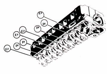
OPEL MOTORSPORTS CLUB
OMC is an independent US-based auto club, that
specializes in German- made 1968-1975 Opels.
OMC was founded in 1980 by Opel enthusiasts
who wanted to share information and promote their
marque in motorsports. A newsletter was established
to promote Opel events, report Opel-related news,
provide technical tips, discuss vehicle upgrades,
and give members a free place to advertise.
New “Full Memberships” receive:
A year of bi- monthly print issues of OMC newsletter “The Blitz,” a roster of club members, an OMC decal
and a window emblem. Members can also participate in local OMC chapter activities, held all over the USA.

        OMC Newsletters: “THE BLITZ”
        (Print version black/white; Online in color)                            OMC Activities & Annual Meeting

Opel Motorsport Club is the longest-established Opel club in the U.S.A. Members travel great distances
to attend the OMC Annual Meeting, a mid-Summer gathering and display of classic and restored Opels.
Benefits of membership also include information from other Opel owners on the maintenance and
improvement of their Opel(s), and the ability to contact fellow members on their common interests.
Opel Motorsport Club funds help maintain our website (with helpful Opel information) at: www.opelclub.com

OMC’s peer-reviewed technical information helps owners avoid common and costly errors on Opel repair jobs!
OMC is officially recognized by the Opel factory of Russelsheim, Germany, and OMC “SOLO II” racing
activities are also sanctioned by the SCCA (Sports Car Club of America) for racing nationwide in the USA.

“Full” U.S. Membership: $45.00 (Includes bi-monthly b/w print issues of The Blitz, postage & benefits listed above)
“Online-Only” Member: $20.00 (Includes downloadable Acrobat .pdf version of The Blitz, for home color printing)
               To Join: Send your name & address, with check/money order payable to “Opel Motorsports Club” by mail to:
                               OMC Treasurer, 3824 Franklin Street, La Crescenta CA 91214-1607
                                    OR: Send $47 for Full US Membership or $22 for Online Membership,
                                                 via PayPal to: JoinOMC@opelclub.com
                      (International Members: Please Add $10. for Full Membership, to cover additional postage costs )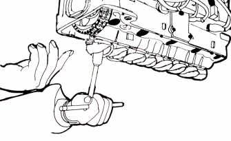
You can also read