Use It Free: Instantly Knowing Your Phone Attitude
←
→
Page content transcription
If your browser does not render page correctly, please read the page content below
Use It Free: Instantly Knowing Your Phone Attitude

                                Pengfei Zhou, Mo Li                                                                  Guobin Shen
              Nanyang Technological University, Singapore                                                 Microsoft Research, China
                         {pfzhou, limo}@ntu.edu.sg                                                       jackysh@microsoft.com

ABSTRACT
The phone attitude is an essential input to many smartphone ap-
plications, which has been known very difficult to accurately esti-
mate especially over long time. Based on in-depth understanding
of the nature of the MEMS gyroscope and other IMU sensors com-
monly equipped on smartphones, we propose A3 – an accurate and
automatic attitude detector for commodity smartphones. A3 pri-
marily leverages the gyroscope, but intelligently incorporates the                                                Real-time attitude              Real-time attitude

accelerometer and magnetometer to select the best sensing capa-
bilities and derive the most accurate attitude estimation. Extensive
experimental evaluation on various types of Android smartphones                                      (a) Initial attitude estimation.   (b) Attitude estimation after 1
                                                                                                                                                   minute.
confirms the outstanding performance of A3 . Compared with other
existing solutions, A3 provides 3× improvement on the accuracy
of attitude estimation.                                                                       Figure 1: Phone attitude tracking error of a popular smart-
                                                                                              phone app.
Categories and Subject Descriptors                                                            positions such as in hands, pockets, or bags, and make complicated
C.4 [Performance of Systems]: Modeling techniques, Performance                                motion styles. Figure 1 shows the phone attitude estimation re-
attributes; C.5.3 [Computer System Implementation]: Portable                                  sults of a popular Android app1 using the gyroscope. Figure 1(a)
devices                                                                                       depicts the initial attitude estimation and Figure 1(b) depicts the
                                                                                              estimation for the same phone attitude after 1 minute random mo-
Keywords                                                                                      tion. Obviously, there is a significant difference in the two attitude
                                                                                              estimates, which corresponds to the phone attitude tracking error.
Mobile Phone Attitude, Gyroscope, IMU Sensors, Attitude Cali-                                 Some recent research works exploited the gyroscope for heading
bration                                                                                       direction estimation. Their reports also confirmed the severity of
                                                                                              gyroscope drifts in minute level runs even when the mobile phone
1.     INTRODUCTION                                                                           is held relatively still to the user [19, 22, 24]. Although there have
   The phone attitude gives the 3D orientation of the phone with re-                          been many efforts made to address a similar problem (rigid body
spect to the earth coordinate system. It is an essential input to many                        orientation) in robotics domain [14, 15, 8, 16], our study reveals
phone applications including mobile gaming, 3D photography [12,                               that directly adopting those approaches cannot provide satisfactory
18], gesture and activity recognition [17, 20], dead reckoning based                          performance, mainly due to the lack of fundamental understand-
localization and navigation [11, 24, 25, 26], etc. Since the first inte-                      ing of the MEMS gyroscope and other IMU (Inertial Measurement
gration into smartphones in 2010, the MEMS gyroscope, capable of                              Unit) sensors on smartphones. As a concrete example, current An-
measuring the 3 dimensional angular velocities, has been exploited                            droid API directly borrows existing Kalman-based sensor fusion
to estimate phone attitude by continuously integrating the angular                            techniques to estimate the phone attitude and suffers significant per-
velocities. However, unlike those high precision gyroscopes used                              formance degradation in many conditions.
in nautical, aviation and robotic navigation systems, the MEMS                                   In this paper, we conduct detailed experimental study to under-
gyroscope has been widely blamed for its poor accuracy.                                       stand the fundamental performance of the MEMS gyroscope. We
   The problem becomes particularly challenging in practice as peo-                           follow the device specification and conduct controlled experiments
ple may take their phones in arbitrary ways, hold in different body                           to investigate how different environmental factors impact on the
Permission to make digital or hard copies of all or part of this work for personal or
                                                                                              gyroscope performance and how the best accuracy can be achieved
classroom use is granted without fee provided that copies are not made or distributed         in an appropriate condition range. We also characterize the nature
for profit or commercial advantage and that copies bear this notice and the full cita-        of two other IMU sensors on smartphones, the accelerometer and
tion on the first page. Copyrights for components of this work owned by others than           compass, to understand their performance in different conditions.
ACM must be honored. Abstracting with credit is permitted. To copy otherwise, or re-          Based on such comprehensive understanding, we propose to esti-
publish, to post on servers or to redistribute to lists, requires prior specific permission   mate the phone attitude primarily based on the 3-axis angular ve-
and/or a fee. Request permissions from permissions@acm.org.
MobiCom’14, September 7-11, 2014, Maui, Hawaii, USA.                                          1
Copyright 2014 ACM 978-1-4503-2783-1/14/09 ...$15.00.                                           The app is called "Android Sensor Box" available at Google Play
http://dx.doi.org/10.1145/2639108.2639110.                                                    with about 1,000,000 downloads.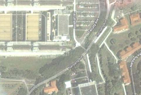
locities obtained from the gyroscope, but also incorporate the com-                   App                Type           Time     Error
pass and the accelerometer for opportunistic calibration. The three          3D camera (Android)     3D photography     4mins     40◦
types of IMU sensors are of different natures and their accuracy                 Seene (iPhone)      3D photography     3mins     25◦
varies in different condition ranges. In particular, the gyroscope           Sensor Box (Android)      mobile app      3 mins     65◦
provides a cumulative estimation of the attitude through continu-               Jenga (Android)          game          6 mins     35◦
ous integration on angular velocities that is accurate in general but            Jenga (iPhone)          game          5 mins     30◦
suffers from error accumulation. On the other hand, the compass               Showdown (iPhone)          game          10 mins    38◦
sensor and accelerometer provide instant attitude estimation with-
out cumulative errors but the accuracy is highly instant environment    Table 1: The attitude estimation error measured from popular
and motion dependent. We develop a practical approach that cal-         apps.
ibrates the cumulative gyroscope estimation when we have higher
confidence in compass and accelerometer readings. In practical us-      navigation studies, tracking the phone attitude yields the heading
age, it is non-trivial to identify "good" calibration opportunities.    of people movement for trajectory mapping.
Intuitively, the compass sensor outputs accurate geomagnetic north         The gyroscopes have been playing a critical role in estimating
when the phone is outdoor and the gravity direction can be accu-        phone attitude since the first integration to smartphones in 20102 .
rately extracted from accelerometer when the phone is static. Such      Recent use experience, however, suggests that poor accuracy can
opportunities, however, would be too few in practice to provide         be achieved for long period of tracking. Table 1 lists the measured
timely calibration. In this work we propose an "opportunistic cali-     errors of some popular apps from Google Play and Apple Store.
bration" technique that looks at the concordance of the three types     The apps typically bear 25◦ ∼65◦ errors within less than 10 min-
of sensors in estimating short period attitude changes. High consis-    utes, which significantly impair the use experience. For example,
tency indicates high instant confidence of the compass and gravity      the 3D photography apps like the "3D Camera" for Android and
outputs and thus a positive calibration opportunity. Sufficient cali-   "Seene" for iPhone track the phone attitude when users take multi-
bration opportunities can be identified using this approach.            ple pictures and then combine different pictures into one based on
   We incorporate the proposed design and techniques and develop        the estimated phone attitude. The big attitude estimation error can
A3 , an Accurate and Automatic Attitude detector for smartphones.       result in obvious distortion of the final generated picture. In the
A prototype system is implemented and comprehensively tested            "Jenga" game, the phone attitude is tracked and taken as input. The
with three types of Android smartphones, including HTC Sensa-           user can change the perspective of view to fully inspect a 3D Jenga
tion, Samsung i9100, and LG Google Nexus 4. We evaluate the             tower by rotating the phone. The large cumulative tracking errors
performance of A3 across various scenarios and in multiple popular      require frequent reset of the phone attitude from the user. In dead
apps, and compare A3 with other possible competitors. The exper-        reckoning based localization, accurately detecting the user heading
iment results demonstrate that A3 provides 3× improvement over          is important but remains unsolved. As the user walks, the localiza-
alternative solutions. Higher performance gain can be achieved the      tion error due to the heading error is rapidly accumulated, which is
user motion is intense (e.g., running). Meanwhile, the power con-       up to 20m within 10 mins according to recent studies [22, 24].
sumption of A3 is measured moderate and acceptable for long runs           One cause of such errors is the limited precision of the state-
on commodity smartphones.                                               of-the-art MEMS gyroscope. Compared with high precision gy-
   The contribution of this work includes (1) detailed studies to un-   roscopes like the Fiber Optic Gyroscope (FOG) that can achieve
                                                                                                ◦
derstand the basic performance of smartphone IMU sensors and            stability down to 10−4 /h, the MEMS gyroscope is manufactured
their sensitivity to environments; (2) based on such understand-        with low cost based on the Coriolis Vibrating Gyroscope (CVG)
ing, a novel and practical smartphone attitude estimation method        principle. In CVG, as the plane of oscillation is rotated, the re-
which intelligently exploits the sensing redundancy of the gyro-        sponse detected by the transducer is due to the Coriolis term in its
scope, compass and accelerometer; and (3) a prototype system of         equations of motion. CVG translates the response into the instant
A3 on Android platform which outperforms existing competitors           3-axis angular velocities of the phone and continues integration has
in various environments and conditions. To our knowledge, A3            to be performed on the output to obtain angular increments over the
significantly pushes forward the state-of-the-art of phone attitude     previous attitude. Instantly detecting the absolute attitude thus re-
estimation. A3 makes it practically feasible to instantly obtain the    lies on precise tracking of phone attitude changes, which is known
phone attitude in free motion and for long runs.                        of substantial cumulative errors.
   The rest of the paper is organized as follows. §2 presents the          Although no much progress has been made for improving the at-
background and motivation of our problem. §3 describes the prin-        titude detection accuracy in the field of mobile phone study, many
ciple of MEMS gyroscopes in attitude tracking and characterizes         efforts have been made in robotics domain to address a similar
its performance. §4 studies the compass sensor and accelerometer,       problem, i.e., estimating rigid body orientation. Recent studies in
and describes how they can be leveraged to calibrate gyroscopes.        robotics [14, 8, 16, 15] explore the capabilities of magnetometers
§5 describes the opportunistic calibration technique and presents       and accelerometers in orientation estimation, and integrate with the
the final A3 system design. §6 presents the experimental evalua-        gyroscopes to improve the accuracy. The devised MARG (Mag-
tion results. §7 discusses the related works and §8 concludes this      netic, Angular Rate, and Gravity) orientation for robotic systems
paper.                                                                  performs sensor fusion with input from all three types of sensors to
                                                                        derive the final estimation. Detailed review of related works will
                                                                        be given in Section 7. The performance and characteristics of the
2.    BACKGROUND AND MOTIVATION                                         sensors used in robotic systems are different from those used on
   Instantly knowing the phone attitude is essential to many appli-     smartphones. For example, compared with the MEMS gyroscope
cations. For example, the phone attitude can be treated as a key        on smartphones, the mechanical and START [1, 8, 21] gyroscopes
user input for enhanced entertainment in many gesture-based mo-
bile phone games. In 3D photography, the instant phone attitude         2
                                                                         iPhone 4 was the first smartphone model that integrates the 3-
information helps to retrieve accurate depth information from the       axis gyroscope. Gyroscopes were later widely integrated in other
pictures taken. In recent dead reckoning based localization and         Android and Windows Phone devices.
ωy
                        ωz                Ze                                phone body-frame. Xe (pointing to the Earth east), Ye (pointing
                                                         Roll               to the earth north) and Ze (parallel with the gravity) are the three
                       Yaw                                                  reference axes in the geo-frame. With continuous integration, the
                                  γ                                         phone attitude can be calculated and represented as the relative dif-
                                               β                            ference of the two coordinate systems, which can be described by
                                  O                                 Ye      a rotation matrix, or the angles between the three supporting axes
                                      α                         (north)     in the two frames, i.e., α, β, and γ (shown in Figure 2).
                                                   Pitch                       The MEMS gyroscope has been widely blamed for its poor per-
                          Xe                                                formance and rapid error cumulation. In this study, however, we
                         (east)                     ωx
                                                                            find many existing works did not make full efforts to comprehen-
                                                                            sively understand the MEMS gyroscope working rationale and per-
                                                                            formance characteristics, leading to suboptimal or inappropriate
Figure 2: The output of the MEMS gyroscope is 3 angular ve-                 use of them. For example, the following presents a segment of
locities around the Roll, Y aw, and P itch axis in the phone                the code for integrating the 3-axis angular velocities provided in
body-frame.                                                                 "Android Developers" site [2].
used in robotic systems are based on different physical rationales,         //Axis of the rotation sample
and usually have higher accuracy but different frequency responses          float axisX = event.values[0];
to motions. No existing studies, however, have quantitatively un-           float axisY = event.values[1];
derstood the nature of smartphone MEMS sensors and their perfor-            float axisZ = event.values[2];
mance in different condition ranges. As a result, straightforward           // Calculate the angular speed of the sample
                                                                            float omegaMagnitude = sqrt(axisX*axisX +
sensor fusion, e.g., Kalman-based approaches [14, 8, 16] with un-               axisY*axisY + axisZ*axisZ);
sorted sensor input, cannot guarantee high accuracy. Besides, the           // Normalization
motion patterns and usage environments of robotic systems are also          ...
very different with those of smartphones. To our knowledge, sim-            // Integrate around this axis with the angular
ply migrating the approaches for robotic systems to smartphone                  speed by the timestep into a quaternion
platforms results in suboptimal performance. For example, the               float thetaOverTwo = omegaMagnitude * dT / 2.0f;
                                                                            float sinThetaOverTwo = sin(thetaOverTwo);
Android API getRotationMatrixFromVector() directly                          float cosThetaOverTwo = cos(thetaOverTwo);
adopts existing Kalman-based sensor fusion algorithms to calcu-             deltaRotationVector[0] = sinThetaOverTwo * axisX;
late the phone attitude. As the experimental evaluation reveals, the        ...
estimation error of Android API may reach 40◦ or higher in many
cases.                                                                         According to Euler’s rotation theorem, any rigid body rotation
   In this paper, we comprehensively characterize the nature of the         can be represented by a single rotation about some rotation axes.
MEMS gyroscopes on modern smartphones, and derive optimized                 The above code assumes a fixed rotation axis3 in the body-frame at
settings and techniques to improve the gyroscope performance in             any particular integration interval, and calculate omegaMagnitude
practical working conditions. We then incorporate the compass               as the resultant rotation velocity of the phone. In practice, as the
and accelerometer. While the gyroscope detects 3-axis angular ve-           phone rotates, the rotation axis of the phone keeps changing in
locities, being able to remove 3 degrees of freedom, the compass            the body-frame and estimating rotation axis in the geo-frame us-
measures the geomagnetic north and the 3-axis accelerometer can             ing the resultant velocity in the body-frame is inappropriate. Such
derive the gravity direction from the 3 axis linear acceleration, pro-      a method results in significant error accumulation, especially when
viding the capability of removing another 3 degrees of freedom.             the sampling rate cannot keep up with the shift of phone rotation
We thus develop an intelligent calibration approach which selects           (which unfortunately is true in most cases as the sampling rate is
the best 3 degrees of freedom to determine the phone attitude based         usually capped at around 600Hz for the MEMS gyroscope). Above
on quantitative error estimation of the three different IMU sensors         code logics have been practiced in the current Android OS, i.e.,
under different condition ranges. Our approach roots in the com-            handleGyro() [3] in operating the gyroscope output to derive
prehensive understanding of smartphone IMU sensors and thus fun-            the attitude for its API. The method calculates the rotation axis in
damentally outperforms existing competing solutions.                        the geo-frame based on the phone angular velocity measured in the
                                                                            body-frame.
3.    UNDERSTANDING MEMS GYROSCOPE                                             In this paper we apply the Euler Axis/Angle method to do the
                                                                            integration and tackle the problem from the perspective of the geo-
   The MEMS gyroscope used in smartphones detects the 3-axis                frame, which is fixed during the phone motion. The method finds
angular velocities of the phone. To derive the instant phone at-            an equation for the rotation speed in the geo-frame based on dif-
titude, we need to perform continuous integration on the angular            ferential. As the equation is directly constructed in the geo-frame,
velocities.                                                                 there is no need to make assumption on fixed rotation axis. During
                                                                            the integration, the total phone motion time is divided into multi-
3.1     Angular Velocity Integration                                        ple time slots and the phone rotation is a sequential combination of
   We deal with two coordinate systems in deriving the phone at-            the rotation within each slot. The mathematical illustration of the
titude. One is the earth coordinate system (we call "geo-frame" in          method is detailed in Appendix §A.
this paper) and the other is the smartphone body coordinate system
(we call "body-frame" in this paper). The goal is to get the phone
attitude in the geo-frame, i.e., to calculate the relative difference be-   3
                                                                              The rotation of a three-dimensional object is always around an
tween the body-frame and geo-frame. Figure 2 depicts the output             imaginary line which is called the rotation axis which may keep
of the MEMS gyroscope, which is real-time angular velocities (ωx ,          changing during the rotation. The rotation axis may not pass
ωy , and ωz ) around the Roll, Y aw, and P itch axis in the smart-          through the object’s body.
3.2 Practical Settings and Techniques Parameter
Sensor
Typ Unit
Settings/Conditions
Sensor specifications and configuration. The ADIS1626x se-
ries of MEMS gyroscopes are widely used in many smartphone r = ±320◦ /sec, b = 330Hz 0.9 ◦ /sec (rms)
models like HTC Sensation series smartphones. Some other gyro- Output r = ±320◦ /sec, b = 50Hz 0.4 ◦ /sec (rms)
scope models like the AGD1 2022 FP6AQ MEMS gyroscope (used noise r = ±160◦ /sec, b = 50Hz 0.2 ◦ /sec (rms)
in iPhone) has similar performance. In this paper, we primarily r = ±80◦ /sec, b = 50Hz 0.1 ◦ /sec (rms)
study the ADIS1626x series and the performance of other models Temperature ◦ /sec/◦ C
ADIS 1626x 0.005
can be inferred. For a typical MEMS gyroscope, there are multi- coefficient
ple sensor dynamic range r selections (e.g., ±320◦ /sec, ±160◦ /sec Linear ◦ /sec/g
Any axis 0.2
and ±80◦ /sec for ADIS1626x series) and sensor bandwidth b se- acceleration
lections (e.g., 50Hz and 330Hz for ADIS1626x series). The sen-
sor bandwidth sets a cut-off frequency in responding to phone mo- Table 2: The key specifications of the ADIS1626x series of
tions. A higher bandwidth setting can measure higher frequency MEMS gyroscopes. The "Typ" column gives the typical out-
motion and vibration. Table 2 depicts a part of the data sheet of the put noise for a certain setting. r is the sensor dynamic range
ADIS1626x series gyroscope. For different selections of the sen- and b is the sensor bandwidth (also called "cut-off frequency").
sor dynamic range and bandwidth, the output noise is different. As
shown in Table 2, the output noise under the setting "r = ±80◦ /sec, Android method, the 90th percentile and medium errors, however,
b = 50Hz" is 0.1◦ /sec. The noise level increases when larger dy- are much higher, 27.5◦ and 19.8◦ , respectively. For the 5 minute
namic range or higher sensor bandwidth is selected. Due to the walks, the 90th percentile and medium errors of our method are
high degree of phone motion, "r = ±320◦ /sec, b = 330Hz" is the 31.2◦ and 22.3◦ , respectively, and those of the Android method
default setting for most smartphones. According to the data sheet, are up to 103◦ and 79◦ , respectively. From the experiment results,
the temperature and linear acceleration affect the output noise of we see that the MEMS gyroscope is able to provide significantly
the gyroscope as well, which we will later investigate for practical improved quality of attitude tracking with the Euler Axis/Angle
understanding. method and our optimization techniques.
Practical settings and techniques. According to the default set-
ting in smartphones (r = ±320◦ /sec and b = 330Hz) and the 3.3 Performance Characterization
Nyquist theorem, we set the sensor sampling rate to be 660Hz. We further do controlled experiments to understand the MEMS
Typically the MEMS gyroscope cannot support higher sampling gyroscope performance in different condition ranges of different
rate due to hardware limitations. Determining the window size Tw environmental factors.
for integrating the angular velocities needs careful consideration. Temperature. The temperature for the best MEMS gyroscope
Generally small Tw provides finer granularity in performing the in- performance is 25◦ C. For MEMS gyroscopes in smartphones, how-
tegration but too small Tw leads to aggressive computation which ever, the temperature compensation has already been done in the
is not necessary if the phone motion is low and may exceed the sensor chip with an embedded temperature sensor. The calibra-
processing capacity of the phone. On the other hand, as long as Tw tion temperature range is -40◦ C∼+85◦ C with a single temperature
is set fixed, no matter how small it is there are always chances that point calibration. As suggested in Table 2, the temperature coef-
the angular velocities suddenly change within the window, leading ficient is merely 0.005◦ /sec/◦ C. In order to better understand the
to inaccurate integration. In this paper, we apply adaptive integra- impact of temperature, we vary the environment temperature from
tion interval for performing angular velocity integration. We use -20◦ C to +45◦ C and study the sensor performance. According to
the Euler Axis/Angle method introduced in §3.1 to integrate the the experiment result, the estimation error caused by the tempera-
measured angular velocity for each individual interval when the an- ture variation lies within a very small range (1 1
POWER
SUPLY
0.8 0.8 DIMMER
0.6 0.6
CDF
CDF
0.4 0.4
MOTOR
10s
Euler Axis/Angle 1min 5mins
0.2 Euler Axis/Angle 5mins 0.2 10mins
Android code 1min 1min
Android code 5mins
0 0
0 20 40 60 80 100 120 0 20 40 60 80 100
Error (degree) Error (degree)
Figure 3: Phone attitude estimation re- Figure 4: MEMS gyroscope error for dif- Figure 5: Gyroscope measurement de-
sults of different methods. ferent tracking time. vices.
0.7 1.25
We see that for both motion factors, the gyroscope tracking error is
0.6
1 relatively small, stable and controlled for a certain safe range, e.g.,
Error (degree/s)
Error (degree/s)
0.5
0.75
ω < 240◦ /sec and a < 2g. When those "out-of-range motions"
0.4
occur, the error rapidly goes up and becomes unbounded to predict.
0.3 0.5
Such out-of-range smartphone motions are common in daily smart-
0.2
0.25 phone usage such as strong swings when playing mobile games,
0.1
vibration and rotation in the pocket during running, etc. It sig-
0 0
0 100 200 300 400 0 10 20 30 nificantly pollutes the consequent attitude estimation result as the
Angular velocity (degree/s) Linear acceleration (m/s2)
phone attitude is calculated with continuous integration.
(a) Error v.s. angular velocity. (b) Error v.s. linear accelera- Based on the experiments, the MEMS gyroscope performance
tion.
can be summarized as follows:
Figure 6: Impact of (a) angular velocity and (b) linear acceler- • The attitude tracking error accumulates as the time increases.
ation on the MEMS gyroscope performance. If the phone motion is within the safe range and sensor band-
width, the gyroscope tracking result is accurate in a short
Motion. The smartphone motion is typically a combination of time period.
rotational and translational motion. Thus we investigate two mo-
tion factors, i.e., the angular velocity ω and linear acceleration • The attitude tracking error is highly related to the phone mo-
a. Although the translational motion does not change the phone tions, i.e., the angular velocity and linear acceleration. The
attitude, it may influence gyroscope performance. Table 2 sug- high out-of-range motion significantly pollutes the conse-
gests that the sensor output error caused by linear acceleration is quent attitude tracking result.
0.2◦ /sec/g, but the linear acceleration range, within which the gy-
roscope can work comfortably, is unclear. Meanwhile, what is the
impact of the angular velocity within and out of the dynamic range 4. INSTANT ATTITUDE DETECTION
(±320◦ /sec) needs further study. The basic MEMS gyroscope performance cannot provide contin-
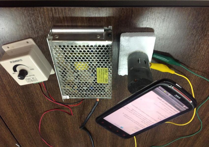
To investigate the impact of angular velocity, we put the phone uous high accuracy attitude detection due to the error cumulation
on a rotation plate, the rotation velocity of which is controlled and out-of-range phone motions. In this section, we describe how
by an adjustable motor (shown in Figure 5). The motor is con- we incorporate the independent measurements from the compass
trolled through a sliding rheostat by adjusting the input voltage. and accelerometer to assist the gyroscope in tracking the phone at-
We test different velocities and for each velocity setting, we rotate titude.
the phone 30 rounds and repeat the experiment for 10 times. To
investigate the impact of linear acceleration, we put the phone in 4.1 Compass and Accelerometer
a sloping track and force it to speed. We intentionally control the Compass. The compass measures the geomagnetic north from
slope and thrust force to provide different linear accelerations. The the detected geo-magnetic field. The accuracy, however, is unsta-
actual runtime acceleration is measured by the accelerometer. ble, especially indoors where steel structures and electrical appli-
Figure 6(a) and (b) plot the tracking error under different set- ances may significantly distort the geo-magnetic field. Recent stud-
tings, which is the accumulated error in degree per second. Figure ies report reasonably high compass accuracy for outdoor usage but
6(a) shows that although the dynamic range of angular velocity is complicated performance for indoor usage [11, 27]. Figure 7 plots
±320◦ /sec, when ω < 240◦ /sec, the error cumulation is small, the estimated earth north using the compass indoors and outdoors.
stable, and roughly proportional to the angular velocity, usually In the experiment, we keep the phone attitude unchanged and move
smaller than 0.08◦ /sec. When ω > 240◦ /sec, the rate jumps up around indoors and outdoors. The compass earth north estimation
significantly. It could be as big as 0.2◦ /sec for ω = 280◦ /sec and is recorded and then compared to the ground truth to calculate the
0.4◦ /sec for ω = 360◦ /sec, respectively. Meanwhile, the error error. For most of the time, we see accurate outdoor compass out-
exhibits significant variation and becomes hard to predict. Figure put, i.e., < 5◦ error. The indoor compass output is much more com-
6(b) shows the error cumulation caused by the linear acceleration plicated that it could be more than 50◦ off the ground truth (from
is relatively higher. When a < 2g, the error cumulation rate is the 30th to 60th second) or as low as a few degree error (from the
relatively stable, roughly proportional to the instant acceleration start to 10th second) at particular moments. Generally, the outdoor
and usually smaller than 0.2◦ /sec. When a > 2g, the output er- compass output is of reasonable quality and much more reliable
ror quickly rises and becomes uncontrolled. It can be as high as than the indoor output. The indoor output accuracy varies signifi-
0.5◦ /sec for a = 2.4g and 0.75◦ /sec for a = 3.2g, respectively. cantly depending on the instant ambient environment.100
Outdoor
Ze
Indoor
Ground Truth
Y
Angle (degree) Cone
50
0
O
δ Ye
−50
0 15 30 45 60 75
Time (s)
Xe Y
Figure 7: Indoor and outdoor compass performance. Figure 8: Attitude from the compass and gravity.
Accelerometer. Most smartphone platforms provide the API 40
of retrieving gravity (e.g., Sensor.TYPE_GRAVITY in Android Gyroscope
and GLGravity in Apple iOS) from the accelerometer readings. 30 Compass
Error (degree)
With the help of the powerful Butterworth filter [9], the accel- Gravity
eration caused by phone motion can be filtered out and the fre- 20
quency components of gravity can be extracted, i.e., the direction
of Ye in the smartphone body-frame. We denote the components 10
of gravity along the X, Y and Z axis to be (gx , gy , gz ), where
p
gx2 + gy2 + gz2 = g. The filter cut-off frequency is normalized to 0
0 1 2 3 4 5 6 7 8
1 radian/sec and the frequency response (gain) is Time (min)
r
1 Figure 9: The performance of gyroscope, compass and ac-
G(ω0 ) = , (1)
1 + ω0 2n celerometer in an instant trajectory.
where ω0 is the angular frequency and n is the number of poles eter perform in very different ways. They have the opportunity to
in the filter. The smartphone motion is typically composed of the produce a few very good estimations but many bad ones as well.
rotational and translational parts, both of which may cause acceler- The estimation errors depend on instant phone statuses and do not
ation variation along the 3 axes. According to the Butterworth filter accumulate. Such different natures in their performance provide us
rationale, if the noise frequency is higher than its cut-off frequency, the opportunity to complement the gyroscope estimation with cali-
the high frequency signal caused by the translational motion can bration from the compass and accelerometer at "good" moments.
be filtered out. The noise caused by the phone rotation, however,
cannot be fully filtered out if the rotation frequency is high. The fre- 4.2 Putting It All Together
quency response (gain) G(ω0 ) of Butterworth filter becomes small We incorporate the three IMU sensors and propose A3 , an ac-
when ω0 gets big. Generally the gravity can be accurately extracted curate and automatic attitude detector to continuously estimate the
when the phone rotation is slight and no constant linear acceleration phone attitude. Figure 10 illustrates the A3 system architecture.
is imposed. A specific example is when the phone is put static. There are two major components: gyroscope tracking and calibra-
Attitude from compass and gravity. As depicted in Figure 8, tion. As depicted in Figure 10 (left), A3 tracks the phone attitude
given the direction of gravity on the phone body-frame, the phone using the gyroscope. The angular velocities are adaptively inte-
attitude is constrained on a conical surface in the geo-frame. On grated to calculate the phone attitude (the rotation matrix R). The
the other hand, the compass outputs the angle δ between Y 0 and tracking error Eg of the gyroscope is carefully estimated based on
Ye axis (pointing to the earth north) in the geo-frame, where Y 0 the real time monitoring of the phone motion. As summarized in
is the projection of Y axis of the body-frame on the Xe -Ye plane §3.3, the MEMS gyroscope error is mostly related to the two mo-
of the geo-frame. Considering the angle δ between Y 0 and Ye , tion parameters, i.e., the angular velocity ω and linear acceleration
we can thus uniquely fix the phone attitude on the conical surface. a. In this paper, we assume the impact from the two parameters
This provides us an alternative of removing 3 degrees of freedom is independent, i.e., the phone’s rotational and translational motion
to determine the phone attitude if we have accurate compass and independently affects the measurement of Coriolis vibration. For
gravity output. The detailed construction of the rotation matrix for each integration interval i, the accumulated error ei is thus mea-
the phone attitude is provided in Appendix §B. sured as
Compared with gyroscope. The attitude estimation from the
compass and accelerometer is independent and of different nature ei = fω (ωi )∆ti + fa (ai )∆ti ,
compared with the result from the gyroscope. The compass and where fω is a functional relationship between the angular velocity
accelerometer give instant status estimation which is unrelated to ωi and the error, and fa is a functional relationship between the
any previous estimations, while the gyroscope gives a cumulative linear acceleration ai and the error. ∆ti is the length of the tracking
estimation of the attitude through continuous integration on angu- interval. The gyroscope tracking error at time tx is accumulated as
lar velocities. Figure 9 compares the attitude estimation from the
tx tx
gyroscope and that from the compass and accelerometer during an X X
8 minute walk. We see a clear difference in the natures of their Eg (tx ) = ei = [fω (ωi )∆ti + fa (ai )∆ti ], (2)
t=t0 t=t0
estimations. In most of the time, the gyroscope produces small
estimation errors which, however, accumulate with time. A few where t0 is the start point of current tracking. fω and fa can be
sudden jumps of the error (e.g., in the 5th minute, probably due determined according to the experimental understanding from Fig-
to out-of-range phone motion) significantly contribute to the final ure 6. When the angular velocity ω < 240◦ /sec, the estimation
cumulative error. On the other hand, the compass and accelerom- error follows a Gaussian distribution with limited variation. The(a) Real time sensor output
Real-time Phone
60 Gyroscope
Attitude A Compass
Angle (degree)
30
Opportunistic 0
Calibration
B
−30
Gyroscope
Calibration −60
Tracking 0 2 4 6 8 10 12 14 16 18 20 22 24 26 28 30 32 34
(b) Time series similarity
0.6
Similarity
0.4
Gyroscope Accelerometer Compass Indoor/outdoor
0.2
Figure 10: A3 architecture. 0
(c) Compass estimation error
60
mean linearly increases as ω increases towards 240◦ /sec. When
Error (degeree)
45
ω > 240◦ /sec, the error rises much higher with intensified vari-
30
ation, being hard to predict. Thus in A3 system, we set fω lin-
ear for the safe range when ω < 240◦ /sec and unbounded when 15
ω > 240◦ /sec: 0
0 2 4 6 8 10 12 14 16 18 20 22 24 26 28 30 32 34
Time (s)
0.0003ω, if ω < 240◦ /sec
fω (ω) = ◦
unbounded, if ω ≥ 240 /sec. Figure 11: The time series similarity of compass and gyroscope
The impact of the linear acceleration a is similar with the angu- sensor output, and the related compass error.
lar velocity , with a < 2g a safe range where the error linearly
tion technique to identify more "good" opportunities. The basic
increases with a and a > 2g of unbounded error:
idea is that we leverage the gyroscope estimation to capture phone
0.001a, if a < 2g attitude dynamics. As our experiments reveal in §3.3, the gyro-
fa (a) = scope can provide very accurate attitude tracking in short time pe-
unbounded, if a ≥ 2g.
riods (e.g., within 10s). Although the instant attitude estimation
Above error estimation is based our experimental understanding of gyroscope may not be accurate due to base errors from previ-
of ADIS1626x series gyroscope which is the most widely adopted ous states, the estimated attitude change is accurate for most of
MEMS gyroscope. Other gyroscopes can be parameterized slightly the time (when phone motion is within the safe range of the gy-
differently, but in the same essence when experimental results are roscope), which sets a very good reference. We compare with the
available. As depicted in Figure 10 (right), A3 automatically de- attitude change derived from the compass and gravity, and if both
tects good calibration opportunities when the compass output and estimations derive the same change of phone attitude we believe
the extracted gravity direction are accurate. the compass and gravity make an accurate attitude estimation. As
According to our understanding on the compass rationale, the the output of the compass and gravity is the instant attitude estima-
indoor/outdoor information can be effectively used to indicate the tion, which is independent of previous states of the phone, we can
compass accuracy. We use a simplified version of IODetector [27] then use it to reset the current attitude estimation and continue the
to perform indoor/outdoor detection with the light sensor and cel- gyroscope estimation from the new attitude base.
lular module on smartphones. The compass output is considered We denote C as the compass output of the earth north, G as the
accurate only when strict outdoor context is detected. For the grav- gravity direction extracted from the accelerometer, and S as the
ity output to be accurate, we set a rigorous condition on the in- attitude estimation from the gyroscope. We compare the time se-
stant angular velocity, i.e., ω < 15◦ /sec. When both the compass ries similarity of the changes of C and S as well as G and S in
and gravity outputs are obtained in valid conditions, we confirm a the period. If the changes of C and G are "parallel" with S, we
calibration opportunity. The phone attitude derived from the com- can validate their instant accuracy. We examine how C and G are
pass and gravity calibrates what obtained from gyroscope tracking "parallel" instead of "correlated" with S to validate their quality
if its estimated tracking error Eg > 5◦ . The consequent gyroscope because it indicates a stronger degree of synchronization between
tracking is then carried on the calibrated attitude basis to produce two time series signals. For each detection window d, suppose the
real time phone attitude. compass output is C = {c1 , c2 , · · · , cn } and the corresponding
earth north direction extracted from the gyroscope estimation is
5. OPPORTUNISTIC CALIBRATION Sc = {sc1 , sc2 , · · · , scn }. We calculate their time series similarity
The proposed calibration method sets rigorous conditions in qual- p as
ifying the calibration opportunities so the accuracy is guaranteed. 1
p = V ar(S −C) , (3)
In practice, the rigorous conditions result in too few opportunities 2 c
to timely calibrate gyroscope drifts, e.g., no calibration indoors or where V ar(Sc − C) is the variance of their difference. p = 1
when the phone motion is intense. Those cases, however, are com- indicates the highest parallel degree. A bigger p indicates a higher
mon for most attitude based applications, e.g., playing games with similarity between the two.
intense phone motion, indoor localization, etc. Figure 11 depicts the results of the gyroscope and compass out-
Simply lowering the condition requirements, on the other hand, put on earth north for a half minute walk in an indoor office. We set
may harm the calibration quality and thus the accuracy of attitude the similarity detection window of 2 second width. Due to the ex-
estimation. In this section, we introduce an opportunistic calibra- ponential property of Equation (3), we see that for most of the time14 3
Gravity extraction
Opportunities (n/min)
Compass output
2.5
12
linear fitting for gravity
2
linear fitting for compass
10
Error (degree)
1.5
8 1
0.5
6
0
Office I Office II Home Classroom Library Airport Mall Restaurant
4
2 Figure 13: The number of calibration opportunities detected at
0.2 0.3 0.4 0.5 0.6 0.7
Similarity different places.
Figure 12: The calibration error for different similarities. bration is qualified if Ec < Eg . Algorithm 1 presents the high-level
pseudo code of A3 opportunistic calibration algorithm.
the similarity p ≈ 0 and only when the compass output changes in
a very similar trend with the gyroscope output, p > 0.2. For exam- Algorithm 1 A3 Opportunistic Calibration Algorithm
ple, in the detection window A in Figure 11(a) and (b), the compass Input:
output is almost parallel to the gyroscope output with p = 0.6. On Rotation matrix Rg from the gyroscope and Rc from the combina-
the contrary, in the detection window B, although the two outputs tion of gravity and compass;
are highly correlated with each other, their time series similarity is Estimation error of the gyroscope Eg and error of the combination
smaller than 0.02 and not parallel. of gravity and compass Ec ;
Figure 11(c) summarizes the compass output error measured in Similarity parameter pc and pg ;
the experiment trace. We see that a big p generally corresponds to Output:
a small output error of the compass (e.g., the 6th∼8th second and Final rotation matrix R.
26th∼28th second). This may not always be true, e.g., at the win- 1: if pc > 0.2 and pg > 0.2 then
dow of 10th∼12th second, the compass output error reaches almost 2: if Ec < Eg then
29◦ although the similarity p is as high as 0.5, because the phone 3: R ← Rc
motion at that moment exceeds the safe range of the gyroscope. In 4: Rg ← Rc
order to guarantee the quality of the calibration, we set the require- 5: else
ment of ω < 240◦ /sec and a < 2g. so the gyroscope estimation 6: R ← Rg
is guaranteed a truthful reference. We look after the gravity esti-
mation from the accelerometer in a similar procedure. We test the 7: else
similarity of G and S with Equation (3) but project to the gravity 8: R ← Rg
direction. We denote pc as the similarity of C and S, and pg as
the similarity of G and S for each detection window of 2 seconds. Opportunistic calibration provides a much broader range of cal-
We confirm the detection of a calibration opportunity if both pc and ibration opportunities, not necessarily constrained in modest usage
pg > 0.2. and outdoors. We do extensive experiments to examine different
For the valid calibration opportunities, we estimate the error of indoor places when walking with the phone free in the pocket. Fig-
the instant phone attitude derived from the compass and accelerom- ure 13 plots the number of qualified calibration opportunities de-
eter. We primarily look at the values of pc and pg , as they indicate tected per minute. There are in average 2 opportunities detected
how well the instant attitude estimation conforms to the truthful per minute with the highest at home (2.6) and the lowest in of-
reference. In order to figure out the error of each calibration oppor- fice II (1.7). Such opportunities are abundant for timely gyroscope
tunity according to the similarity, we experiment with 3 types of calibration, considering the less than 5◦ attitude tracking error per
smartphones across various conditions to learn their relationship. minute.
We experiment with various phone usage patterns such as walking, The final A3 system employs the opportunistic calibration (dashed
running, and playing phone games, etc. We collect the sensor data part in Figure 10) which overrides the opportunity detection method
in 21 indoor and 9 outdoor sites, respectively. For each site, we in §4.2.
repeat the experiment around 10 times. Figure 12 plots our sta-
tistical average of measurement results. For both the gravity and
compass output, the error decreases as expected when the similar- 6. EVALUATION
ity increases. Linear fittings well approximate such relationships. We implement A3 on the Android platform and experiment with
We see that the gravity extraction error is bigger than the compass three different phone models and under different conditions. We
error when similarity p < 0.5 and smaller when p > 0.5. The error first present the experiment devices and settings in §6.1. We demon-
of their combination is influenced by both compass estimation and strate detailed system performance of a typical experiment trial and
gravity extraction. Thus we estimate the error of compass E1 and report statistical performance for different scenarios in §6.2. We
error of gravity E2 through linear fitting separately. study heading estimation as a particular application of A3 and com-
pare the performance with existing techniques in §6.3. We compare
E1 = −32.14pc + 19.93, E2 = −12.86pg + 11.57. A3 performance with several popular smartphone apps and games
in §6.4. We investigate the power consumption of A3 in §6.5. The
The error of their combination Ec is estimated as Ec = max{E1 , E2 }, following details the experiment methodology and the evaluation
where Ec fits to the bigger error of the two. An opportunistic cali- results.30
A A3
H 25
G
Basic A3
Android API
Error (degree)
B 20
E x-AHRS
I
15
C D F
10
J
Walking
5
Running
0
50 m K A B C D E F G H I J K
200 ft Location on the trace
Trace walking running
Figure 14: An instant experimental trace in our campus. Figure 15: Attitude estimation error of different methods along
the experimental trace.
6.1 Experiment Devices and Settings
Smartphones. We implement A3 on Android 4.2 platform and we report the system error at individual testing spots (A-K), where
experiment with three different types of smartphones including HTC the phone attitude ground truth is manually collected. We perform
Sensation XE, Samsung Galaxy S2 i9100, and LG Google Nexus 5 different attitude estimation methods simultaneously in the trial
4, all of which are equipped with MEMS gyroscopes, accelerom- and summarize their tracking errors in Figure 15.
eters and magnetism sensors, etc. Their RAM and CPU capacity According to the results in Figure 15, A3 outperforms all other
can easily support the computation of A3 . As A3 is independent of methods during the entire trace except for point H, where "basic
platforms, we believe it can be easily implanted to other OS plat- A3 " and "x-AHRS" perform slightly better. This could be due to
forms or phone models such as Windows Phone and Apple iOS some suboptimal calibration conducted in A3 . Nevertheless, no
based smartphones. apparent performance degrade of A3 is observed during the entire
Experiment settings. We primarily evaluate the attitude esti- trial. For all the methods, they perform better for walking segments
mation performance in three different scenarios, including walking and worse for running segments. This is because the phone motion
with the phone in hand, walking with the phone free in the pocket when we are walking is much smoother and of lower motion fre-
and running with the phone in hand. We experiment at different quency than the running scenario. Thus usually the phone motion
sites including the office, home, the airport, the shopping mall, lab- is within the gyroscope sensor dynamic range. The Android API
oratory, etc. The error is evaluated as the biggest angle error among produces worst results in all of the four methods across the entire
the three axes, the same as in previous sections. trace. Its attitude estimation error on the walking trace is bounded
Comparison. We conduct comparative experiment to investi- within 15◦ but significantly jumps up to 27◦ on the running seg-
gate the performance of following approaches: ments. The estimation results from the "x-AHRS" algorithm are
• A3 : The complete implementation of A3 system. relatively smooth. The estimation error on the entire walking trace
is smaller than 10◦ and smaller than 5◦ at A, B and H. However,
• Basic A3 : Basic A3 implementation as introduced in 4.2 on the running trace, as the phone motion is of high frequency, x-
where the opportunistic calibration is not incorporated. AHRS cannot optimally fuse the sensor outputs and the error is as
• Android API: The Android API getRotationMatrixF high as 20◦ . Its performance is comparable with "basic A3 " at D
romVector() practices the Kalman-based orientation esti- and H, but worse than "basic A3 " at other locations. The "basic
mation algorithms [14, 8, 16] which perform unsorted sensor A3 " performs the closest to A3 , outperforming other approaches at
fusion. As a system API, it has been invoked in many apps most of the time, which demonstrates the performance gain from
for various applications like indoor localization, navigation the careful gyroscope operation and quality calibration with the
and human activity recognition. We do not try to optimize compass and accelerometer. The performance gap between "basic
its parameters for being not able to locate any available doc- A3 " and A3 tells the gain of opportunistic calibration technique.
uments on optimizing the Android API. For statistical comparison we perform experiments in three sce-
• x-AHRS: The x-AHRS algorithm [15] is one of the latest ori- narios, namely walking with the phone in hand, walking with the
entation estimation algorithms which produces AHRS (Atti- phone in pocket, and running with the phone in hand. We examine
tude Heading Reference Systems) input for robotic systems the attitude tracking error in 20 minute usage. We perform about
and wearable systems. It has been integrated and made com- 40 runs for each scenario. All the 4 methods are performed simul-
mercially available in the x-IMU sensor boards [4]. To our taneously during the each run. The statistical results are displayed
knowledge, x-AHRS produces the best reported attitude es- in Figure 16∼18. Figure 16 presents the CDF of the estimation
timation till now. errors during walking with the phone in hand. The median esti-
mation errors of Android API, "x-AHRS" , "basic A3 " and A3 are
approximately 17.4◦ , 11◦ , 9.5◦ and 4.2◦ , respectively. Their 90th
6.2 Performance in Different Conditions percentile errors are 37.1◦ , 25.3◦ , 17.9◦ and 8.3◦ , respectively. The
We conduct a number of experiment trials with different use con- Android API produces the worst result in such a scenario. Figure
ditions. Figure 14 depicts one trace. The total length of the trace 17 presents the CDF of the estimation errors during walking with
is approximately 700 meters. We experiment with different activ- the phone in pockets. The mobile phone has a higher freedom in
ities during the trial including walking (from A to G) and running the pocket and results in degraded performance for all methods.
(from G to K). We cannot track the continuous estimation error The median estimation errors of the 4 methods are approximately
on the trace because obtaining the continuous ground truth of the 28.6◦ , 20.5◦ , 16.5◦ and 7◦ , respectively. The 90th percentile errors
phone attitude is not possible. Thus for each intermediate segment, are 53.5◦ , 32.6◦ , 21.4◦ and 11.5◦ , respectively. Figure 18 the CDF1 1 1
0.8 0.8 0.8
0.6 0.6 0.6
CDF
CDF
CDF
0.4 A3 0.4 A3 0.4 A3
Basic A3 Basic A3 Basic A3
Android API Android API
0.2 0.2 0.2 Android API
x−AHRS x−AHRS x−AHRS
0 0 0
0 20 40 60 80 100 120 0 20 40 60 80 100 120 0 20 40 60 80 100 120
Error (degree) Error (degree) Error (degree)
Figure 16: Walking with the phone in Figure 17: Walking with the phone in the Figure 18: Running with the phone in
hand. pocket. hand.
22 App Type Time App Error A3 Error
A3 based tracking
20 1 min 40◦ 3.5◦
Android code based tracking
Sensor Box Sensor app 5 mins 50◦ 5◦
18
10 mins 75◦ 6.4◦
16 1 min 9◦ 5◦
Show Down Game 5 mins 30◦ 7◦
14
10 mins 35◦ 6◦
10◦ 5◦
meters
12 1 min
10
Gyroscope Rotate Sensor app 5 mins 28◦ 8◦
10 mins 45◦ 4.5◦
8
6 Table 3: Comparison of A3 with phone apps/games.
4
tracking error is merely 1.3m. We see from Figure 19 that the error
2
is mainly due to the shift from inaccurate distance estimation in
0
-2 0 2 4 6 8 10 12 14 16 18 20 22 24 26
steps, not the heading estimation. As a comparison, we also record
meters the result of using the Android code shown in §3.1 for heading
estimation. As Figure 19 depicts, the estimated trajectory deviates
Figure 19: Dead-reckoning based tracking result using A3 and from the actual path and the error rapidly propagates. After walking
the Android code shown in §3.1 for heading estimation, respec- for only 1 round, the tracking error accumulates to 13.2m. We see
tively. that the error mainly comes from the heading deviation during the
turns. We could not directly compare A3 with some existing dead-
of the estimation errors during running with the phone in hand. reckoning approaches [10, 24] as the source code was not available
The median estimation errors are approximately 35◦ , 23.4◦ , 20.3◦ to us, but according to the publicly reported results, A3 is highly
and 9.7◦ , respectively. The 90th percentile errors are 60.6◦ , 40.5◦ , likely to outperform them.
37.4◦ and 18.5◦ , respectively. We see that A3 consistently outper-
forms the rest in all scenarios. Higher gain can be obtained when 6.4 Comparison with Popular Apps
more motion freedom of the phone is allowed. Even without op- Many smartphone apps and games detect and take the phone at-
portunistic calibration, the "basic A3 " still slightly outperforms the titude change as input. We also examine the performance of A3
others in statistics for most of the time. The results demonstrate in comparison with those of several popular apps and games from
how the understanding of the IMU sensors and the comprehensive Google Play, including "Android Sensor Box", "Show Down", and
use of them help to provide huge performance gain. "Gyroscope Rotate". All 3 apps use gyroscope to track the phone
attitude dynamics. We test the performance of the three apps in
6.3 Application in Heading Estimation 1 minute, 5 minutes and 10 minutes scale, respectively. For each
The detected phone attitude can be directly used to estimate the app, we initialize the phone with a preset attitude and then use it
user heading in dead-reckoning. In this section, we conduct a case in random ways, after which we put the phone back to the initial
study to examine how A3 can be applied to achieve accurate head- attitude. For each app, we let A3 simultaneously run at the back-
ing estimation. The same as existing works in heading estimation, ground and compare the attitude tracking accuracy of A3 with those
we assume that the phone is held in hand with the Roll axis of the of the apps. We repeat each experiment for 10 runs and calculate
phone pointing to the user heading direction (as a matter of fact, the average estimation error, which is summarized in Table 3.
while the phone is held relatively still to the human body we can We see substantially gained performance over all the 3 apps, par-
always transform the phone attitude to extract the heading direc- ticularly when the phone is played for a longer time. After 1 minute
tion). usage, the attitude estimation error of all the apps vary from 9◦ to
We implement a dead-reckoning based tracking approach based 40◦ . The error grows up to 28◦ ∼50◦ after 5 minute usage and
on step counting [10, 24], but apply A3 to estimate the user heading. 35◦ ∼75◦ after 10 minute usage. On the contrary, the error of A3
As Figure 19 depicts, we experiment with such an approach on a slight increases with time and maintains within 8◦ . As we do not
58m circular path in the lab. Heading estimation is very accurate. have access to the source codes of those apps, we do not have pre-
As a result, after 7 minute walking on the path for 4 rounds, the cise knowledge on their approaches in attitude tracking. We specu-500
late that none of them make careful efforts in using the gyroscope,
the working current averaged every 0.1 second
nor incorporate any calibration techniques, as their attitude track- 400
Working current (mA)
ing errors apparently accumulate fast. It seems that they did not
even invoke the Android API but only used the direct output from 300
Screen on Sampling Basic A3 A3 Android API
sensors
the gyroscope.
200
6.5 Power Consumption Screen
off
100
3
We measure the power consumption of A on Samsung Galaxy
S2 i9100 mobile phone. We measure the average working current 0
0 45 100 130 220 310 360
of A3 using Monsoon power monitor. The phone’s battery capacity Time (second)
is 6.11Wh (1650mAh). We measure the power consumption of the
mobile phone under 6 different use cases, i.e., screen off, screen on, Figure 20: Energy consumption measurement of different al-
sampling sensors only, basic A3 , A3 and the use of Android API. gorithms.
Figure 20 plots how the working current changes when different
operations are performed. The plotted working current is a moving proaches will not address the problem because it is based on the
average value of every 0.1 second. frequency responses of different sensors not the quality of raw sen-
The working current is close to 0 initially when the phone screen sor readings. The error of raw sensor readings is environment de-
is off, and jumps to around 155mA when the screen is on. In or- pendent that frequency response cannot fully capture.
der to test the algorithms on the same baseline, we turn off the Heading estimation. There have been many research works
phone screen from the 100th second and run the algorithms at the on user heading estimation for indoor localization, navigation and
background. From the 100th second, the phone starts continuously tracking, etc. Walkie-Markie [22] uses the gyroscope to estimate
sampling the sensor readings but does not perform any computa- the user heading for indoor pathway mapping. UnLoc [24] makes
tion. The sampling rates of different sensors are set to be the same use of the gyroscope and compass for accurate user heading esti-
with those of A3 . The average working current is about 80mA. mation in dead-reckoning based indoor localization. Headio [23]
We let the phone run different attitude tracking algorithms from aggregates the ceiling images of an indoor environment, and by us-
the 130th second. We see comparable overall working current for ing computer vision-based pattern detection techniques to provide
all three approaches. The basic A3 algorithm is performed from directional references. Afzal et al. [7] propose to identify the mag-
the 130th to 220th second. The working current increases a little netic field measurements for estimating user heading. As we show
to about 90mA. From the 220th second, A3 algorithm is running in §6.3, the phone attitude output of A3 can be used to produce the
and the average current is about 95mA and that of running Android heading estimation with higher accuracy. Besides, A3 solely uti-
API is similar. Although different algorithms perform differently lizes the IMU sensors on the phone and is thus orthogonal to some
in estimating the phone attitude, their power consumption is com- of above techniques.
parable and slightly higher than "sampling sensors only". Accord- Attitude based applications. A3 benefits a broad range of other
ing to the result, the data processing of all the algorithms similarly applications such as image stabilization [12], 3D photography [18,
contributes extra amount of around 5∼15mA current. The power 5], and phone apps, etc. Karpenko et al. [12] perform video sta-
consumption of the three algorithms is moderate and acceptable for bilization and rolling shutter correction based on real-time attitude
long runs on commodity smartphones. estimation using the gyroscope. Oth et al. [18] develop a calibra-
tion procedure to determine the rolling shutter line delay using the
7. RELATED WORK gyroscope. Snapily3D [5] enables 3D camera on smartphone to
Orientation and attitude estimation. The most related work store images with different aspect ratios, which relies on the gy-
in the literature is the estimation of the IMU or MARG orienta- roscope to estimate the phone attitude. Phone attitude information
tion for wearable systems and robotic systems. Kalman filter was is vital to a great number of phone apps and games. Significantly
widely used in those works to fuse different sensor inputs. Barshan improved attitude estimation with A3 essentially benefit those ap-
et al. [8] propose to estimate the orientation of the robots for mobile plications.
robotics applications using inertial sensor models and an extended
Kalman filter. Marins et al. [16] present an extended Kalman fil- 8. CONCLUSION
ter for real-time estimation of rigid body orientation using MARG This paper presents A3 for accurate phone attitude detection.
sensors. Different robotic applications may have different require- With careful and intelligent use of the gyroscope and other IMU
ments, which ask for specific algorithm and system design. Kong sensors, A3 makes it possible to estimate the mobile phone attitude
et al. [13] present an algorithm for inertial navigation system using in free motion. The experiment results demonstrate A3 provides far
a generic error propagation model. Lee et al. [14] propose a sensor better tracking accuracy than other possible competitors and main-
fusion technique of sensors (gyro and tilt) to measure the balanc- tains the high accuracy during long runs. One future work is to ex-
ing angle of the inverted pendulum robot system. Most recently, plore how well the attitude tracking result can be applied to support
Madgwick et al. [15] develop an orientation estimation algorithm other novel applications like localization, tracking, mobile gaming,
for the x-IMU sensor board [4]. A quaternion representation of ori- etc.
entation is used to describe the coupled nature of orientation in 3
dimensions and fuse the sensor inputs. Those approaches exploit
the sensing redundancy of different sensors in attitude detection. 9. ACKNOWLEDGEMENTS
Without fundamental understanding of smartphone MEMS sensors We would like to thank the anonymous reviewers for their con-
and their performance variations with environment dynamics, those structive insights and valuable comments for improving the quality
approaches cannot make appropriate error control in sensor fusion, of the paper. We acknowledge the support from Singapore MOE
and thus cannot provide satisfactory performance when applied to AcRF Tier 2 grant MOE2012-T2-1-070 and NTU Nanyang Assis-
smartphones. Simple parameter optimization on Kalman-based ap- tant Professorship (NAP) grant M4080738.020.You can also read