3D Encapsulation Made Easy: A Coaxial-Flow Circuit for the Fabrication of Hydrogel Microfibers Patches - MDPI
←
→
Page content transcription
If your browser does not render page correctly, please read the page content below
bioengineering

Article
3D Encapsulation Made Easy: A Coaxial-Flow Circuit
for the Fabrication of Hydrogel Microfibers Patches
Chiara Emma Campiglio 1,2 , Francesca Ceriani 3 and Lorenza Draghi 1,2, *
 1   Politecnico di Milano, Department of Chemistry, Materials and Chemical Engineering “G. Natta”,
     Via Mancinelli 7, 20131 Milano, Italy; Chiaraemma.campiglio@polimi.it
 2   INSTM—National Interuniversity Consortium of Materials Science and Technology, Via G. Giusti,
     9-50121 Firenze, Italy
 3   Politecnico di Milano, Piazza Leonardo da Vinci 32, 20133 Milano, Italy; Francesca.ceriani@mail.polimi.it
 *   Correspondence: lorenza.draghi@polimi.it

 Received: 26 February 2019; Accepted: 3 April 2019; Published: 6 April 2019

 Abstract: To fully exploit the potential of hydrogel micro-fibers in the design of regenerative medicinal
 materials, we designed a simple, easy to replicate system for cell embedding in degradable fibrous
 scaffolds, and validated its effectiveness using alginate-based materials. For scaffold fabrication,
 cells are suspended in a hydrogel-precursor and injected in a closed-loop circuit, where a pump
 circulates the ionic cross-linking solution. The flow of the cross-linking solution stretches and
 solidifies a continuous micro-scaled, cell-loaded hydrogel fiber that whips, bends, and spontaneously
 assembles in a self-standing, spaghetti-like patch. After investigation and tuning of process- and
 solution-related parameters, homogeneous microfibers with controlled diameters and consistent
 scaffolds were obtained from different alginate concentrations and blends with biologically favorable
 macromolecules (i.e., gelatin or hyaluronic acid). Despite its simplicity, this coaxial-flow encapsulation
 system allows for the rapid and effortless fabrication of thick, well-defined scaffolds, with viable cells
 being homogeneously distributed within the fibers. The reduced fiber diameter and the inherent
 macro-porous structure that is created from the random winding of fibers can sustain mass transport,
 and support encapsulated cell survival. As different materials and formulations can be processed to
 easily create homogeneously cell-populated structures, this system appears as a valuable platform,
 not only for regenerative medicine, but also, more in general, for 3D cell culturing in vitro.

 Keywords: degradable hydrogels; cell delivery; cell encapsulation; microfibers scaffolds; calcium
 alginate; gelatin; hyaluronic acid

1. Introduction
      The therapeutic delivery of autologous cells to support the structure and functions of biological
tissues is a core paradigm in regenerative medicine. In their infancy, cell-based approaches have been
mainly based on the delivery of plain, high-density cell suspensions to the target site. This strategy,
however, has generally shown to have a poor clinical outcome, due to major loss of cell viability,
and a limited control over cell fate, both in terms of cell differentiation and site-specificity (with
cells eventually migrating to other sites) [1,2]. To improve site-specific engraftment of transplanted
cells, and achieve to clinically relevant outcomes, in most applications a scaffold or carrier material is
essential [3–6].
      Among other possible scaffolding options (seeding on preformed 3D porous structures,
above all [7,8]), encapsulating cells in short-term degradable hydrogels is a particularly attractive
strategy when mechanical properties are not critical. Hydrogels, in fact, offer a highly hydrated
environment, and they can adapt to implantation sites and generally maintain graft volume. No less

Bioengineering 2019, 6, 30; doi:10.3390/bioengineering6020030              www.mdpi.com/journal/bioengineering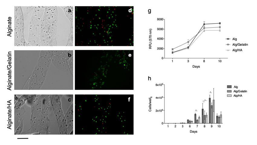
Bioengineering 2019, 6, 30                                                                            2 of 13

importantly, biological cues can be easily incorporated to be locally released, and to support tissue
development [9,10]. Furthermore, as cells are incorporated during scaffold formation, obtaining a
uniform distribution throughout the material is generally effortless.
       Nonetheless, when injectable formulations are used for in situ hydrogel formation, an inability
to provide functional vascularization at the time of implantation significantly limits the volume
of deliverable material. The thickness of the constructs, in fact, is substantially limited to in vivo
oxygen, nutrient, and waste diffusion. Although this value significantly depends on the material,
microstructures, and the implant site, it generally ranges over a few hundreds of microns, as most
hydrogels possess only a nano-scaled porosity [11,12].
       To sustain the in vivo survival of encapsulated cells, methods to introduce a higher scale porosity
in hydrogels include porogen leaching [13], freeze-drying [14], gas-foaming [15], and rapid prototyping
techniques [16]. Due to the presence of potentially detrimental chemicals, or of processing conditions
(i.e., temperature and pressure) that are incompatible with cell survival, only a subset of these
techniques are practicable when embedded cells are involved. Particulate leaching is among them
for selected porogen chemistries, but it has the disadvantage of mainly creating a network of isolated
pores. On the contrary, a rapid prototyping technique allows for the creation of complex structures for
the organization of tissues and organs [17,18] but, in turn, this requires more complex equipment and
fabrication processes.
       An interesting possibility for create larger porosities is represented by the fabrication of scaffolds
from opportunely assembled hydrogel fibers, where pores are created as spaces between the assembled
fibers [19]. Methods that are currently available to prepare hydrogel fibers include 3D-printing [20–22],
microfluidic devices [23–25], and extrusion [26]. While 3D-printing allows for the fabrication of
homogeneous fibers over a range of 500 µm, and requires specific equipment, microfluidic channels
allow for even smaller fibers (150–500 µm [27]) to be precisely obtained, but with lower yield.
The extrusion method, on the other hand, represents the simplest technique for microfiber formation,
and involves the injection of a precursor solution into a gelator solution. This fabrication technique
is mainly employed to produce continuous single-standing fibers for cell encapsulation [26,28],
and mainly relies on the use of sodium alginate and its mild gelation mechanism (room temperature,
close to neutral pH) in the presence of divalent cations [29]. Despite its recognized advantages in terms
of general biocompatibility and non-immunogenicity, the lack of specific binding sites in alginate
for cell adhesion means that it cannot be metabolically dealt with, and the high molecular weight
residues are too large for renal clearing. For this reason, chemical modification (e.g., oxidation, or RDG
coupling) [30] and blending with cell-interactive components are common strategies [23,31–34].
       Although technologies for hydrogel fiber production have been available for a while, their uses in
3D scaffold have had very limited practical applications, with exceptions being made for 3D-printed
structures, that however, are frequently limited in terms of lower fiber dimension.
       Here, we proposed a new, extremely simple extrusion system based on coaxial flow, designed to
encapsulate cells into self-standing hydrogel patches with controlled fiber diameters. To the best of
our knowledge, no previous attempts have been made to control fiber diameters by coaxial-flow in
non-microfluidic devices [35], or to fabricate self-standing, cell-loaded scaffolds.
       As the possibility for exploiting this system within different applications relies on the possibility
of tuning the chemical composition and properties, blends with common biological macromolecules
(gelatin and hyaluronic acid) were also processed to patches, to demonstrate the versatility of this
fabrication strategy.

2. Materials and Methods

2.1. Materials
     All chemicals, if not otherwise stated, were purchased from Sigma-Aldrich, and used without
further treatment.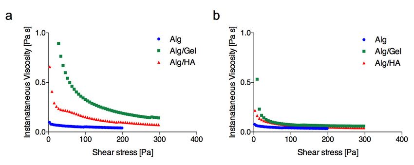
Bioengineering 2019, 6, 30 3 of 13
2.2. Design of a Coaxial-Flow Fabrication Circuit
The circuit that was designed for the preparation of continuous alginate microfibers is illustrated
in Figure 1a. A centrifugal pump (Sicce Syncra 0.5 to 700 L/h, max head 1.2 mt) circulates a CaCl2
solution in a silicon rubber tubing (diameter = 5 mm, thickness = 1 mm) loop. A cell suspension
Bioengineering 2019, 6, x FOR PEER REVIEW 5 of 13
in an alginate solution is injected into the CaCl2 flow through a Y-connector using a syringe pump.
2+
The coaxial flow draws in the alginate solutions and Ca ions crosslinking causes its solidification,
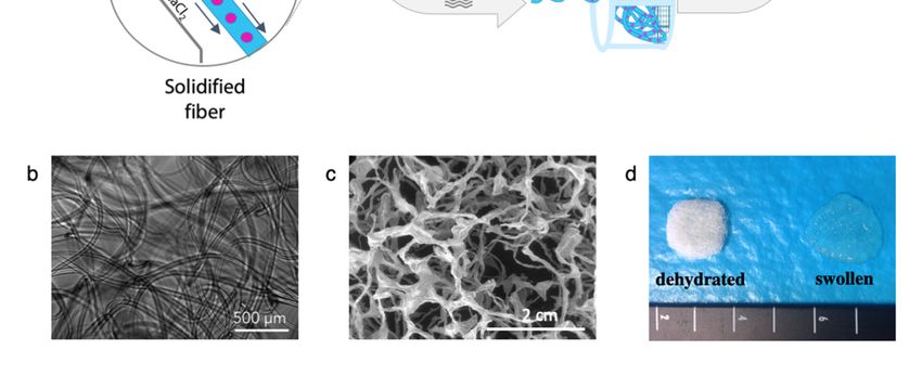
assembled in the strainer as a consistent, self-standing fibrous scaffold, as is shown in Figure 1d,
resulting in a continuous fiber. The fiber whips, bends, and spontaneously assembles in a fibrous patch,
where the appearance of wet and dry microfiber patches is shown.
which can be collected from the strainer.
Figure 1. (a) Schematic representation of microfiber fabrication system. An alginate-based solution is
injected through a syringe pump. The coaxial CaCl2 solution flow draws and solidifies a continuous
Figure
fiber 1. (a)
that Schematicinrepresentation
is collected the strainer asofa microfiber
cell-loadedfabrication system.(b)
hydrogel patch. AnOptical
alginate-based solution
microscope imageis
injected through a syringe pump. The coaxial CaCl2 solution flow draws and solidifies a continuous
of the alginate microfibers, (c) SEM micrograph of the structures of the freeze-dried fibers, and (d)
fiber that is collected
macroscopic in the
appearance strainer
of the as a cell-loaded
microfibers patches inhydrogel patch.states,
their swollen (b) Optical microscope
and after image of
freeze-drying.
the alginate microfibers, (c) SEM micrograph of the structures of the freeze-dried fibers, and (d)
2.3. Plain Alginateappearance
macroscopic Fiber Fabrication and Systempatches
of the microfibers Optimization
in their swollen states, and after freeze-drying.
To prepare the hydrogel fibers, alginic acid sodium salt from brown algae (viscosity 15.0–25.0 cP,
With the coaxial flow circuit developed, fibers with diameters ranging from 60 to about 400 μm
Mw = 120–190 kDa) was dissolved in Dulbecco’s Modified Eagle’s Medium (DMEM), and injected in
were obtained in a relatively large range of alginate concentrations (Figure 2a). For each
the circulating CaCl2 solution. To optimize the fabrication process, and evaluate the effect of solution-
concentration, the microfiber diameter was strongly influenced by the syringe pump flow rate, and
and processing-related parameters on fiber formation, the alginate concentration was varied from 1%
as reasonable expected, an increase was observed when the solution feed was raised. Increasing the
to 4% (w/v), and the CaCl2 molarity from 35 to 150 mM, and syringe pump advancing rate from 10 to
alginate concentration had the same effect for up to 2%, but there was a tendency to a decrease in
90 mm/h (1 mm/h, corresponding to 0.3 mL/h). To assess the effects of the syringe needle dimension,
diameters that was observed for the 4% solutions. This finding is probably due to the high viscosity
22, 24, and 26 G diameters were compared for the injection of the alginate solution.
of the 4% solution, which appeared to have hindered the extrusion of the material, as only short
fibers and elongated beads were collected in the strainer. The diameter of the needle also influenced,
as expected, the dimensions of the microfibers (Figure 2b). A significant difference in fiber
dimensions when using the 22 G or 26 G needle was observed for each pumping flow rate, except for
70 mm/hr.
Fibers generally appeared homogeneous in diameter and smooth in their surface, except for
some combinations with low CaCl2 flow rates (Figure 2c) and low alginate flow rates (10–30 mm/hr,
Figure 2d), where the fiber surfaces appeared wrinkled.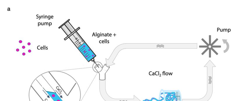
Bioengineering 2019, 6, 30                                                                            4 of 13

     For each set of parameters, the extruded fibers were retrieved from the strainer, and their
morphologies were evaluated by optical microscopy. Quantitative analyses on fiber diameter were
performed on acquired images, using the image-processing software ImageJ [36], based on 30 different
measures in random points from at least three different images.

2.4. Alginate-Blended Microfiber Production
     To confirm the possibility of creating scaffolds from different compositions, two biological
macromolecules were blended with 2% (w/v) alginate. Gelatin (from porcine skin, Type A) and
hyaluronic acid sodium salt (HA, from Streptococcus equi, Mw = 1.5–1.8 × 10⁶ g/mol) were blended in
at the ratios in Table 1, and processed with the flow circuit, to fabricate microfibers patches.

                             Table 1. Composition of blends for microfibers patch fabrication.

                                                           Final Concentrations (% w/v)
                         Sample Label
                                                Alginate      Gelatin     Hyaluronic Acid (HA)
                                Alg                 2             -                  -
                                                                 0.5
                             Alg/Gelatin            2            1.5                 -
                                                                  3
                                                                                    0.1
                              Alg/HA                2             -
                                                                                    0.2

2.5. Rheological Properties
     Rheological properties of hydrogel-forming solutions are critical for fiber formation, and hence,
they were evaluated using a CVO 120 stress-controlled Rotational Rheometer (Bohlin Instruments,
cone/plate geometry with cone diameter = 40 mm and cone angle = 1◦ ). The gap was automatically
set to 0.03 mm. A Peltier plate was used to thermostat the solutions at 25 or 37 ◦ C. Steady shear
measurements were performed by increasing the shear stress from zero to a maximum of 300 Pa.

2.6. Swelling and Weight Loss
       Swelling and weight loss of microfibers at 37 ◦ C in phosphate buffer saline (PBS), or in complete
cell culture medium were evaluated for up to 21 days, to appraise their kinetics. At selected time-points
(1, 2, 3, 5, 7, 24, 48, 72 h, and 7, 14, 21 days), microfibers were strained from the medium, centrifuged to
eliminate the excess of water, and weighted with a precision balance. The weight variation (∆W%)
was calculated as:
                                           ∆W% = [(Wt − W0 )/W0 ]100,                                    (1)

where Wt is the measured weight of a swollen sample at time t and W0 its initial weight.
     To increase the stability of the fibers, two different methods were investigated: (i) a post-treatment
of fibers in high molarity CaCl2 solution (150 mM) for 5 min, and (ii) a combination of external
and internal alginate gelation. In this latter case, 5 mM CaCO3 was mixed with the cell suspension,
and fibers were treated in D-gluconic acid-δ-lactone (GDL, 5 mM, pH 3.4) solution for five seconds.

2.7. Cells Encapsulation in Microfibers
     For cell experiments, a CaCl2 solution was sterile-filtered (0.2 µm), sodium alginate and gelatin
powders were disinfected by soaking in ethanol and HA powder, and all of the flow-loop components
were sterilized by autoclaving.
     Murine cells L929 (ATCC CCL-1) were detached from flasks with trypsin-EDTA
(ethylenediaminetetraacetic acid) when reaching 90% confluence, and they were resuspended
(1.5 × 10⁶ cells/mL) in alginate or blended solutions prepared in DMEM.
Bioengineering 2019, 6, 30 5 of 13
After fabrication, cell-loaded patches were placed in cell strainers and cultured in a 12-well
multiwell plate with DMEM, supplemented with 10% (v/v) fetal bovine serum (FBS) with 1%
penicillin/streptomycin at 37 ◦ C and 5% CO2 .
2.8. Evaluation of Cell Viability
Cell survival immediately after encapsulation was investigated by double staining with propidium
iodide (20 µM) and calcein-AM (2 µM) in a serum-free cell culture medium. After rinsing in
PBS, samples were incubated in the staining solution at 37 ◦ C for 40 min and rinsed again before
imaging. Fluorescence images were acquired by using a Zeiss Axioplan microscope, using 490/515 nm
(excitation/emission) filters for calcein-AM, and 535/617 nm (excitation/emission) for propidium
iodide. ImageJ [36] image processing software was used to merge the images and count cells.
Longer-term viability of embedded cells in alginate-based fibers was measured after 1, 3, 8,
and 10 days, using an Alamar Blue® assay according to the manufacturer’s indications.
2.9. In Vitro Cell Release
The number of cells released from the alginate-based patches was estimated by acquiring daily
microscopic images of the bottom of the wells, and counting cells in five randomly selected areas
(0.7 mm2 ). To evaluate the progression of cell release, strainers containing patches were moved daily
to a new plate, in order to account only for cells released in the previous 24 h.
2.10. Statistical Analysis
Results are presented as mean ± standard deviation (SD). Statistical analyses were performed
using GraphPad Prism software (GraphPad Software Inc., version 6). Statistically significant differences
were determined by one-way analysis of variance (ANOVA), followed by Tukey’s post-test for pairwise
comparisons, and p < 0.05 was considered statistically significant.
3. Results and Discussion
3.1. Plain Alginate Microfiber Fabrication and System Optimization
The injection of alginate-based solutions in a circulating CaCl2 bath was confirmed to be an easy
and effective method of preparing alginate-based microfibers, and it proved the effectiveness of the
designed flow circuit, as schematized in Figure 1a. For most sets of parameters tested, a continuous
fiber was extruded (Figure 1b,c) and, more interestingly, in a subset of cases, it was spontaneously
assembled in the strainer as a consistent, self-standing fibrous scaffold, as is shown in Figure 1d,
where the appearance of wet and dry microfiber patches is shown.
With the coaxial flow circuit developed, fibers with diameters ranging from 60 to about 400 µm
were obtained in a relatively large range of alginate concentrations (Figure 2a). For each concentration,
the microfiber diameter was strongly influenced by the syringe pump flow rate, and as reasonable
expected, an increase was observed when the solution feed was raised. Increasing the alginate
concentration had the same effect for up to 2%, but there was a tendency to a decrease in diameters
that was observed for the 4% solutions. This finding is probably due to the high viscosity of the 4%
solution, which appeared to have hindered the extrusion of the material, as only short fibers and
elongated beads were collected in the strainer. The diameter of the needle also influenced, as expected,
the dimensions of the microfibers (Figure 2b). A significant difference in fiber dimensions when using
the 22 G or 26 G needle was observed for each pumping flow rate, except for 70 mm/h.Bioengineering 2019, 6, 30
x FOR PEER REVIEW 66of
of 13
Figure 2. (a) Effect of alginate concentration and syringe pump flow rate on fiber dimensions. (b) Effect
of needle
Figure 2. dimension onalginate
(a) Effect of fiber diameter (* p < 0.05,
concentration p < 0.01,pump
and**syringe *** phave proceeded too far as they reach the strainer, because this allows further crosslinking to involve
molecules from different fibers, and create strong adhesions among them. For this reason, a low
concentration of crosslinking ions and a short permanence in the flow before the collection will
result in self-standing, easy-to-handle patches.
The use of a coaxial flow in a non-microfluidic device allows for the production of fiber
Bioengineering 2019, 6, 30 7 of 13
diameters that are comparable to those obtained in microfluidic devices (150–500 μm [27]), but with
a processing speed that is one order of magnitude higher (0.5 mL/min versus 50 μL/min typically
ions in the
observed in external
microfluidicalginate shell[27]).
devices at theFurthermore,
time of collection. As ascaffolds
cohesive result, non-consistent
are prepared withinand extremely
a very
difficult-to-handle
short time, for the structures
benefit of were retrieved,with
cell survival, and 35a mM was chosen
one-step for the
procedure, production
avoiding the of continuous
need for an
microfibers
additional andthat
step coherent, consistent
is required scaffolds.discrete fibers that are produced in similar systems
to assemble
Results suggest that an effective adhesion between fibers requires crosslinking that should not
[24,37–39].
have proceeded too far as they reach the strainer, because this allows further crosslinking to involve
3.2. Blended Microfiber
molecules from differentFabrication
fibers, and create strong adhesions among them. For this reason, a low
concentration
The addition of gelatin ions
of crosslinking or HA,and asa short permanence
qualitatively shownin theinflow before
Figure 3d,the
didcollection will fiber
not inhibit result
in self-standing,
formation, neithereasy-to-handle
did it affect thepatches.
general morphology of the microfibers. In the case of gelatin, even
The use of a coaxial
when its proportion in the flow in a was
blend non-microfluidic
higher than device
alginateallows
(3% vsfor2%)
the production
smooth and ofhomogeneous
fiber diameters
that are comparable
fibers were obtained. to those obtained in microfluidic devices (150–500 µm [27]), but with a processing
speed thatincreasing
When is one order of magnitude
solution flow rate, higher (0.5 mL/min
the trend versus
in microfiber 50 µL/min
diameter typically
for blends wasobserved
consistentin
with that observed for pure alginate, but the introduction of gelatin into the polymershort
microfluidic devices [27]). Furthermore, cohesive scaffolds are prepared within a very time,
solution
for the benefit of cell survival, with a one-step procedure, avoiding the need for
determined a significant increase of microfiber diameter for all flow rates and concentrations (Figurean additional step that
is required
3a,b). to assemble
This finding discrete fibers
is consistent with an thatincrease
are produced in similar
in solution systems
viscosity, as [24,37–39].
revealed by rheological
measurements (Figure 4a), imputable to the increased overall concentration of the solution.
3.2. Blended Microfiber Fabrication
Contrarily, HA did not have the same effect at both of the concentrations chosen for blending
(0.1% The
andaddition
0.2% (w/v),of gelatin
Figureor3c)
HA,[40,41].
as qualitatively
Due to theshown
highinmolecular
Figure 3d,weight,
did not HA
inhibit
was fiber formation,
added in at
neither did it affect the general morphology of the microfibers. In the case of gelatin,
lower percentages, and the increase in viscosity at room temperature was less pronounced (Figure even when
its
4a). proportion in the blend was higher than alginate (3% vs. 2%) smooth and homogeneous fibers
were obtained.
Figure 3. Effects of different parameters on fiber dimensions. (a) Effects of solution composition and
solution flow rates. Effect of blend components on fiber diameters: for (b) gelatin and (c) HA blends.
Figure 3. Effects of different parameters on fiber dimensions. (a) Effects of solution composition and
(d) Optical images of alginate, alginate/gelatin, and alginate/HA microfibers. Scale bar = 200 µm.
solution flow rates. Effect of blend components on fiber diameters: for (b) gelatin and (c) HA blends.
(* p < 0.05, ** p < 0.01 and *** p < 0.005).
When increasing solution flow rate, the trend in microfiber diameter for blends was consistent
with that observed for pure alginate, but the introduction of gelatin into the polymer solution
determined a significant increase of microfiber diameter for all flow rates and concentrations
(Figure 3a,b). This finding is consistent with an increase in solution viscosity, as revealed by rheological
measurements (Figure 4a), imputable to the increased overall concentration of the solution.< 0.05, ** p < 0.01 and *** p < 0.005).
Rheological measurements (Figure 4) also showed a distinct influence of temperature on the
viscosity changes in both blends. While the alginate curve was substantially unchanged, the addition
of both gelatin and HA caused a substantial increase in the viscosity at room temperature, while the
effect was
Bioengineering 2019,significantly
6, 30 less noticeable at 37 °C, where the curves of instantaneous viscosity were8 of 13
largely overlapped (Figure 4b).
Figure 4. Instantaneous viscosity as a function of shear stress for plain alginate (2% w/v) and alginate
blendFigure 4. Instantaneous
solutions (Alg/Gel viscosity as a function
is composed of 2%of(w/v)
shear alginate
stress for plain alginate
and 1.5% (2% w/v)
(w/v) and alginate
gelatin; Alg/HA is
blend solutions (Alg/Gel is composed of 2% (w/v) alginate ◦ and 1.5%◦ (w/v) gelatin; Alg/HA is
composed of 2% (w/v) alginate and 0.2% (w/v) HA) at 25 C (a) and 37 C (b).
composed of 2% (w/v) alginate and 0.2% (w/v) HA) at 25 °C (a) and 37 °C (b).
Contrarily, HA did not have the same effect at both of the concentrations chosen for blending
3.3. Microfiber Swelling and Weight Loss
(0.1% and 0.2% (w/v), Figure 3c) [40,41]. Due to the high molecular weight, HA was added in at lower
percentages,Swelling
and theandincrease
weight loss of microfibers
in viscosity in PBS
at room and in the cell
temperature was culture medium at 37(Figure
less pronounced °C for up to
4a).
21 days are shown in Figure 5. Plain alginate patches (Figure 5a,b) without any further crosslinking
Rheological measurements (Figure 4) also showed a distinct influence of temperature on the
lost the majority of their weights within the first 48 h.
viscosity changes in both blends. While the alginate curve was substantially unchanged, the addition
Based on the rapidity of weight loss and the degree of swelling, it is reasonable to assume that,
of both gelatin and HA caused a substantial increase in the viscosity at room temperature, while the
due to the low concentration of CaCl2 a weakly cross-linked shell forms around a nearly liquid core
effect[42].
wasAs significantly lessbecause
the shell breaks noticeable at 37 ◦ C, stress
of mechanical wherecaused
the curves of instantaneous
by swelling, the release ofviscosity
the liquidwere
largely overlapped
core accounts for(Figure 4b).weight loss. Accordingly, when CaCO3 is added to the alginate solution
the steep
to create a denser core, a higher persistence of fibers is observed, and the greatest weight loss takes
3.3. Microfiber Swelling
place between and14Weight
7 and days. Loss
When the patches underwent a post treatment by immersion in
concentratedandCaCl
Bioengineering 2019,
Swelling solution
6, 2x FOR
weight of(150
PEER REVIEW
loss mM), a in
microfibers considerably
PBS and inhigher PBS
the cell stability
culture was observed,
medium andup to
at 379◦ofC13for
swelling was still prevailing over degradation after 14 days. This large delay in swelling is likely to
21 dayschain
are shown in Figure 5. Plain alginate patches (Figure 5a,b)egg-box-forming
without any further crosslinking
be due torelaxation
both a denser favors(inswelling, while
shell) and degradation
deeper (in core,begins
for thewhen
higher Ca2+ amount
chemical gradient) ions in of
lost thepolyguluronate
majority of their weights within the first 48
blocks start to exchange with Na [44].
+ h.
crosslinking. In this case, in fact, no relevant effects of calcium carbonate appeared.
The effects of post-treatment in a high molarity CaCl2 solution also had an important effect on
the adhesion between fibers, as patches were more consolidated and resistant to handling. For this
latter reason, together with it being less of a threat for cell viability (compared to internal gelation),
this method was preferred for its increased fiber stability.
Interestingly, a very different mode of behavior was observed when post-treated patches were
aged in complete medium (Figure 5b). Here, alginate patches lost a considerable percent of their
weight (around 30%) within the first hour. After this initial contraction, a weight increase was
observed for up to 7 days, followed by a progressive loss. As the swelling of ionic gels is controlled
by the osmotic pressure in the gel and the elastic reaction of its network [43], it is not surprising to
observe different behaviors in volume change after its immersion in solutions with different ionic
strengths. In calcium alginate gels, in particular, swelling and degradation are regulated on an
exchange mechanism between cross-linked Ca2+ ions and Na+ ions in the ageing media. When this
exchange involves Ca2+ that are bound to COO− groups of polymannuronate blocks, the resulting
Figure 5. Percentage weight variation after ageing in (a) Phosphate Buffer Saline (PBS) and in (b)
Figure
Dulbecco’s 5. Percentage
Modified weight
Eagle’s variation
Medium after ageing
(DMEM) for in (a) Phosphate
microfibers Buffer Saline
prepared with(PBS) and in (b)solution,
2% alginate
Dulbecco’s Modified Eagle’s Medium (DMEM) for microfibers prepared with 2% alginate solution,
50 mm/h flow rate, and a 24 G needle. (c) Percentage weight variation after ageing in DMEM for
50 mm/hr flow rate, and a 24 G needle. (c) Percentage weight variation after ageing in DMEM for
alginate-blended microfibers prepared with a 2% alginate solution blended with 1.5% gelatin or 0.2%
alginate-blended microfibers prepared with a 2% alginate solution blended with 1.5% gelatin or 0.2%
HA (* pHA
< 0.05, pBioengineering 2019, 6, 30 9 of 13
Based on the rapidity of weight loss and the degree of swelling, it is reasonable to assume that, due
to the low concentration of CaCl2 a weakly cross-linked shell forms around a nearly liquid core [42].
As the shell breaks because of mechanical stress caused by swelling, the release of the liquid core
accounts for the steep weight loss. Accordingly, when CaCO3 is added to the alginate solution to
create a denser core, a higher persistence of fibers is observed, and the greatest weight loss takes place
between 7 and 14 days. When the patches underwent a post treatment by immersion in concentrated
CaCl2 solution (150 mM), a considerably higher PBS stability was observed, and swelling was still
prevailing over degradation after 14 days. This large delay in swelling is likely to be due to both a
denser (in shell) and deeper (in core, for the higher chemical gradient) amount of crosslinking. In this
case, in fact, no relevant effects of calcium carbonate appeared.
The effects of post-treatment in a high molarity CaCl2 solution also had an important effect on
the adhesion between fibers, as patches were more consolidated and resistant to handling. For this
latter reason, together with it being less of a threat for cell viability (compared to internal gelation),
this method was preferred for its increased fiber stability.
Interestingly, a very different mode of behavior was observed when post-treated patches were
aged in complete medium (Figure 5b). Here, alginate patches lost a considerable percent of their weight
(around 30%) within the first hour. After this initial contraction, a weight increase was observed for up
to 7 days, followed by a progressive loss. As the swelling of ionic gels is controlled by the osmotic
pressure in the gel and the elastic reaction of its network [43], it is not surprising to observe different
behaviors in volume change after its immersion in solutions with different ionic strengths. In calcium
alginate gels, in particular, swelling and degradation are regulated on an exchange mechanism between
cross-linked Ca2+ ions and Na+ ions in the ageing media. When this exchange involves Ca2+ that are
bound to COO− groups of polymannuronate blocks, the resulting chain relaxation favors swelling,
while degradation begins when egg-box-forming Ca2+ ions in polyguluronate blocks start to exchange
with Na+ [44].
Accordingly, the different behaviors in swelling and weight loss in PBS and the complete media
can be explained by the differences in the types and concentrations of the solutes. As the difference in
weight loss stands out when comparing the results in Figure 5a,b, its implications for the cell release
profiles should be taken into account.
In Figure 5c, the swelling profile of blended hydrogel is shown. As observed in plain alginate
samples, a significant degree of weight loss (around 30%) was measured within the first few hours of
incubation, for the three types of microfibers (alginate, alginate/gelatin 1.5% and alginate/HA 0.2%).
After this initial contraction, the alginate microfibers started to swell, and they increased in weight
for up to 7 days, and they decreased again thereafter, to reveal a progressive dissolution of fibers.
Although it occurred to different extents, the sequence of contraction, swelling, and dissolution was
observed for all types of microfibers.
3.4. Cell Encapsulation in Alginate Microfibers
Microfibers for cell embedding were produced using a 2% (w/v) alginate solution with the
addition of 1.5% (w/v) or 0.2% (w/v) of gelatin and HA, respectively. Under these conditions,
embedded cells were distributed as single cells uniformly along the microfibers, as shown in the
optical micrographs (Figure 6a–c).
According to staining that was performed shortly after encapsulation (Figure 6d–f), the process
allows for a good degree of viability to be preserved in all materials (75 ± 16% for alginate/gelatin
blend, 71 ± 6% for alginate/HA blend and 79 ± 6% for plain alginate).
Over longer time spans, alginate-based microfibers were also confirmed to offer an adequate
environment for the survival of embedded cells, as demonstrated from Alamar Blue® results (Figure 6g).
A progressive increase in fluorescence intensity is observed until day 8, but this is unchanged at the
following time point. If this result is compared with the cell release profile (Figure 6h), it can be noticed
that a large number of cells are actually released between day 8 and 10. As a consequence, proliferationBioengineering 2019, 6, 30 10 of 13
and Alamar Blue® reduction rely only on a lower number of cells. For all of the formulations,
the released cells
Bioengineering 2019,appeared toREVIEW
6, x FOR PEER be viable, and they were well-adhered to the bottom of the13 well
10 of
(Supplementary materials—Figure S2).
Figure 6. White light (a–c) and fluorescence (d–f) micrographs of fibroblast-loaded microfibers.
Figure 6.images
Fluorescence White light
were(a, b, c) shortly
taken and fluorescence (d, e, f) micrographs
after embedding of with
and staining, fibroblast-loaded
calcein-AMmicrofibers.
and propidium
Fluorescence
iodide. Scale bar =images
200 µm. were taken shortly
Evaluation after
of L929 embedding
fibroblast and staining,
behavior with calcein-AM
after embedding and and
in alginate
propidium
blended iodide.(g)
microfibers: Scale
Alamar 200 μm.
bar = Blue Evaluation of
® fluorescence L929 fibroblast
intensities behavior
and (h) after embedding
the number in
of cells released
alginate and blended microfibers: (g) Alamar Blue® fluorescence intensities and (h) the number of
from the microfibers.
cells released from the microfibers.
4. Conclusions
Over longer time spans, alginate-based microfibers were also confirmed to offer an adequate
Designing
environment a for
hydrogel scaffold
the survival for the incells,
of embedded situasrelease of embedded
demonstrated cells raises
from Alamar many (Figure
Blue® results challenges,
especially
6g). Ain terms of the
progressive compatibility
increase of theintensity
in fluorescence fabrication with cell
is observed untilsurvival,
day 8, but adequate mass exchange,
this is unchanged at
the following time point. If this result is compared with the cell release
and the tuning of degradation profiles. For some types, however, the fiber-encapsulation system thatprofile (Figure 6h), it can be
noticed
has been that a large
designed in thisnumber
work of cells are
appears toactually released
offer some between
effective day 8 and 10. As a consequence,
solutions.
proliferation and Alamar Blue ® reduction rely only on a lower number of cells. For all of the
Despite its simplicity (it can be built in a short period time, with readily available, inexpensive
formulations, the released cells appeared to be viable, and they were well-adhered to the bottom of
components), the system that has been designed in this study allows for the rapid (about 3 min)
the well (Supplementary materials—Figure S2).
fabrication of large, cell-loaded fibrous scaffolds. The distribution of cells is very regular and
homogenous within the fibers and throughout the scaffold. Furthermore, the two-step crosslinking
4. Conclusions
process, by consolidating bonding between the fibers, results in cohesive, easy-to-handle scaffolds.
Designing a hydrogel scaffold for the in situ release of embedded cells raises many challenges,
In the fibrous patch, only a thin layer of material separates the cells from the environment, and a
especially in terms of the compatibility of the fabrication with cell survival, adequate mass exchange,
uniformand network
the tuningof of macro-pores is created
degradation profiles. in the
For some structure
types, however,as the
thefiber-encapsulation
fibers assemble. system This favorable
that
architecture, according to the viability results, appears to be
has been designed in this work appears to offer some effective solutions. a large benefit in terms of mass-exchange
and cell survival, compared
Despite its simplicityto(itbulk
can behydrogels.
built in a short period time, with readily available, inexpensive
In addition, the
components), the flow-circuit
system that has system demonstrated
been designed in this astudy
significant
allows for degree of flexibility
the rapid in terms
(about 3 min)
fabrication
of material of large, cell-loaded
composition, fibrous scaffolds.
as fiber formation was possibleThe distribution
for a relatively of cells
large is very
rangeregular and
of parameters.
homogenous
As plain within not
alginate might the fibers
always and throughout
represent the the scaffold.
ideal materialFurthermore,
[45], blendingthe two-step crosslinking
fiber-forming alginates
process,
with other by consolidating
molecules bonding between
or macromolecules the fibers,
appears to beresults in cohesive, option
an interesting easy-to-handle scaffolds.
for reducing alginate
In the fibrous patch, only a thin layer of material separates the cells from the environment, and
quantities in favor of metabolically degradable components, instructions for cell behavior or tuning for
a uniform network of macro-pores is created in the structure as the fibers assemble. This favorable
cell release [42].
architecture, according to the viability results, appears to be a large benefit in terms of
For all of the above-mentioned
mass-exchange reasons, the
and cell survival, compared developed
to bulk hydrogels.fiber-encapsulating system appears to be a
very powerful platform for in vivo cell delivery in regenerative
In addition, the flow-circuit system demonstrated a significant medicine,
degree ofbut also, more
flexibility generally,
in terms of
for inmaterial
vitro cellcomposition,
culturing. For this formation
as fiber latter technique in particular,
was possible a simple,
for a relatively widely
large rangeavailable and effective
of parameters. As
technique
plain for preparing
alginate might effective
not always cell-loaded
represent thescaffolds is highly
ideal material desirable,
[45], blending as it representalginates
fiber-forming an essential
tool inwith
the other moleculesof
development or3Dmacromolecules
cell cultures and appears
more to reliable
be an interesting
in vitro modelsoption for
forreducing alginate
many applications.Bioengineering 2019, 6, 30 11 of 13
Supplementary Materials: The following are available online at http://www.mdpi.com/2306-5354/6/2/30/s1,
Figure S1: Effect of CaCl2 flow rate on microfiber diameter, Figure S2: cells released from microfibers at the bottom
of the cell culture wells.
Author Contributions: Conceptualization, F.C. and L.D.; methodology, C.E.C., F.C. and L.D.; formal analysis,
C.E.C., F.C. and L.D.; investigation, F.C. and C.E.C.; supervision, L.D.; writing—original draft, C.E.C. and F.C.;
Writing—review & editing, C.E.C. and L.D.
Funding: No financial support was received for this research.
Acknowledgments: The authors gratefully acknowledge Gigliola “Gilly” Clerici for her support in
rheological testing.
Conflicts of Interest: The authors declare no conflict of interest.
References
1. Bayoussef, Z.; Dixon, J.E.; Stolnik, S.; Shakesheff, K.M. Aggregation promotes cell viability, proliferation,
and differentiation in an in vitro model of injection cell therapy. J. Tissue Eng. Regen. Med. 2012, 6, e61–e73.
[CrossRef] [PubMed]
2. Mooney, D.J.; VanDenburgh, H. Cell Delivery Mechanisms for Tissue Repair. Cell Stem Cell 2008, 2, 205–213.
[CrossRef] [PubMed]
3. Tang, J.; Cui, X.; Caranasos, T.G.; Hensley, M.T.; Vandergriff, A.C.; Hartanto, Y.; Shen, D.; Zhang, H.; Zhang, J.;
Cheng, K. Heart Repair Using Nanogel-Encapsulated Human Cardiac Stem Cells in Mice and Pigs with
Myocardial Infarction. ACS Nano 2017, 11, 9738–9749. [CrossRef]
4. Ding, K.; Yang, Z.; Zhang, Y.-L.; Xu, J.-Z. Injectable thermosensitive chitosan/β-glycerophosphate/collagen
hydrogel maintains the plasticity of skeletal muscle satellite cells and supports their in vivo viability.
Cell Boil. Int. 2013, 37, 977–987. [CrossRef]
5. Richards, M.; Huibregtse, B.A.; Caplan, A.I.; Goulet, J.A.; Goldstein, S.A. Marrow-derived progenitor cell
injections enhance new bone formation during distraction. J. Orthop. Res. 1999, 17, 900–908. [CrossRef]
[PubMed]
6. Ku, M.; Yang, J.; Ko, Y.; Kim, H.-Y.; Kim, D.; You, J.; Lee, C.; Jeong, H.Y.; Kwon, G.; Yamauchi, Y.; et al.
Antibacterial poly (3,4-ethylenedioxythiophene):poly(styrene-sulfonate)/agarose nanocomposite hydrogels
with thermo-processability and self-healing. Carbohydr. Polym. 2018, 203, 26–34.
7. Hollister, S.J. Porous scaffold design for tissue engineering. Nat. Mater. 2005, 4, 518–524. [CrossRef]
8. Zhang, Z.; Eyster, T.W.; Ma, P.X. Nanostructured injectable cell microcarriers for tissue regeneration.
Nanomedicine 2016, 11, 1611–1628. [CrossRef] [PubMed]
9. Nicodemus, G.D.; Bryant, S.J. Cell Encapsulation in Biodegradable Hydrogels for Tissue Engineering
Applications. Eng. B Rev. 2008, 14, 149–165. [CrossRef]
10. Lu, H.D.; Charati, M.B.; Kim, I.L.; Burdick, J.A. Injectable shear-thinning hydrogels engineered with a
self-assembling Dock-and-Lock mechanism. Biomaterials 2012, 33, 2145–2153. [CrossRef]
11. Benavides, O.M.; Brooks, A.R.; Cho, S.; Connell, J.P.; Ruano, R.; Jacot, J.G.; Cho, S.K. In situ vascularization
of injectable fibrin/poly(ethylene glycol) hydrogels by human amniotic fluid-derived stem cells. J. Biomed.
Mater. Res. A 2015, 103, 2645–2653. [CrossRef]
12. Li, R.H.; Altreuter, D.H.; Gentile, F.T. Transport characterization of hydrogel matrices for cell encapsulation.
Biotechnol. Bioeng. 1996, 50, 365–373. [CrossRef]
13. Samaryk, V.; Voronov, A.; Tarnavchyk, I.; Kohut, A.; Nosova, N.; Varvarenko, S.; Voronov, S. A versatile
approach to develop porous hydrogels with a regular pore distribution and investigation of their
physicomechanical properties. J. Appl. Polym. Sci. 2009, 114, 2204–2212. [CrossRef]
14. Patel, V.R.; Amiji, M.M. Preparation and Characterization of Freeze-dried Chitosan-Poly(Ethylene Oxide)
Hydrogels for Site-Specific Antibiotic Delivery in the Stomach. Pharm. Res. 1996, 13, 588–593. [CrossRef]
15. Barbetta, A.; Rizzitelli, G.; Bedini, R.; Pecci, R.; Dentini, M. Porous gelatin hydrogels by gas-in-liquid foam
templating. Soft Matter 2010, 6, 1785. [CrossRef]
16. Billiet, T.; Vandenhaute, M.; Schelfhout, J.; Van Vlierberghe, S.; Dubruel, P. A review of trends and limitations
in hydrogel-rapid prototyping for tissue engineering. Biomaterials 2012, 33, 6020–6041. [CrossRef] [PubMed]
17. Cui, X.; Breitenkamp, K.; Finn, M.; Lotz, M.; D’Lima, D.D. Direct Human Cartilage Repair Using
Three-Dimensional Bioprinting Technology. Eng. A 2012, 18, 1304–1312. [CrossRef]Bioengineering 2019, 6, 30 12 of 13
18. Duan, B.; Hockaday, L.A.; Kang, K.H.; Butcher, J.T. 3D bioprinting of heterogeneous aortic valve conduits
with alginate/gelatin hydrogels. J. Biomed. Mater. Res. Part A 2013, 101, 1255–1264. [CrossRef] [PubMed]
19. Onoe, H.; Takeuchi, S. Cell-laden microfibers for bottom-up tissue engineering. Drug Discov. 2015, 20,
236–246. [CrossRef]
20. Lin, H.Y.; Peng, C.W.; Wu, W.W. Fibrous hydrogel scaffolds with cells embedded in the fibers as a potential
tissue scaffold for skin repair. J. Mater. Sci. Mater. Med. 2014, 25, 259–269. [CrossRef]
21. Ghorbanian, S.; Qasaimeh, M.A.; Akbari, M.; Tamayol, A.; Juncker, D. Microfluidic direct writer with
integrated declogging mechanism for fabricating cell-laden hydrogel constructs. Biomed. Microdevices 2014,
16, 387–395. [CrossRef] [PubMed]
22. Negrini, N.C.; Bonetti, L.; Contili, L.; Farè, S. 3D printing of methylcellulose-based hydrogels. Bioprinting
2018, 10, e00024. [CrossRef]
23. Angelozzi, M.; Miotto, M.; Penolazzi, L.; Mazzitelli, S.; Keane, T.; Badylak, S.F.; Piva, R.; Nastruzzi, C.
Composite ECM–alginate microfibers produced by microfluidics as scaffolds with biomineralization
potential. Mater. Sci. Eng. C 2015, 56, 141–153. [CrossRef] [PubMed]
24. Shin, S.-J.; Park, J.-Y.; Lee, J.-Y.; Park, H.; Park, Y.-D.; Lee, K.-B.; Whang, C.-M.; Lee, S.-H. “On the Fly”
Continuous Generation of Alginate Fibers Using a Microfluidic Device. Langmuir 2007, 23, 9104–9108.
[CrossRef]
25. Mazzitelli, S.; Capretto, L.; Carugo, D.; Zhang, X.; Piva, R.; Nastruzzi, C. Optimised production of
multifunctional microfibres by microfluidic chip technology for tissue engineering applications. Lab Chip
2011, 11, 1776. [CrossRef]
26. Song, Y.; Zhang, C.; Wang, P.; Wang, L.; Bao, C.; Weir, M.D.; Reynolds, M.A.; Ren, K.; Zhao, L.; Xu, H.H.
Engineering bone regeneration with novel cell-laden hydrogel microfiber-injectable calcium phosphate
scaffold. Mater. Sci. Eng. C 2017, 75, 895–905. [CrossRef]
27. Liu, M.; Zhou, Z.; Chai, Y.; Zhang, S.; Wu, X.; Huang, S.; Su, J.; Jiang, J. Synthesis of cell composite alginate
microfibers by microfluidics with the application potential of small diameter vascular grafts. Biofabrication
2017, 9, 025030. [CrossRef]
28. Sugiura, S.; Oda, T.; Aoyagi, Y.; Satake, M.; Ohkohchi, N.; Nakajima, M. Tubular gel fabrication and cell
encapsulation in laminar flow stream formed by microfabricated nozzle array. Lab Chip 2008, 8, 1255–1257.
[CrossRef]
29. Lee, K.Y.; Mooney, D.J. Alginate: Properties and biomedical applications. Prog. Polym. Sci. 2012, 37, 106–126.
[CrossRef] [PubMed]
30. Bouhadir, K.; Lee, K.; Alsberg, E.; Damm, K.; Anderson, K.; Mooney, D. Degradation of Partially Oxidized
Alginate and Its Potential Application for Tissue Engineering. Biotechnol. Prog. 2001, 17, 945–950. [CrossRef]
31. Mosahebi, A.; Wiberg, M.; Terenghi, G. Addition of Fibronectin to Alginate Matrix Improves Peripheral
Nerve Regeneration in Tissue-Engineered Conduits. Tissue Eng. 2003, 9, 209–218. [CrossRef] [PubMed]
32. Bendtsen, S.T.; Wei, M. Synthesis and characterization of a novel injectable alginate–collagen–hydroxyapatite
hydrogel for bone tissue regeneration. J. Mater. Chem. B 2015, 3, 3081–3090. [CrossRef]
33. Baniasadi, M.; Minary-Jolandan, M.; Zadpoor, A.A. Alginate-Collagen Fibril Composite Hydrogel. Materials
2015, 8, 799–814. [CrossRef]
34. Yao, R.; Zhang, R.; Luan, J.; Lin, F. Alginate and alginate/gelatin microspheres for human adipose-derived
stem cell encapsulation and differentiation. Biofabrication 2012, 4, 025007. [CrossRef] [PubMed]
35. Jun, Y.; Kang, E.; Chae, S.; Lee, S.-H. Microfluidic spinning of micro- and nano-scale fibers for tissue
engineering. Lab Chip 2014, 14, 2145–2160. [CrossRef]
36. A Schneider, C.; Rasband, W.S.; Eliceiri, K.W. NIH Image to ImageJ: 25 years of image analysis. Nat. Chem. Boil.
2012, 9, 671–675. [CrossRef]
37. Furuya, D.C.; da Costa, S.A.; de Oliveira, R.C.; Ferraz, H.G.; Pessoa Junior, A.; Costa, S.M.D. Fibers obtained
from alginate, chitosan and hybrid used in the development of scaffolds. Mater. Res. 2017, 20, 377–386.
[CrossRef]
38. Rinoldi, C.; Costantini, M.; Kijeńska-Gawrońska, E.; Testa, S.; Fornetti, E.; Heljak, M.; Ćwiklińska, M.;
Buda, R.; Baldi, J.; Cannata, S.; et al. Tendon Tissue Engineering: Effects of Mechanical and Biochemical
Stimulation on Stem Cell Alignment on Cell-Laden Hydrogel Yarns. Adv. Healthc. Mater. 2019, 1801218.
[CrossRef] [PubMed]Bioengineering 2019, 6, 30 13 of 13
39. Angelozzi, M.; Penolazzi, L.; Mazzitelli, S.; Lambertini, E.; Lolli, A.; Piva, R.; Nastruzzi, C. Dedifferentiated
Chondrocytes in Composite Microfibers As Tool for Cartilage Repair. Front. Bioeng. Biotechnol. 2017, 5, 35.
[CrossRef]
40. Schmitt, A.; Rödel, P.; Anamur, C.; Seeliger, C.; Imhoff, A.B.; Herbst, E.; Vogt, S.; Van Griensven, M.;
Winter, G.; Engert, J. Calcium Alginate Gels as Stem Cell Matrix—Making Paracrine Stem Cell Activity
Available for Enhanced Healing after Surgery. PLOS ONE 2015, 10, e0118937. [CrossRef]
41. Tu, L.; He, Y.; Yang, H.; Wu, Z.; Yi, L. Preparation and characterization of alginate–gelatin microencapsulated
Bacillus subtilis SL-13 by emulsification/internal gelation. J. Biomater. Sci. Polym. Ed. 2015, 26, 735–749.
[CrossRef] [PubMed]
42. Draghi, L.; Brunelli, D.; Faré, S.; Tanzi, M.C. Programmed cell delivery from biodegradable microcapsules
for tissue repair. J. Biomater. Sci. Polym. Ed. 2015, 26, 1–11. [CrossRef] [PubMed]
43. Moe, S.T.; Skjaak-Braek, G.; Elgsaeter, A.; Smidsroed, O. Swelling of covalently crosslinked alginate gels:
influence of ionic solutes and nonpolar solvents. Macromolecules 1993, 26, 3589–3597. [CrossRef]
44. Bajpai, S.K.; Sharma, S. Investigation of swelling/degradation behaviour of alginate beads crosslinked with
Ca2+ and Ba2+ ions. React. Funct. Polym. 2004, 59, 129–140. [CrossRef]
45. Rowley, J.A.; Madlambayan, G.; Mooney, D.J. Alginate hydrogels as synthetic extracellular matrix materials.
Biomaterials 1999, 20, 45–53. [CrossRef]
© 2019 by the authors. Licensee MDPI, Basel, Switzerland. This article is an open access
article distributed under the terms and conditions of the Creative Commons Attribution
(CC BY) license (http://creativecommons.org/licenses/by/4.0/).You can also read