COMBISTOP type 38 Instruction Manual | Load Brake Size 10 - Original Manual Load Brake Size 10 Document 20243555 000 00 - KEB America
←
→
Page content transcription
If your browser does not render page correctly, please read the page content below
COMBISTOP type 38
Instruction Manual | Load Brake Size 10

                                          Original Manual
                                          Load Brake Size 10
                                          Document 20243555 000 00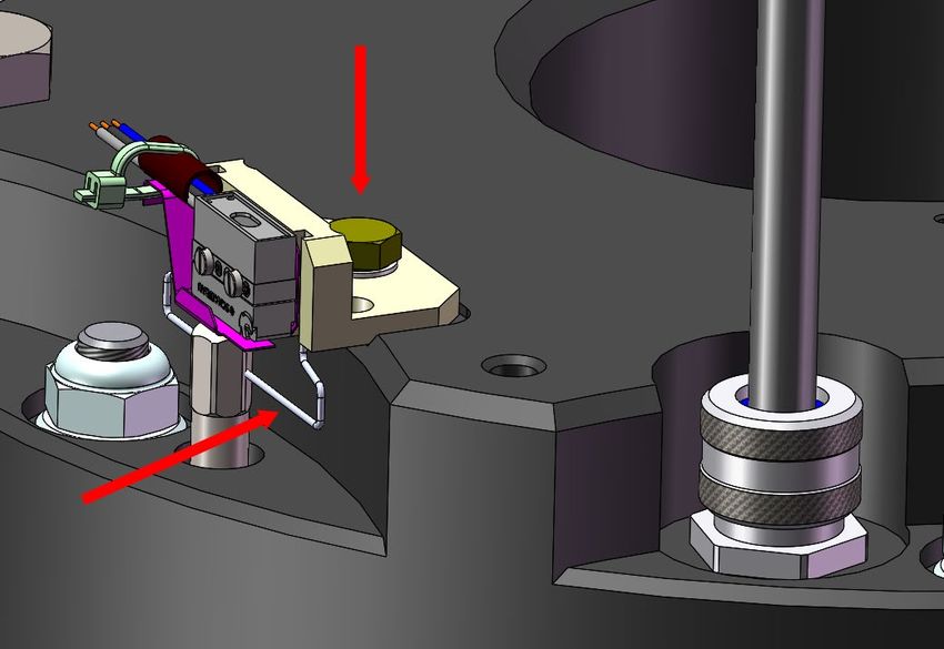
2 © 2021 KEB America, Inc.
Preface
1 Preface
The hardware and software described in this document are products of KEB America,
Inc. The information contained in this document is valid at the time of publishing. KEB
reserves the right to update this document in response to misprints, mistakes or technical
changes.
1.1 Warning Signs and Key Symbols
Certain procedures within this document can cause safety hazards during the installation or
operation of the device. Refer to the safety warnings in this document when performing these
procedures. Safety signs are also located on the device where applicable. A safety warning is
marked by one of the following warning signs:
DANGER Dangerous situation which will cause death or serious injury if this
safety warning is ignored.
WARNING Hazardous situation which may cause death or serious injury if
this safety warning is ignored.
CAUTION Hazardous situation which may cause minor or moderate injury if
this safety warning is ignored.
NOTICE Situation which may cause property damage if this safety warning
is ignored.
RESTRICTION Used when the following statements depend on certain conditions or
are only valid for certain ranges of values.
i Used for informational messages or recommended procedures.
1.2 More Symbols
1. Numbered lists begin action steps.
• Enumerations are marked with dots.
→ Thin arrows indicate cross references to another chapter or another page.
Further documentation can be found at
https://www.kebamerica.com
Document search on www.kebamerica.com/em-
documents/
© 2021 KEB America, Inc. 3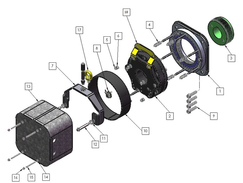
Preface

1.3 Laws and Requirements
            KEB Automation KG has certified the product against the US, Canadian and European
            standards. Additionally KEB Automation KG provides the EC declaration of conformity
            that the product complies with the essential safety requirements.
            The UL, CSA and CE marks are located on the name plate when applicable. The EC
            declaration of conformity can be downloaded on demand via our website.
               →    Further information is provided in Appendix 1: Certification.

1.4 Warranty
            KEB Automation KG provides a limited warranty on all products. This warranty can be
            found in the terms and conditions at our website.

                                 KEB America, Inc. Terms and Conditions
                                                 Terms and Conditions

            Further agreements or specifications require written confirmation from KEB America, Inc.

1.5 Support and Liability
            It is not possible to cover every potential application of our device in a single manual. If
            you require further information or if problems occur which are not covered in this
            document, you can request the necessary information via KEB America, Inc. or the local
            KEB Automation KG agency.
            The use of our products in the target application is beyond our control and
            therefore exclusively the responsibility of the machine manufacturer, system
            integrator or customer.
            The information contained in this document, as well as any user-specific advice in spoken
            or written form or generated through testing, is provided to best of our knowledge and is
            considered for informational purposes only. KEB America, Inc. bears no responsibility or
            liability for the accuracy of the information listed above, nor for any violation of industrial
            property rights committed by a third-party in relation to this information.
            Selection of the most suitable product for any given application is the
            responsibility of the machine manufacturer, system integrator or customer.
            Evaluation of the product can only be performed by the machine manufacturer in
            combination with the application. Any tests performed must be repeated every time any
            part of the hardware or software is modified, or any time the unit adjustment is changed.

1.6 Copyright
            The customer may use the information contained within this document for internal
            purposes only. Copyright of this document is held by KEB America, Inc. and remains
            valid in its entirety.
            Other wordmarks or/and logos are trademarks (™) or registered trademarks (®) of their
            respective owners and are listed in a footnote at the first occurrence.

  4                                                                           ©   2021 KEB America, Inc.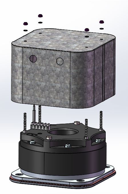
Table of Contents

Table of Contents
1 Preface ................................................................................................. 3
  1.1         Warning Signs and Key Symbols ................................................................... 3
  1.2         More Symbols................................................................................................... 3
  1.3         Laws and Requirements .................................................................................. 4
  1.4         Warranty............................................................................................................ 4
  1.5         Support and Liability ....................................................................................... 4
  1.6         Copyright .......................................................................................................... 4
  Table of Contents ....................................................................................................... 5
  List of Figures............................................................................................................. 7
  List of Tables .............................................................................................................. 8
  Glossary ...................................................................................................................... 9
  Standards for COMBISTOP type 38 Load Brake.................................................... 11
2 Safety Instructions ............................................................................ 12
  2.1         Target Audience ............................................................................................. 12
  2.2         Specified Application ..................................................................................... 13
  2.3         General Safety Guidelines ............................................................................. 13
  2.4         Electrical Safety Guidelines .......................................................................... 13
  2.5         Installation and Operation Safety Guidelines .............................................. 14
  2.6         Maintenance Safety Guidelines .................................................................... 14
  2.7         Personal Protective Equipment .................................................................... 15
3 Product Description .......................................................................... 16
  3.1         Scope of this Manual ..................................................................................... 16
  3.2         Description ..................................................................................................... 16
      3.2.1      Brake Components ............................................................................................................... 16
      3.2.2      Brake Assembly Numbering Scheme ................................................................................. 18
  3.3         Brake Specifications ...................................................................................... 20
4 Installation.......................................................................................... 21
  4.1         Required Tools ............................................................................................... 21
  4.2         Unpacking the Brake ..................................................................................... 22

  ©   2021 KEB America, Inc.                                                                                                                    5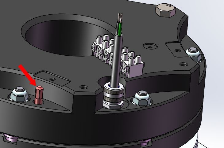
Table of Contents

  4.3         Installing the Brake ........................................................................................ 22
      4.3.1      Mounting the Brake Hub ....................................................................................................... 22
      4.3.2      Removing the Magnet Assembly from the Friction Basket .............................................. 23
      4.3.3      Mounting the Friction Basket Assembly to the Hub.......................................................... 24
      4.3.4      Mounting the Magnet Assembly to the Friction Basket Assembly .................................. 25
      4.3.5      Adjusting the Air Gap ........................................................................................................... 26
      4.3.6      Replacing the Dust Protection Ring and Enclosure .......................................................... 26
  4.4         Testing the Brake Function ........................................................................... 27
5 Optional Components and Accessories .......................................... 28
  5.1         Hand Release Lever ....................................................................................... 28
  5.2         Installation ...................................................................................................... 29
  5.3         Microswitch .................................................................................................... 31
      5.3.1      Installation ............................................................................................................................. 32
  5.4         Enclosure Retrofit .......................................................................................... 34
      5.4.1      Installation ............................................................................................................................. 35

6 Operation............................................................................................ 38
  6.1         Normal Operation ........................................................................................... 38
  6.2         Manual Operation ........................................................................................... 38
7 Rectifiers ............................................................................................ 39
  7.1         Example Wiring Diagrams ............................................................................. 39
      7.1.1      AC Side Switching................................................................................................................. 39
      7.1.2      DC Side Switching................................................................................................................. 41
      7.1.3      OEX Switch Wiring Diagrams .............................................................................................. 43

8 Appendix ............................................................................................ 45
  8.1         Appendix 1: Certification ............................................................................... 45
9 Revision History ................................................................................ 46

  6                                                                                                                 ©   2021 KEB America, Inc.
List of Figures

List of Figures
Figure 1 Brake Parts Diagram .................................................................................................................... 16
Figure 2 Load Brake with optional Hand Release Lever and Microswitch ................................................. 21
Figure 3 Mounting Surface Clearance ........................................................................................................ 22
Figure 4 Hub Mounted to Mounting Surface ............................................................................................... 22
Figure 5 Removing the Enclosure (if present) ............................................................................................ 23
Figure 6 Removing Magnet Assembly from Friction Basket ....................................................................... 23
Figure 7 Spring Washer Orientation ........................................................................................................... 24
Figure 8 Mounting the Friction Basket Assembly........................................................................................ 24
Figure 9 Mounting the Magnet Assembly ................................................................................................... 25
Figure 10 Adjusting the Air Gap .................................................................................................................. 26
Figure 11 Lifting Tab in Storage Position .................................................................................................... 26
Figure 12 Removing the Manual Release Bolts.......................................................................................... 29
Figure 13 Mounting the Hand Release Yoke .............................................................................................. 29
Figure 14 Attaching the Hand Release Handle........................................................................................... 30
Figure 15 Microswitch Assembly ................................................................................................................ 32
Figure 16 Plunger Location ......................................................................................................................... 32
Figure 17 Installing the Microswitch Assembly ........................................................................................... 32
Figure 18 Adjusting the Microswitch Plunger .............................................................................................. 33
Figure 19 Returning the Manual Release Bolts to Normal Operation ........................................................ 33
Figure 20 Enclosure Assembly ................................................................................................................... 35
Figure 21 Gasket Installation ...................................................................................................................... 35
Figure 22 Gasket End ................................................................................................................................. 35
Figure 23 Mounting the Enclosure Studs .................................................................................................... 36
Figure 24 Enclosure Plugs .......................................................................................................................... 36
Figure 25 Enclosure Installation .................................................................................................................. 37
Figure 26 Rectifier Wiring AC Side Switching - Relay Switching - Phase to Neutral.................................. 39
Figure 27 Rectifier Wiring AC Side Switching - Independent Contactor Switching - Phase to Phase ....... 40
Figure 28 Rectifier Wiring AC Side Switching - Motor Contactor Switching - Phase to Phase .................. 40
Figure 29 Rectifier Wiring DC Side Switching - Independent Contactor Switching - Phase to Phase ....... 41
Figure 30 Rectifier Wiring DC Side Switching - Independent Contactor Switching with External MOV -
Phase to Phase ........................................................................................................................................... 42
Figure 31 OEX Wiring AC Side Switching - Independent Contactor Switching - Phase to Phase ............. 43
Figure 32 OEX Wiring DC Side Switching - Independent Contactor Switching - Phase to Phase ............. 44

    ©   2021 KEB America, Inc.                                                                                                                           7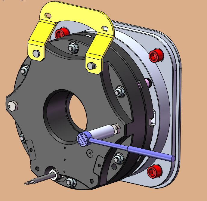
List of Tables

List of Tables
Table 1 Brake Components ........................................................................................................................ 17
Table 2 Part Numbers ................................................................................................................................. 19
Table 3 Coil Specifications .......................................................................................................................... 20
Table 4 Resistance Range .......................................................................................................................... 20
Table 5 Optional Components and Accessories ......................................................................................... 28
Table 6 Hand Release Lever Components ................................................................................................. 28
Table 7 Microswitch Components ............................................................................................................... 31
Table 8 Enclosure Components .................................................................................................................. 34

    8                                                                                                            ©   2021 KEB America, Inc.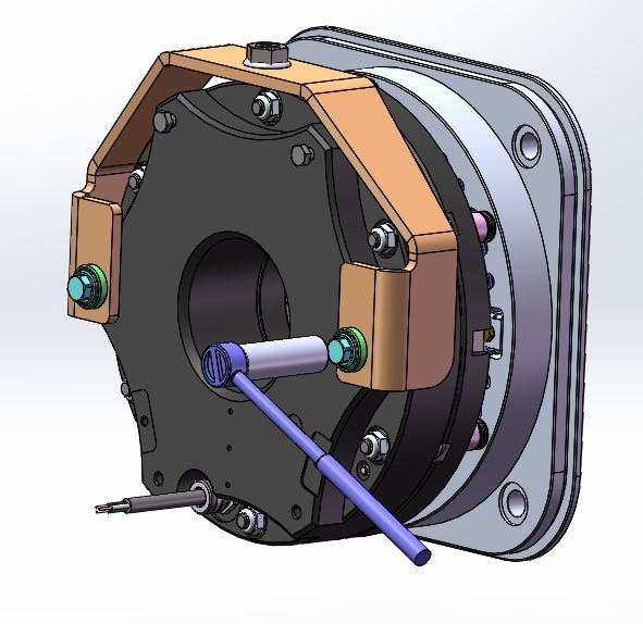
Glossary

Glossary
  AC                           Alternating current.
  Aggressive Fumes/Liquids     Gasses or liquids that are chemically reactive and may cause
                               corrosion in exposed machine parts.
  Air Gap                      The gap between the armature and the magnet. This air gap must
                               be precisely adjusted to a specific width, denoted as X. If the air
                               gap is too wide, the brake may not release torque. If the air gap is
                               too narrow, the brake may drag continuously.
  Application                  The machine/system in which the KEB device is to be used. For
                               brakes the application is typically the motor to which the brake is
                               attached.
  Armature                     The component of the brake connected to the magnet which
                               moves across the air gap to engage or disengage the brake.
                               When powered off the armature is pressed against the friction
                               brake assembly by springs causing braking torque. When
                               powered on the armature is pulled across the air gap by the
                               magnet and the brake releases.
  AWG / Wire Gauge             American Wire Gauge. A measure of the thickness of a wire using
                               standardized sizes.
  Branch Circuit Protection    Circuit protection for the portion of the electrical distribution
                               system that extends beyond the final branch circuit protection
                               device. A branch circuit is used to run motors or other appliances,
                               and is what is commonly found inside a building.
  CE                           European safety standards for products in the European
                               Economic Area. Manufacturers self-test products against these
                               standards to maintain CE certification. The CE mark indicates a
                               product meets EEA safety standards.
  CEC                          Canadian Electric Code. Safety standard for electrical installations
                               used in Canada.
  Control Device/Interface     The COMBISTOP brake is controlled electronically by a control
                               device. This can be as simple as a switch, or as complex as a full
                               suite of control software.
  CSA                          Canadian Standards Authority, also known as CSA Group.
                               Organization that tests and certifies products according to
                               Canadian safety standards. The CSA mark indicates a product
                               meets Canadian safety standards.
  Customer                     The corporation or individual who purchased the COMBISTOP
                               brake.
  DC                           Direct current.
  Device / KEB Device          The COMBISTOP brake described in this manual.
  Drive Shaft                  A mechanical component for transmitting torque and rotation from
                               a motor to other parts of a mechanical system.
  Dry running                  Operation in dry environments with no danger of dripping or
                               splashing liquids.

  ©   2021 KEB America, Inc.                                                                         9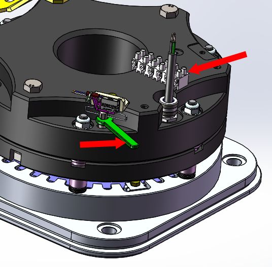
Glossary

  EC Declaration of        Declaration that the device conforms to EU standards of safety.
  Conformity
  Enclosure                A metal covering installed to protect the brake from airborn
                           particles or moisture, and to prevent accidental contact with the
                           brake that may result in injury.
  Equipotential Bonding    A practice of intentionally electrically connecting all exposed metal
                           items not designed to carry electricity in a room as protection from
                           electric shock.
  Flange                   An external flat rim or ridge for attaching an external object to the
                           device.
  KEB Automation KG        Parent company of KEB America, Inc. Also referred to as KEB.
  Machine Manufacturer     The manufacturer of the application in which the COMBISTOP
                           brake is installed. Not KEB America, Inc.
  Magnet                   The component of the brake which contains the magnetic
                           components.
  Mounting Surface         A surface to which the COMBISTOP device is physically
                           attached.
  NEC                      US National Electric Code. Safety standard for electrical
                           installations used in the United States.
  Product / KEB Product    See Device.
  Recommended tightening   The torque required to fully screw a socket head screw into a
  torque                   mounting surface. The recommended tightening torque depends
                           on the type of screw used as well as the material, thread depth
                           and locking components (if any) used in the mounting surface.
                           Refer to the machine manufacturer for details on recommended
                           tightening torques for specific mounting surfaces.
  Run-out                  An inacuracy of rotating mechanical systems whereby the shaft
                           does not rotate precisely in line with the main axis. Always
                           present but must be minimized.
  Specified Application    The specific application for which the COMBISTOP device was
                           ordered, is usually (but not always) the same as the Application in
                           which the device is being used.
  System Integrator        The technician installing the COMBISTOP brake into the
                           application.
  UL                       Independent Standardization Company that tests and certifies
                           products according to defined and industry leading safety
                           standards. The UL mark indicates a product meets UL safety
                           standards.

  10                                                                 ©   2021 KEB America, Inc.
Glossary
Standards for COMBISTOP type 38 Load Brake
The COMBISTOP type 38 Load Brake installation must comply with all relevant safety
standards. The following standards are relevant to the installation and operation of the
Load Brake.
• Directive 2006/42/EC (annex I)
o Region: EU
o Essential health and safety requirements for the design and construction of
machinery.
• C22.1-18: Canadian Electric Code, Part 1 (CEC)
o Region: Canada
o Electric safety code detailing safety standards for electric installations in
Canada.
• NFPA 70: National Electric Code (NEC)
o Region: US
o Electric safety code detailing safety standards for electric installations in the
United States.
• NFPA 79: Electrical Standard for Industrial Machinery
o Region: US
o Industrial safety code detailing safety standards for industrial machinery to
protect against fire and electrical hazards.
• OSHA 1910.137
o Region: US
o Personal safety code detailing appropriate personal protective equipment for
working on electrical installations.
• OSHA 1910.269
o Region: US
o Occupational safety code detailing safety standards for electrical power
generation, transmission, and distribution.
© 2021 KEB America, Inc. 11Safety Instructions
2 Safety Instructions
The COMBISTOP type 38 Load Brake is designed and constructed with state-of-the-art
technology in accordance with recognized safety rules and regulations. Improper use of
this device may cause hazards to life and limb of the user or third-parties, or damage to
the application and other material property.
The following safety instructions have been created by KEB America, Inc. for the Load
Brake. These instructions can be supplemented by local, country- or application-specific
safety instructions where relevant.
Violation of the safety instructions in this manual will result in the loss of any liability
claims.
NOTICE Stay Safe! Stay Informed!
Read the instruction manual prior to operating the device!
Follow all safety and warning instructions!
If you are unsure of any part of these instructions, please contact
KEB prior to operating the device!
2.1 Target Audience
This manual is intended exclusively for the use of qualified electrical/mechanical
technicians. Qualified technicians for the purpose of this document must meet the
following:
• Must have fully read and understood the safety instructions contained in this
manual.
• Must be familiar with the installation and assembly of electrical products.
• Must be familiar with the installation and operation of the product as specified in
this manual.
See the Table 4 Resistance Range
→ Installation and Operation chapters for details.
• Must fully understand the specified application of the product.
→ See the Specified Application section for details.
• Must be familiar with the hazards and risks of mechanical braking technology.
• Must be familiar with appropriate electrical and safety codes:
o US: NFPA 70 National Electric Code (NEC)
o Canada: Canadian Electric Code, C22 Part 1 (CEC)
• Must be familiar with national safety regulations (e.g. OSHA Title 29 CFR):
→ See the Standards for COMBISTOP type 38 Load Brake section for details.
12 © 2021 KEB America, Inc.Safety Instructions
2.2 Specified Application
The operational reliability of the brake is only guaranteed when the device is used for the
specified application. In this context, specified application means the purpose for which
the brake was ordered and configured.
Any use of the brake outside of this specified application is considered at the user’s own
risk. Such unintended uses may pose unforeseeable risks or hazards. KEB America, Inc.
retains no liability for any damage or injury resulting from the use of a COMBISTOP
brake outside of the specified application.
2.3 General Safety Guidelines
Carefully observe the following safety guidelines before installation or operation of the
device.
• Only trained personnel should operate the brake.
• Immediately remove the brake from operation in case of a malfunction.
• Malfunctions should be corrected by trained personnel before returning the brake
to operation.
• Never use the brake in potentially explosive environments.
• The brake may not be modified or altered in any way not intended by KEB
America, Inc.
2.4 Electrical Safety Guidelines
DANGER Rick of electrical shock!
Turn off the power supply and secure it against switching on prior
to any work on the device.
Never bridge branch circuit protection devices.
Carefully observe the following safety guidelines during the electrical installation.
• Observe all relevant safety standards for the device.
→ See the Standards for COMBISTOP type 38 Load Brake section for
details specific to the product.
• Use only wire gauges and fuses rated for the power requirements of the device.
• Ensure new or existing circuits meet NEC or applicable local requirements.
• The device must be appropriately grounded by a connector from the magnet and
the fixed installation.
• When using components without isolated inputs/outputs, equipotential bonding
must be used between the connected components to prevent damage to the
device.
• Do not exceed specified electrical voltage and currant limits.
© 2021 KEB America, Inc. 13Safety Instructions
2.5 Installation and Operation Safety Guidelines
WARNING Moving parts can crush and cut!
Contact with rotating or moving parts may cause serious injury.
Ensure adequate protection around the brake to prevent
accidental contact!
CAUTION Hot Surfaces!
The heat generated during the operation of the brake may cause
burns on contact with skin. Always wear appropriate protective
equipment!
Do not start the device until you have confirmed that the installation complies with the
following safety standards.
• Ensure there is sufficient protection against foreign particles entering the air gap.
These particles may impede the motion of the armature.
• Ensure there is sufficient thermal protection such that the brake or clutch does
not exceed or fall below the listed temperature limits for the device.
• Ensure there is protection against accidental contact with rotating or moving
parts.
• Ensure there is sufficient protection from environmental factors such as moisture
or aggressive gases that may compromise the integrity of the friction surface or
armature.
2.6 Maintenance Safety Guidelines
DANGER Risk of electrical shock!
Turn off the power supply and secure it against switching on prior
to any maintenance on the brake.
WARNING Moving parts can crush and cut!
Contact with rotation or moving parts may cause serious injury.
Wait until the drive has come to a complete stop before
performing any maintenance.
Secure the drive against accidental movement prior to
performing any maintenance.
CAUTION Hot Surfaces!
The heat generated during the operation of the brake may cause
burns on contact with skin. Always wear appropriate protective
equipment.
Carefully observe the following safety guidelines before performing maintenance on the
brake.
14 © 2021 KEB America, Inc.Safety Instructions
• Ensure the device is powered off and has come to a complete stop before
performing any maintenance.
• Secure the brake so it cannot be switched on accidentally during maintenance.
• Disconnect the brake from the load before maintenance to avoid uncontrolled
movements.
• Ensure there is sufficient protection against foreign particles entering the air gap
during maintenance.
• Ensure there is sufficient protection against moisture or aggressive gasses that
may compromise the integrity of the friction surface or armature.
2.7 Personal Protective Equipment
When installing or performing maintenance on the brake or clutch, use the following
personal protective equipment:
• Long-sleeved protective clothing
• Safety gloves
• Safety shoes
• Safety goggles
The personal protective equipment must be provided by the operating company and must
comply with any applicable safety regulations.
© 2021 KEB America, Inc. 15Product Description
3 Product Description
3.1 Scope of this Manual
This manual describes the installation and operation of the KEB size 10 COMBISTOP
Type 38 Load Brake. The Load Brake is a specialized version of the COMBISTOP spring
set brake designed for quiet running and loads optimized for the theater industry.
The size 10 Load Brake can be mounted to an adaptor flange on the gearbox, or directly
on the bulkhead of the machine.
This manual also covers the installation of a microswitch and hand release lever for the
brake, as well as explaining the different rectifiers available for the Load Brake.
3.2 Description
3.2.1 Brake Components
Figure 1 Brake Parts Diagram
Brake Components
Component Name Number Included
1 Brake basket assembly 1
2 Magnet assembly 1
16 © 2021 KEB America, Inc.Product Description
Brake Components
Component Name Number Included
3 Hub 1
4 M10 spring washers 30 (5 per stud)
5 M10 nylon lock-nuts 6 (1 per stud)
6 M10 washers 6 (1 per stud)
7 Hand release lever (optional) 1
8 Microswitch (optional) 1
9 Customer supplied mounting bolts (M16 or 5/8‘‘) 4
10 Rubber dust ring 1
11 Hand release spherical washers (optional) 2
12 Hand release bolts (optional) 2
13 Metal enclosure (optional, cannot be used with hand 1
release lever)
14 Sealing Washer (optional) 4
15 Stud for enclosure mount (optional) 4
16 M8 nylon lock-nut for enclosure (optional) 4
17 Lifting eyebolt for hand release lever (optional) 1
18 Lifting tab for standard bolt release 1
Table 1 Brake Components
© 2021 KEB America, Inc. 17Product Description
3.2.2 Brake Assembly Numbering Scheme
The part number for a COMBISTOP brake describes the device type as well as options
specified for the device. It is important to order the correct brake for your specified
application. Consult the following table for a description of Load Brake part numbers and
their meanings.
XX TY P A B C D E F
F: Special Designation
E: Options
D: Hub Bore
C: Coil Voltage
B: Torque Rating
A: Flange
P: Disk Code (fixed)
TY: Type Code (fixed)
XX: Brake Size
Part Number Component Descriptions
Number Name Options Description
XX Brake Size 10 The only size described in this manual (Fixed)
TY Type Code 38 Spring Set Brake (Fixed)
P Disc Code M Multi-Disk Brake (Fixed)
A Flange Type 0 Generic Flange
1 Generic Flange with Enclosure (Bolt release only)
B Torque Rating 3 1600 Nm
4 2133 Nm
5 2667 Nm
6 3200 Nm
C Coil Voltage 0 24 VDC, 6.25 Amps
1 105 VDC, 1.44 Amps
2 170 VDC, 0.88 Amps
3 205 VDC, 0.74 Amps
4 270 VDC, 0.56 Amps
D Hub Bore (Metric) 0 44 mm, T max: 1600 Nm
1 50 mm, T max: 1600 Nm
18 © 2021 KEB America, Inc.Product Description
Part Number Component Descriptions
Number Name Options Description
2 55 mm, T max: 2133 Nm
3 60 mm, T max: 2133 Nm
4 65 mm, T max: 2667 Nm
5 70 mm, T max: 3200 Nm
6 75 mm, T max: 3200 Nm
7 80 mm, T max: 3200 Nm
8 85 mm, T max: 3200 Nm
9 90 mm, T max: 3200 Nm
Hub Bore B 1.875‘‘, T max: 2133 Nm
(Inches)
C 2.000‘‘, T max: 2133 Nm
D 2.125‘‘, T max: 2667 Nm
E 2.250‘‘, T max: 2667 Nm
F 2.375‘‘, T max: 3200 Nm
G 2.500‘‘, T max: 3200 Nm
H 2.625‘‘, T max: 3200 Nm
I 2.750‘‘, T max: 3200 Nm
J 2.875‘‘, T max: 3200 Nm
K 3.000 ‘‘, T max: 3200 Nm
L 3.125 ‘‘, T max: 3200 Nm
M 3.250 ‘‘, T max: 3200 Nm
E Options 0 Bolt release, no microswitch
1 Hand release, no microswitch
2 Bolt release with microswitch
3 Hand release with microswitch
4 Bolt release with double microswitches
5 Hand release with double microswitches
F Special 0 Standard
Designation
X Special, number C, D and E are randomized
Table 2 Part Numbers
© 2021 KEB America, Inc. 19Product Description
3.3 Brake Specifications
Coil Specifications
Specification Value
Voltage Variable
Power 150W
Current 150W / Coil Voltage
Mounting Can be mounted vertically or horizontally
Max Operating Speed 200 RPM
Table 3 Coil Specifications
Resistance Range
Coil Voltage Resistance (Ω)
24 VDC 3.6 – 4.1
105 VDC 68.3 – 78.5
170 VDC 179 – 206
205 VDC 260 – 300
270 VDC 452 – 520
Table 4 Resistance Range
20 © 2021 KEB America, Inc.Installation
4 Installation
NOTICE Stay Safe! Stay Informed!
Read and follow all safety instructions prior to installing the Load
Brake.
The following sections detail the steps for unpacking and installing the size 10
COMBISTOP type 38 Load Brake (shown below). Read this chapter thoroughly before
beginning the installation process.
Figure 2 Load Brake with optional Hand Release Lever and Microswitch
4.1 Required Tools
You will need the following tools before you begin the Load Brake installation.
• Customer supplied hex key for Brake basket mounting bolts
• 17mm wrench and/or socket for Magnet assembly nuts
• 19mm wrench and/or socket for standard release bolts
• 15mm wrench and/or socket for hand release bolts
• 13mm wrench for enclosure stud mounting nuts and lifting tab bolts
• 10mm wrench and or socket for micro-switch mounting bolt.
• 8mm open end wrench for micro-switch adjustment
• Feeler gage set
• Digital multimeter for micro-switch setup
© 2021 KEB America, Inc. 21Installation
4.2 Unpacking the Brake
CAUTION Heavy Objects!
Large sizes of the Load Brake can be too heavy to safely lift by
hand. Use appropriate lifting equipment to transport the size 10
Load Brake.
1. Remove the packaging from the brake.
2. Inspect the complete brake assembly for damage or defect.
i Report any shipping damage to the device or packing to the
shipping company and to KEB America, Inc.
3. Remove the rubber dust ring, if installed.
4. Remove cardboard packaging strips holding the hub in place.
4.3 Installing the Brake
Installation of the Size 10 Load Brake consists of six steps, each of which is described in
more detail in the following sections.
1. Mounting the brake hub to the machine frame.
2. Remove the magnet assembly from the friction basket assembly.
3. Mount the friction basket assembly to the hub.
4. Mount the magnet assembly to the friction basket assembly.
5. Adjust the air gap.
6. Replace the dust protection ring and enclosure (if used)
4.3.1 Mounting the Brake Hub
Figure 3 Mounting Surface Clearance Figure 4 Hub Mounted to Mounting Surface
1. Set the brake hub onto the shaft positioned 1 – 2 mm from the mounting surface.
Orient the hub with the splines facing away from the mounting surface.
22 © 2021 KEB America, Inc.Installation
2. Locate the hub with retaining rings, shaft shoulders, spacer sleeves, clamp washers or a
clamp collar.
• The maximum diameter inside the brake is 100mm. A clamp-collar O.D. must be
smaller than 100mm.
• A retaining ring may have any O.D.
3. Using a feeler gauge, ensure the runout on the hub O.D. and hub face is less than 0.25
mm.
4. Ensure the hub is centered in the brake mounting pattern to less than 0.5 mm when
measured from the four mounting holes.
4.3.2 Removing the Magnet Assembly from the Friction Basket
Figure 5 Removing the Enclosure (if present) Figure 6 Removing Magnet Assembly from Friction Basket
1. If the brake has the optional enclosure, remove the four M8 nylon lock nuts (13mm hex)
and the four sealing washers, then lift the enclosure off the studs and set it aside.
2. Remove the rubber dust ring from the magnet.
3. Using a 17mm wrench/socket, remove the six M10 lock nuts from the studs that hold the
magnet to the friction basket.
i Do not turn or remove the two black manual release bolts (19mm
hex) or the two hand release lever bolts (15mm hex, hand release
option) as they hold the magnet assembly together.
4. Lift the magnet off the studs and set it aside.
i Do not disassemble the friction basket assembly.
© 2021 KEB America, Inc. 23Installation
5. Note the orientation of the five spring washer stacks on each stud. An O-ring is installed
to keep the washers from falling off. If the washers do fall off during this process, the first
washer is installed with the I.D. cone facing up. The next four washers alternate I.D. cone
facings as shown below.
Figure 7 Spring Washer Orientation
4.3.3 Mounting the Friction Basket Assembly to the Hub
Figure 8 Mounting the Friction Basket Assembly
1. Lift the friction basket assembly by holding two of the six studs.
2. Slide the friction basket assembly over the hub.
• If the teeth do not engage easily, apply thumb pressure on the blue friction plate
while rotating the basket clockwise and counterclockwise 45°.
• The rotation should cause the teeth to engage the hub disk by disk until the whole
basket comes in contact with the machine frame.
3. Align the mounting holes and using the customer supplied bolts and lock washers, fasten
the friction basket assembly to the machine frame as shown above.
24 © 2021 KEB America, Inc.Installation
4.3.4 Mounting the Magnet Assembly to the Friction Basket Assembly
Figure 9 Mounting the Magnet Assembly
1. Orient the magnet as desired with the lifting tab at the top or bottom.
2. Slide the magnet assembly onto the six studs of the friction brake assembly until the
magnet contacts the friction brake.
3. Place the flat washers onto the studs and start each of the six lock nuts.
4. Using a 17mm wrench, tighten the lock nuts equally in stages, reducing the air gap of the
magnet to approximately 2mm.
• The air gap will be adjusted more precisely in the next section.
i It may be easier to tighten the nuts three at a time to ensure the
magnet remains flat in relation to the friction brake assembly.
© 2021 KEB America, Inc. 25Installation
4.3.5 Adjusting the Air Gap
Figure 10 Adjusting the Air Gap
1. The air gap should be between 1.5 and 1.7mm. Place a feeler gauge between the
armature and magnet as shown above.
2. Tighten/loosen the nuts equally until the air gap measures between 1.5 and 1.7mm.
3. Using the feeler gauge, check the air gap around the entire circumference of the magnet
to ensure proper operation.
4.3.6 Replacing the Dust Protection Ring and Enclosure
Figure 11 Lifting Tab in Storage Position
1. When the air gap is set correctly, remove the lifting tab from the magnet assembly and
set aside, if using the optional enclosure, or replace in storage position as shown above.
26 © 2021 KEB America, Inc.Installation
2. Replace the dust protection ring over the brake spanning the gap between magnet
assembly and flange.
• Ensure the lead wire does not get trapped by the dust protection ring.
3. If using the optional enclosure, replace the enclosure onto the magnet studs.
4. Place the sealing washers on the magnet studs, and then fasten the four M8 nylon lock
nuts to securely attach the enclosure to the Load Brake.
4.4 Testing the Brake Function
After installing the Load Brake, it is recommended to test the brake function to sure the
installation was performed successfully.
1. Power on the brake with nominal voltage and verify the armature disengages.
2. Check for free rotation of the shaft while the brake is powered on.
3. Power off the brake and verify the armature engages.
4. Check for free rotation of the shaft while the brake is powered off. The shaft should not
rotate with the brake engaged.
WARNING After performing an emergency stop inspect the brake components
and test the brake performance before continued use.
© 2021 KEB America, Inc. 27Optional Components and Accessories
5 Optional Components and Accessories
The Size 10 COMBISTOP Load Brake has several optional components and accessories
that can be ordered with the brake or separately as an upgrade kit. The following sections
contain instructions on installing these optional components.
Optional Components and Accessories
Component Part Number
Hand Release Lever 1038520-M01U
Microswitch 1038270-M01U
Enclosure Retrofit 1038560-M02U
Table 5 Optional Components and Accessories
5.1 Hand Release Lever
Part Number: 1038520-M01U
Kit Components
Component Number Included
Handle 1
Yoke 1
Bolt 2
Washer 2
Table 6 Hand Release Lever Components
The optional Hand Release Lever provides a manual backup to the standard electronic
brake release for releasing the brake in power failure situations.
To use the Hand Release Lever, pull directly away from the mounting surface with at
least 70lbs of force.
The handle of the Hand Release Lever can optionally be replaced by a lifting eyebolt as
needed for the specific application.
The Hand Release Lever is incompatible with the optional brake enclosure. If the Load
Brake has an enclosure, it must be removed prior to installing the Hand Release Lever.
28 © 2021 KEB America, Inc.Optional Components and Accessories
5.2 Installation
Figure 12 Removing the Manual Release Bolts
1. Using a 19mm wrench/socket, remove the two manual release bolts from the magnet
assembly as shown above.
2. Remove the lifting tab or move it to storage position if the lifting tap is still in the
installation position.
• The lifting tab will interfere with the operation of the Hand Release Lever if left in
installation position.
3. Mount the hand release yoke to the magnet using the included bolts and washers as
shown below.
Figure 13 Mounting the Hand Release Yoke
4. Tighten the bolts to 80Nm with a 15mm wrench/socket.
5. Screw the hand release handle to the yoke, ensuring a tight fit.
© 2021 KEB America, Inc. 29Optional Components and Accessories
Figure 14 Attaching the Hand Release Handle
6. Test the Hand Release Lever before returning the brake to operation.
i A pull force of 70lbs is required to release the Load Brake via the
hand release lever.
30 © 2021 KEB America, Inc.Optional Components and Accessories
5.3 Microswitch
Part Number: 1038270-M01U
Kit Components
Component Number Included
Microswitch 1
Screw M2x10 2
Screw M2x4 1
Heat Sink 1
Bracket 1
Screw M6x16 1
Detent Wire 1
Locking Washer S6 1
Plunger 1
Microswitch Lever 1
Cable Tie 1
Table 7 Microswitch Components
Up to two Microswitches can be installed to detect whether the brake is engaged or
disengaged.
Typically a single Microswitch is used to detect when the powered-on brake disengages.
This can be used to signal the system that the shaft is free to rotate, or that the motor is
free to engage. This Microswitch is typically installed to the left of the lead wire on the
magnet assembly.
A second Microswitch can be used to detect when the powered-off brake engages, or it
can be used as a wear indicator. A second Microswitch is typically installed to the right of
the lead wire on the magnet assembly.
• If used to detect whether the brake is engaged, the Microswitch can be
configured to trip at less than the air gap distance (approximately 0.9mm) to
signal the system that the brake is applying braking torque. Certain specific
applications may require Microswitches to detect both the brake disengaged and
brake engaged states leading to this use of two Microswitches.
• If used as a wear indicator, the Microswitch is configured to trip when the
armature moves further than the recommended air gap setting of 1.7mm.
Typically a wear indicator Microswitch is set to trip at 1.9mm, letting the operator
know that the friction surface may need to be replaced or the air gap adjusted.
© 2021 KEB America, Inc. 31Optional Components and Accessories
5.3.1 Installation
Figure 15 Microswitch Assembly Figure 16 Plunger Location
1. Install the plunger on the M6 stud as show above.
• The microswitch is typically mounted on the lead wire side of the magnet.
2. Screw the plunger down until it is 5mm below the back of the magnet.
3. Slide the Microswitch assembly into place with the anti-rotation wire behind the plunger
as shown below.
Figure 17 Installing the Microswitch Assembly
4. Fasten the assembly with a single M6 hex head bolt using a 10mm wrench/socket.
5. Connect the Microswitch leads to a digital multimeter and set the meter to diode test
settings. The meter should read OL indicating an open switch connection.
• Microswitch black to blue = normally open.
• Microswitch black to grey = normally closed for reverse logic use.
6. Attach the lead wire to a power supply with the correct voltage for the brake and turn the
power on. This will pull the armature flush with the magnet.
• Alternately: Tighten the two manual release bolts until the armature is pulled flush
with the magnet to simulate active power.
7. Adjust the plunger out using an 8mm open end wrench until the plunger contacts the
Microswitch lever as shown below.
• The terminal strip on the Load Brake can be used for Microswitch connections.
32 © 2021 KEB America, Inc.Optional Components and Accessories
Figure 18 Adjusting the Microswitch Plunger
8. Continue to unscrew the plunger until the switch trips and the multimeter begins to beep.
Adjust the plunger 1/6 turn further. The Microswitch is now set.
9. Remove power to the Load Brake and verify the Microswitch releases.
• If you used the manual release bolts to simulate active power, unfasten the bolts to
their previous position before returning the brake to active use.
• Loosen the release bolts until the square nut is flush with the armature as shown
below.
Figure 19 Returning the Manual Release Bolts to Normal Operation
10. Test the Microswitch functionality by power cycling the brake several times to ensure the
Microswitch engages every time the brake is powered on.
© 2021 KEB America, Inc. 33Optional Components and Accessories
5.4 Enclosure Retrofit
Part Number: 1038560-M02U
Kit Components
Component Number Included
Enclosure 1
Gasket 1
Stud M8x80 4
Nut M8 Standard 4
Seal Washer M8 4
Nut M8 Nylon 4
Plug 1.093 4
Table 8 Enclosure Components
The enclosure provides protection for the Load Brake from external particles and
moisture, as well as providing protection from accidental contact with the brake while in
operation, which may result in injury.
The enclosure is incompatible with the manual Hand Release Lever. Only one of these
options can be attached to a single Load Brake.
34 © 2021 KEB America, Inc.Optional Components and Accessories
5.4.1 Installation
Figure 20 Enclosure Assembly
1. Peel the backing from the gasket and insert into the grove on the Load Brake flange.
2. Overlap the finished end of the gasket over the beginning and cut through both with a
knife at a diagonal angle.
3. Remove the loose ends and press the gasket ends together while pressing down, as
shown below.
Figure 21 Gasket Installation Figure 22 Gasket End
4. Screw the M8 standard nuts 12mm onto the M8x80 enclosure studs.
5. Screw the studs into the back of the magnet about 10mm deep.
6. Tighten the nuts against the magnet as shown below.
© 2021 KEB America, Inc. 35Optional Components and Accessories
Figure 23 Mounting the Enclosure Studs
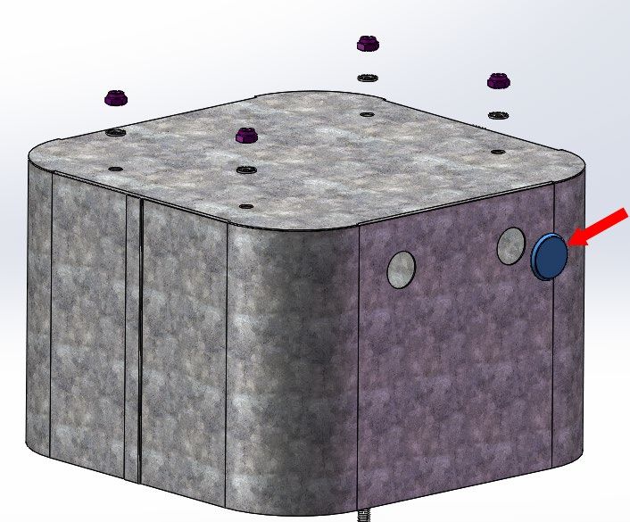
7. Insert the plugs into the holes on the enclosure that will not be used for wire ingress.
• Four holes are provided for ¾’’ connection fittings.
Figure 24 Enclosure Plugs
8. Install the customer supplied glands into the enclosure holes that will be used for wire
ingress.
9. Run wires through the glands for power and Microswitch (if installed).
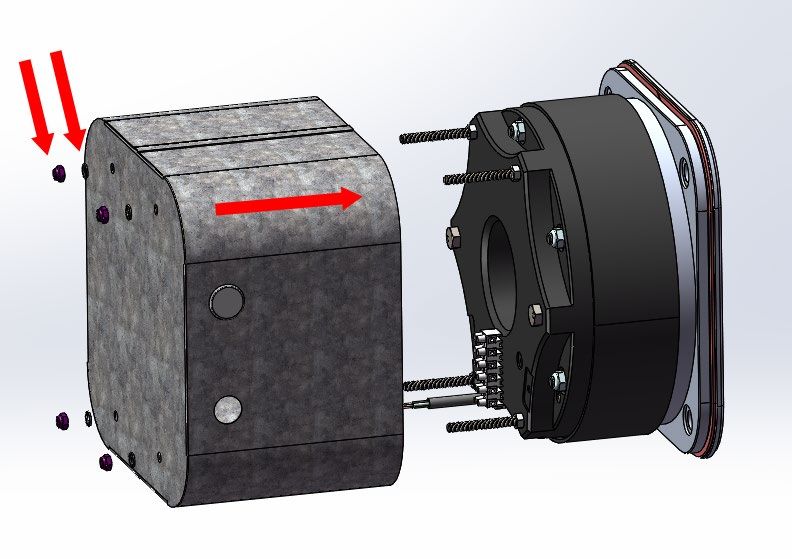
10. Place the enclosure onto the magnet studs as shown below.
36 © 2021 KEB America, Inc.Optional Components and Accessories
Figure 25 Enclosure Installation
11. Place the sealing washers onto the studs, then loosely fasten the M8 nylon nuts.
12. Tighten the nuts equally until the back metal of the enclosure begins to deflect inwards.
i Do not over-tighten the nuts or damage to the enclosure may occur.
© 2021 KEB America, Inc. 37Operation
6 Operation
6.1 Normal Operation
The COMBISTOP type 38 Load Brake is an electrically activated spring set brake. The
brake is normally engaged with power off preventing rotation of the shaft.
When a nominal voltage is applied to the brake, the electromagnet disengages the brake
allowing free rotation of the shaft.
Operation of the brake is typically performed automatically through a customer supplied
control system. There is no manual operation of the Load Brake unless the optional Hand
Release Lever is installed.
6.2 Manual Operation
With the optional Hand Release Lever, the brake may be disengaged manually by pulling
the lever directly away from the mounting surface to which the brake is attached. When
the lever is released, the brake engages once more preventing rotation of the shaft.
The Hand Release Lever is intended for emergency release of the brake in power failure
situations, and should not be used as the standard method of operation of the Load
Brake.
38 © 2021 KEB America, Inc.Rectifiers
7 Rectifiers
Several rectifiers are available for the COMBISTOP Load Brake. Size 04 KEB rectifiers
can be used on the AC side or for simultaneous AC and DC side switching. An over-
excitation or OEX switch is also available for simultaneous AC and DC side switching.
Simultaneous AC and DC side switching guarantees short disconnecting times and
reduces contact erosion. For simultaneous switching it is recommended to also use a
MOV on the DC side.
AC side switching will yield slower switching times but requires no protective measures
for the coil and switching contacts.
7.1 Example Wiring Diagrams
7.1.1 AC Side Switching
AC Side – Relay Switching – Phase to Neutral
Switching: AC Side Rectifier: Full-wave Model Number: 0291020-CE07
Line Voltage: 120VAC Input Voltage: 120VAC Coil Voltage: 105VDC
Fbrk = Class CC fuse max. 5A Relay Contact: 120VAC 5A
Figure 26 Rectifier Wiring AC Side Switching - Relay Switching - Phase to Neutral
© 2021 KEB America, Inc. 39Rectifiers
AC Side – Independent Contactor Switching – Phase to Phase
Switching: AC Side Rectifier: Full-wave Model Number: 0491020-CE07
Line Voltage: 208VAC Input Voltage: 208VAC Coil Voltage: 170VDC
Line Voltage: 230VAC Input Voltage: 230VAC Coil Voltage: 205VDC
Fbrk = Class CC fuse max. 5A Independent Contactor rated 300VAC, min 5A AC1
Figure 27 Rectifier Wiring AC Side Switching - Independent Contactor Switching - Phase to Phase
AC Side – Motor Contactor Switching – Phase to Phase
Figure 4.2.5
Switching: AC Side Rectifier: Half-wave Model Number: 0691020-CE07
Line Voltage: 400VAC Input Voltage: 400VAC Coil Voltage: 170VDC
Line Voltage: 480VAC Input Voltage: 480VAC Coil Voltage: 205VDC
Fbrk = Class CC fuse max. 5A Motor Contactor sized for motor, min 5A
Figure 28 Rectifier Wiring AC Side Switching - Motor Contactor Switching - Phase to Phase
40 © 2021 KEB America, Inc.Rectifiers
7.1.2 DC Side Switching
DC Side – Independent Contactor Switching – Phase to Phase
Switching: DC Side Rectifier: Half-wave Model Number: 0491010-CE07
Line Voltage: 208VAC Input Voltage: 208VAC Coil Voltage: 95VDC
Line Voltage: 230VAC Input Voltage: 230VAC Coil Voltage: 105VDC
Rectifier: Full-wave Model Number: 0491020-CE07
Line Voltage: 208VAC Input Voltage: 208VAC Coil Voltage: 170VDC
Line Voltage: 230VAC Input Voltage: 230VAC Coil Voltage: 205VDC
Fbrk = Class CC fuse max. 5A Kbrk_dc = min 300VDC 9A AC3
Optional redundant contactor for safety Kbrk_ac = min 300VAC 5A AC1
Figure 29 Rectifier Wiring DC Side Switching - Independent Contactor Switching - Phase to Phase
© 2021 KEB America, Inc. 41Rectifiers
DC Side – Independent Contactor Switching with external MOV – Phase to Phase
Switching: DC Side Rectifier: Half-wave Model Number: 0691010-001U
Line Voltage: 400VAC Input Voltage: 400VAC Coil Voltage: 170VDC
Line Voltage: 480VAC Input Voltage: 480VAC Coil Voltage: 205VDC
Fbrk = Class CC fuse max. 5A Kbrk_dc = min 600VDC 9A MOV: 625Vrms / 1000Vpk / 500J
AC3 Installed at the brake
Optional redundant contactor for safety Kbrk_ac = min 600VAC 5A AC1
Figure 30 Rectifier Wiring DC Side Switching - Independent Contactor Switching with External
MOV - Phase to Phase
42 © 2021 KEB America, Inc.Rectifiers
7.1.3 OEX Switch Wiring Diagrams
The OEX Rectifier excites the brake magnet with the nominal voltage and then reduces
the voltage by 50% for holding. This reduced holding voltage significantly reduces the
power consumption and speeds up the engagement of the brake when the voltage is
switched off.
AC Side – Independent Contactor Switching – Phase to Phase
Figure 4.2.4
Switching: AC Side Rectifier: OEX Switch Model Number: 9098200-CE09
Line Voltage: 208VAC Input Voltage: 208VAC Coil Voltage: 170VDC
Line Voltage: 230VAC Input Voltage: 230VAC Coil Voltage: 205VDC
Fbrk = Class CC fuse max. 5A Independent Contactor rated 300VAC, min 5A AC1
Figure 31 OEX Wiring AC Side Switching - Independent Contactor Switching - Phase to Phase
© 2021 KEB America, Inc. 43Rectifiers
DC Side – Independent Contactor Switching – Phase to Phase
Figure 4.2.6
Switching DC Side Rectifier: OEX Switch Model Number: 9098200-CE09
Line Voltage: 208VAC Input Voltage: 208VAC Coil Voltage: 170VDC
Line Voltage: 230VAC Input Voltage: 230VAC Coil Voltage: 205VDC
Fbrk = Class CC fuse max. 5A Kbrk_dc = min 300VDC 9A AC3
Optional redundant contactor for safety Kbrk_ac = min 300VAC 5A AC1
Figure 32 OEX Wiring DC Side Switching - Independent Contactor Switching - Phase to Phase
44 © 2021 KEB America, Inc.Appendix 8 Appendix 8.1 Appendix 1: Certification © 2021 KEB America, Inc. 45
Revision History

9 Revision History
 Chapter                  Change                                                               Date

 Instruction Manual       Initial Publication                                                  09/2020

 3.2.2, 3.3, 4.3.5, 5.3   Updated current specifications, microswitch and air gap distances    07/2021

  46                                                                         ©   2021 KEB America, Inc.
Revision History

  ©   2021 KEB America, Inc.   47
Austria | KEB Antriebstechnik Austria GmbH             Japan | KEB Japan Ltd.
Ritzstraße 8 4614 Marchtrenk Austria                   15 - 16, 2 - Chome, Takanawa Minato-ku
Tel: +43 7243 53586-0 Fax: +43 7243 53586-21           Tokyo 108 - 0074 Japan
E-Mail: info@keb.at Internet: www.keb.at               Tel: +81 33 445-8515 Fax: +81 33 445-8215
                                                       E-Mail: info@keb.jp Internet: www.keb.jp
Belgium | KEB America, Inc.
Herenveld 2 9500 Geraardsbergen Belgium                P.R. China | KEB Power Transmission Technology (Shanghai)
Tel: +32 544 37860 Fax: +32 544 37898                  Co. Ltd. No. 435 QianPu Road Chedun Town Songjiang District
E-Mail: vb.belgien@keb.de Internet: www.keb.de         201611 Shanghai P.R. China
                                                       Tel: +86 21 37746688 Fax: +86 21 37746600
Brazil | KEB SOUTH AMERICA - Regional Manager          E-Mail: info@keb.cn Internet: www.keb.cn
Rua Dr. Omar Pacheco Souza Riberio, 70
CEP 13569-430 Portal do Sol, São Carlos Brazil         Republic of Korea | KEB America, Inc.
Tel: +55 16 31161294 E-Mail: roberto.arias@keb.de      Room 1709, 415 Missy 2000 725 Su Seo Dong
                                                       Gangnam Gu 135- 757 Seoul Republic Korea
France | Société Française KEB SASU                    Tel: +82 2 6253 6771 Fax: +82 2 6253 6770
Z.I. de la Croix St. Nicolas 14, rue Gustave Eiffel    E-Mail: vb.korea@keb.de
94510 La Queue en Brie France
Tel: +33 149620101 Fax: +33 145767495                  Russian Federation | KEB RUS Ltd.
E-Mail: info@keb.fr Internet: www.keb.fr               Lesnaya str, house 30 Dzerzhinsky MO
                                                       140091 Moscow region Russian Federation
Germany | Headquarters                                 Tel: +7 495 6320217 Fax: +7 495 6320217
KEB Automation KG                                      E-Mail: info@keb.ru Internet: www.keb.ru
Südstraße 38 32683 Barntrup Germany
Telefon +49 5263 401-0 Telefax +49 5263 401-116        Spain | KEB America, Inc.
E-Mail: info@keb.de Internet: www.keb.de               c / Mitjer, Nave 8 - Pol. Ind. LA MASIA
                                                       08798 Sant Cugat Sesgarrigues (Barcelona) Spain
Germany | Geared Motors                                Tel: +34 93 8970268 Fax: +34 93 8992035
KEB Antriebstechnik GmbH                               E-Mail: vb.espana@keb.de
Wildbacher Straße 5 08289 Schneeberg Germany
Telefon +49 3772 67-0 Telefax +49 3772 67-281          United Kingdom | KEB (UK) Ltd.
Internet: www.keb-drive.de E-Mail: info@keb-drive.de   5 Morris Close Park Farm Indusrial Estate
                                                       Wellingborough, Northants, NN8 6 XF United Kingdom
Italia | KEB Italia S.r.l. Unipersonale                Tel: +44 1933 402220 Fax: +44 1933 400724
Via Newton, 2 20019 Settimo Milanese (Milano) Italia   E-Mail: info@keb.co.uk Internet: www.keb.co.uk
Tel: +39 02 3353531 Fax: +39 02 33500790
E-Mail: info@keb.it Internet: www.keb.it               United States | KEB America, Inc
                                                       5100 Valley Industrial Blvd. South
                                                       Shakopee, MN 55379 United States
                                                       Tel: +1 952 2241400 Fax: +1 952 2241499
                                                       E-Mail: info@kebamerica.com Internet: www.kebamerica.com
Automation with Drive www.kebamerica.com KEB America, Inc. 5100 Valley Industrial Blvd S Shakopee, MN 55379 Tel. +1 952-224-1400 E-Mail: info@kebamerica.com
You can also read