Design of a Reconfigurable Wall Disinfection Robot - MDPI
←
→
Page content transcription
If your browser does not render page correctly, please read the page content below
sensors
Article
Design of a Reconfigurable Wall Disinfection Robot
Ash Wan Yaw Sang , Chee Gen Moo                         , S. M. Bhagya P. Samarakoon          , M. A. Viraj J. Muthugala *
and Mohan Rajesh Elara

                                          Engineering Product Development Pillar, Singapore University of Technology and Design, 8 Somapah Rd,
                                          Singapore 487372, Singapore; ash_wan@mymail.sutd.edu.sg (A.W.Y.S.); cheegen_moo@sutd.edu.sg (C.G.M.);
                                          bhagya_samarakoon@mymail.sutd.edu.sg (S.M.B.P.S.); rajeshelara@sutd.edu.sg (M.R.E.)
                                          * Correspondence: viraj_jagathpriya@sutd.edu.sg

                                          Abstract: During a viral outbreak, such as COVID-19, autonomously operated robots are in high
                                          demand. Robots effectively improve the environmental concerns of contaminated surfaces in public
                                          spaces, such as airports, public transport areas and hospitals, that are considered high-risk areas.
                                          Indoor spaces walls made up most of the indoor areas in these public spaces and can be easily
                                          contaminated. Wall cleaning and disinfection processes are therefore critical for managing and
                                          mitigating the spread of viruses. Consequently, wall cleaning robots are preferred to address the
                                          demands. A wall cleaning robot needs to maintain a close and consistent distance away from a
                                          given wall during cleaning and disinfection processes. In this paper, a reconfigurable wall cleaning
                                          robot with autonomous wall following ability is proposed. The robot platform, Wasp, possess inter-
                                          reconfigurability, which enables it to be physically reconfigured into a wall-cleaning robot. The wall
                                          following ability has been implemented using a Fuzzy Logic System (FLS). The design of the robot
                                          and the FLS are presented in the paper. The platform and the FLS are tested and validated in several
                                          test cases. The experimental outcomes validate the real-world applicability of the proposed wall

                                   following method for a wall cleaning robot.
Citation: Sang, A.W.Y.; Moo, C.G.; P.
Samarakoon, S.M.B.; Muthugala,            Keywords: cleaning robotics; reconfigurable robotics; wall cleaning; wall following
M.A.V.J.; Elara, M.R. Design of a
Reconfigurable Wall Disinfection
Robot. Sensors 2021, 21, 6096.
https://doi.org/10.3390/s21186096         1. Introduction
                                          1.1. Background
Academic Editor: Jordi Palacín Roca
                                               Ongoing zoonotic pathogens have emerged since 2019 and continue to challenge
                                          societal efforts to fight against the highly infectious spread of SARS-CoV-2. This disease
Received: 3 August 2021
                                          can be transmitted either from human-to-human, from contaminated objects/surfaces-
Accepted: 7 September 2021
                                          to-human, or airborne infections [1–4]. Almost all countries are facing difficulties due
Published: 11 September 2021
                                          to this pandemic. While countries are making their best efforts to reopen their borders,
                                          the recuperation of human mobility will potentially lead to the outbreak of new waves with
Publisher’s Note: MDPI stays neutral
                                          new variants [5]. During the incubation period of SARS-CoV-2, the virus carrier may not
with regard to jurisdictional claims in
published maps and institutional affil-
                                          reflect any symptoms that extend the virus’ spread from the carrier’s daily environmental
iations.
                                          and social interactions. Contaminated surfaces can be objects or especially public or
                                          common areas. These contaminated areas bear the highest risk of infecting new victims
                                          and hence affecting socioeconomic stability [6,7].
                                               The current pandemic is not our first viral disease [8] and will also not be the last.
                                          Indirect transmissions can be due to the contamination of public surface areas from an
Copyright: © 2021 by the authors.
                                          infected person [9]. In order to reduce indirect transmissions, disinfection processes in
Licensee MDPI, Basel, Switzerland.
                                          public areas can be conducted by spraying disinfectants, dispensing sanitisers, ultraviolet
This article is an open access article
distributed under the terms and
                                          light or physical cleaning. The floor and wall areas contribute to a large part of a typical
conditions of the Creative Commons
                                          indoor environment and can be an indirect mode of transmission for the spread of the
Attribution (CC BY) license (https://
                                          COVID-19 virus or any other diseases [10,11]. Despite having restrictive measures in place,
creativecommons.org/licenses/by/          disinfecting strategies should also be in place to better prepare for the new normal [12,13].
4.0/).

Sensors 2021, 21, 6096. https://doi.org/10.3390/s21186096                                                https://www.mdpi.com/journal/sensors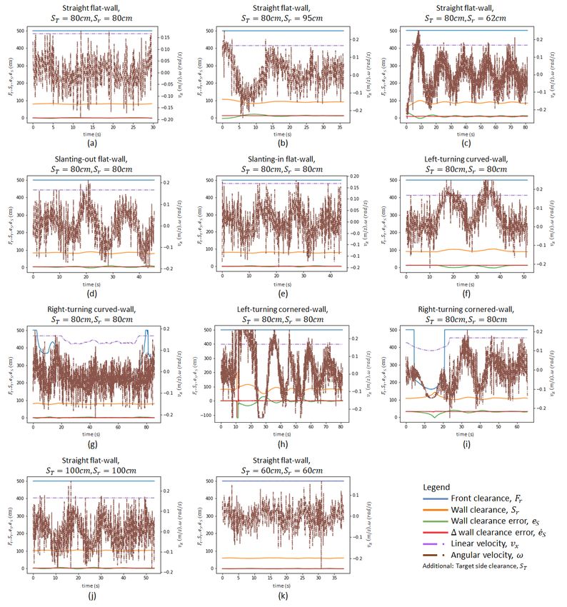
Sensors 2021, 21, 6096                                                                                            2 of 21

                         1.2. Existing Technologies
                         1.2.1. Disinfection Methods and Mechanism
                                Disinfection operations are creating risk for frontline workers [14] as these operations
                         are manual. Manual labourers play an essential role in this viral crisis as they are also
                         required in other parts of the pandemic management system. Hence, the challenges of
                         manual disinfection methodologies have to be readdressed and reconsidered. Automating
                         this process with robots can reduce disease transmission between healthcare workers
                         and also provide better hygiene in their environments [15–20]. To effectively disinfect
                         potentially contaminated areas, robots can serve to contribute towards an efficacious
                         containment of the infectious disease.
                                Disinfection methods are found in the literature together with the development of semi
                         and fully-teleoperated robots [21,22]; a surface disinfection robot can therefore be adopted.
                         The development of teleoperated robots may provide a telepresence for frontline workers
                         as part of a solution to reduce the risk of infection. This can be seen to be inadequate
                         in contrast to autonomous systems to ease the commitment from human operators. In a
                         combined system of a master–slave with human-in-the-loop, the system may be unstable.
                         Therefore, an autonomous disinfection robot is preferable. Comparatively, walls can be eas-
                         ily contaminated with viruses in high-risk areas such as hospitals. The disinfection process
                         should require robots to operate along the walls of high-risk indoor places autonomously.
                                Most of the literature discusses automation methods by using robots equipped with
                         sprayers or, mostly, UV lamps [16,18,21]. The exploitation of UV technologies as a method
                         for surface disinfection was highly efficient (up to 99.99 percent). One of the three main
                         classifications of UV and UV-C radiation (range 100 to 280 nm), is considered the most
                         effective disinfection class among other UV class ranges in viral inactivation as discussed
                         by Houser [23]. It is harmful to viruses and bacteria. In the case of COVID-19, UV-C
                         damages its RNA sequence, making it unable to replicate. In application, it is proportional
                         to the duration of exposure and intensity. Hence, robots can either be designed with
                         higher UV-C intensity lamps or with controlled motion time functions. UV-C equipped
                         robots are not preferable in a human-shared environment as UV-C radiation is harmful
                         to human skin and eyes. Traditional surface decontamination methods include mainly
                         fogging, fumigation, electrostatic spraying and UV light [24]. More commonly, disinfectant
                         sprayers and sanitiser dispensers are utilised in COVID-19 management [8,15].
                                Wall cleaning mechanisms are typically wall-climbing robot cleaners as compared
                         to their manipulator cleaning counterparts [25–28]. Wall robots’ mobility on the walls is
                         mostly performed via suction (either with wheel or legs), thrust or auxiliary mechanisms
                         (i.e., rope, scaffold etc.). These wall cleaners moving on vertical surfaces are constrained by
                         mostly consistent features; overcoming obstacles and intricate wall features is challenging.
                         Two-DOF manipulators were proposed; the distance and angle of the end-effectors can
                         be controlled by a ball-screws mechanism, proposed by Kim et al. [29], and by an eight
                         joint manipulator proposed by Joo et al. [30]. As end-effectors, the robot’s cleaning module
                         is typically equipped with various types and combinations of brushes, squeegees and
                         scrapers. Most suction robots are equipped with tools for dry cleaning or diatomite
                         methods, while wire/roped robots are equipped with water cleaning tools [25]. Examples
                         of common cleaning methods of cleaning robots include the TITO 500 [31] and the CAFE
                         robot [32], which use brushes and water sprays. Most of these cited works discuss the
                         development of wall cleaning robots designed for high rise buildings’ outer walls. There
                         are fewer discussions regarding the development of indoor wall cleaning robots.

                         1.2.2. Wall Following Methods
                               Autonomous wall-following ability is essential for a wall cleaning mobile robot to
                         maintain a proper clearance with the wall. Furthermore, a wall cleaning robot should have
                         the ability to work in an unknown environment. In this regard, online-decision making
                         ability is preferred over offline planners [16,33]. Therefore, the wall-following method for a
                         wall cleaning robot should have online decision-making ability.
Sensors 2021, 21, 6096                                                                                            3 of 21

                                Many popularly used general autonomy algorithms are generalized models for auton-
                         omy implementation. Some of the common algorithms are line-tracing algorithms [34,35],
                         SLAM [36,37], probabilistic [38,39] and Artificial Potential Fields [40]. These algorithms
                         may not be suitable, as trace-tracing algorithms require the set-up and maintenance of
                         visibly traceable lines, and other methods optimize the shortest path/energy approach.
                         The shortest path approach is not suited for wall-following methods as the robot should
                         aim to cover as much area as possible, and it should always be navigating down the walls
                         of the facilities closely, which is not provided by the waypoints of common approaches.
                                The use of Proportional–Integral–Derivative (PID) controllers for wall-following has
                         been studied in [41,42]. However, the targeted wall was straight, and these proposed
                         PID controllers were ineffective in coping with curved or slanted walls. Furthermore,
                         the controller gains need to be tuned for different set points, which hinders the usability
                         of a reconfigurable wall cleaning mechanism. The authors of [43,44] investigated the
                         performance of different neural networks for wall-following. The robot’s classification
                         ability corresponding to a set of sensor readings is used for the performance analysis.
                         However, the investigations are limited to validation through a dataset; no real-world
                         validation or simulation has been conducted. Therefore, the validity of the proposed
                         method is doubtful in real-world applications. In addition to that, the requirement of a
                         comprehensive dataset that covers most probable scenarios is increasingly complicated
                         and dependent on the sensor arrangement of a robot.
                                Fuzzy logic systems tuned through optimization have been widely used due to
                         their ability to cope with uncertainties. In this regard, various methods for tuning fuzzy
                         logic systems have been investigated, including ant-colony optimization [45], differential
                         evolution [46], bee-colony optimization [47,48], and reinforcement learning. Furthermore,
                         the use of interval type 2 fuzzy logic systems tuned by these techniques has also been
                         studied [49,50]. These methods are capable of effectively taking control actions to follow
                         walls after training on environments. However, the main shortcoming of these methods is
                         the requirement for retraining when changing the reference distance from the wall. Thus,
                         the methods are ineffective for a wall cleaning robot with different end-effectors where the
                         distance with the wall has to be remodelled for different tools. Furthermore, generalization
                         of the training is also a concern since it requires training in many environments.
                                Several fuzzy logic systems based on expert knowledge have been developed for the
                         wall-following features of mobile robots. The work [51] proved that a fuzzy logic system
                         could have better performance than a PID controller in terms of wall-following. Another
                         similar sort of fuzzy logic controller defined based on expert knowledge for wall-following
                         has been presented in [52]. A system consisting of three individual fuzzy logic systems
                         switched per the scenario of wall-following has been proposed in [53,54]. The system
                         analyzes the range sensor information and determines the current scenario as a straight,
                         left corner, and right corner wall. The fuzzy logic system designed for each of these
                         scenarios is then selected for generating the control action. The use of condition-based
                         fuzzy logic system selection is susceptible to sensor noises. All the fuzzy logic systems cited
                         above are capable of establishing the wall-following ability of a robot without requiring
                         training. However, all these systems are tailored for a specific clearance distance with a
                         wall, and the membership functions have to be redesigned to allow the systems to work
                         with different reference distances. Thus, the cited systems are not convenient for a wall
                         cleaning robot with a reconfigurable end-effector. The work [55] proposed a fuzzy logic
                         system that can adapt to different reference distances for a wall disinfection robot that
                         eliminates the limitations of all the other wall following methods discussed above. Hence,
                         it is the work that is most relevant for this paper. However, the scope of the work is limited
                         to simulations, and experiments with a real robot deployment have not been conducted.
                         The limitations of the existing wall-following methods discussed above are summarized in
                         Table 1.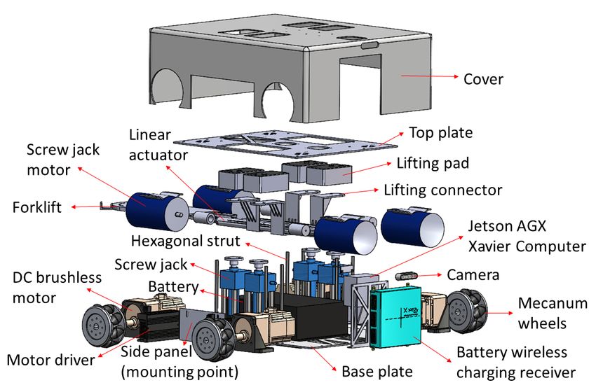
Sensors 2021, 21, 6096                                                                                                   4 of 21

                         Table 1. Limitations of the existing wall following methods.

                          Method                                      Major Limitations
                                                                      Clear visible lines have to be drawn on the floor,
                          Line tracing methods proposed in [34,35]
                                                                      which is not convenient.
                                                                      Designed only for straight walls and the methods
                          PID controllers proposed in [41,42]         are ineffective in slanted or curved walls that a
                                                                      disinfection robot can often encounter.
                                                                      Validation is limited to offline classification
                          Neural network based methods proposed
                                                                      performance tests with a dataset; neither experiment
                          in [43,44]
                                                                      nor simulations were conducted for the validation.
                                                                      Retraining is required in the case of changing the
                                                                      reference distance with a wall. For a robot that uses
                          FLS tuned through metaheuristics [45–50]
                                                                      various disinfection tools, it is essential to have the
                                                                      flexibility to change the reference distance.
                                                                      The methods are designed to maintain only a
                                                                      specific reference distance with a wall. In the case of
                                                                      altering the reference distance, the membership
                          FLS proposed in [51–54]
                                                                      functions of the FLS should be redesigned. Thus,
                                                                      the methods are not convenient for a robot intended
                                                                      to operate with various reference distances.
                                                                      Validation is limited to simulations using a generic
                          FLS proposed in [55]
                                                                      robot model.

                         1.2.3. Reconfigurable Robotics
                               The trend of reconfigurable robots is increasing as they are set to provide high versatil-
                         ity of functions by adopting various shapes and forms. The types and range of applications
                         can vary to fit the demands of users. This makes them highly attractive to facilities
                         managers of, for example, hospitals and airports, due to the high cost–benefit ratio. Re-
                         configuration [56] can be classified in three ways; intra-, inter-, or nested-reconfiguration.
                         Intra-reconfigurable robots possess the ability to transform internally without involving any
                         additional module, while inter-reconfiguration may consist of the assembly or reassembly
                         of homogeneous or heterogeneous robot modules as a single unified platform. Nested-
                         reconfigurable robots involve both intra- and inter-reconfigurable functions integrated into
                         a single robot platform.
                               Adopting inter-reconfigurable robots is advantageous for hospitals where robot plat-
                         forms can converge into a single platform with inter-reconfigured modules for different
                         applications. Autonomous reconfigurable partners can help to ease hospital operations
                         for staff and include more value-adding tasks into the scope of their jobs. Reconfigurable
                         robots have yet to fulfil the promise of versatility [57,58]. It has been implied in studies
                         that reconfiguration has to be useful for end-users for it to be considered versatile.

                         1.3. Aims and Contributions
                               This paper presents and proposes the implementation of an autonomous wall-following
                         ability in a reconfigurable wall-cleaning robot. The aim of the proposed solution is to,
                         firstly, unveil a new autonomous inter-reconfigured robot application to a hospital robot’s
                         range of versatility and, secondly, a proof of real-world integration that has not previously
                         been established. Prior to this development, the algorithm had not been tested or verified
                         in any physical robot platform. Real-world application refers to the physical validation
                         of the usability of the methodological approach and the appropriate use of the approach.
                         In this paper, the practical use of the approach is in the context of disinfection operations.
                         The physical robot is to be observably moving along a targeted wall while maintaining a
                         fixed distance. The wall-following algorithm is a Fuzzy Logic System (FLS) that dictates the
                         robot’s reference linear and angular velocities during operations. The proposed exploita-
                         tion of this method is to enable robots for wall-cleaning or disinfection tasks to be used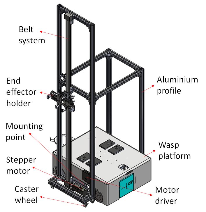
Sensors 2021, 21, 6096                                                                                              5 of 21

                         in public areas at high risk of contaminants. The experiments have considered a range of
                         typical wall features and evaluate the capabilities of the robot’s wall-following behaviours.
                              The following sections of the paper include a technical introduction of the utilized
                         robot platform and wall-following methodology in Sections 2 and 3. Subsequently, in
                         Section 4, the paper details the experimental set-up then presents the experimental results
                         and discussions. The paper concludes the research findings in adopting the autonomous
                         function in robot mobility for wall-following in Section 5.

                         2. Robot Platform
                         2.1. Overview
                               In this paper, the Wasp platform is equipped to demonstrate the wall-following
                         behaviour, specifically in the example of wall cleaning by integrating a wall cleaning
                         module into the platform. This section briefly describes the motivation behind the Wasp
                         platform, followed by the mechanical design, electrical system, and kinematics modelling
                         of the Wasp platform.
                               Firstly, Wasp is a robot that is expected to be developed into a highly versatile robot
                         platform in healthcare settings in collaboration with Changi General Hospital (CGH) in
                         Singapore. With the ability to reconfigure, the application of Wasp can be, but is not limited
                         to, patient handling, logistics, cleaning and surveillance. One exemplary application of the
                         Wasp platform is to be utilized as a logistic robot to transport different types of trolleys
                         after reconfiguration. Presently, numerous robots from different developers have been
                         utilized in CGH, each with its rated payload and dimensions, mainly to automate the
                         trolley transportation process. However, due to product diversification, each of these
                         robots has its unique specification, communication protocols and charging platforms,
                         which exponentially reduce the ease of centralized management of these robots. What is
                         more, these robots are designed as a single module to operate independently with their
                         distinct mechanism. In other words, each of these robots has limited capability to handle a
                         particular type of trolley, and different robots are needed for different types of trolleys. As a
                         result, the demand for robots with different specifications and functions is overwhelming,
                         and this opposes the economic benefits as more efforts and resources are needed to manage
                         these robots. Under such circumstances, nested-reconfigurable robots are recommended.
                               Research on reconfigurable robots was initiated in the 1980s. It originated from modu-
                         lar robotics, which refers to a family of robotics systems made of interconnected individual
                         robots. These individual robots, also referred to as modules, are relatively small in size
                         and are able to perform tasks independently. Currently, this area is progressing in auton-
                         omy development. When needed, these robots can be interconnected (module-to-module)
                         through docking interfaces to form a larger physical structure and gain the advantage of
                         size to cope with physically larger tasks. The ability of these modular robots to morph into
                         different structures has earned themselves the name of reconfigurable or self-reconfigurable
                         robots, depending on the autonomy level associated with the process [59,60]. Traditionally,
                         reconfigurable robots used to be classified into lattice, chain and hybrid types until a
                         group of researchers proposed a new classification concept, the intra-, inter- and nested-
                         reconfigurable robots in [56]. Intra-reconfigurable robots possess the ability to transform
                         internally without involving an external module, while inter-reconfigurable robots have the
                         ability to assemble external modules to form a new robot. Nested-reconfigurable robots in-
                         volve both intra- and inter-reconfigurability being integrated into the same robot. With the
                         promise of a high degree of versatility, robustness and modularity, nested-reconfigurable
                         robots would be an ideal solution to the dynamic demands of a typical healthcare envi-
                         ronment. Thus, the Wasp platform is designed as a nested-reconfigurable robot; not only
                         is it expected to transport different types of trolleys after intra-reconfiguration, but also
                         to perform other specific tasks such as wall cleaning after inter-reconfiguration with an
                         external wall cleaning module.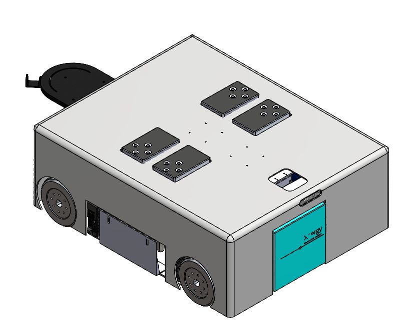
Sensors 2021, 21, 6096                                                                                         6 of 21

                         2.2. Mechanical Design
                               As shown in Figure 1, the Wasp platform has a rectangular geometry. Internally, its
                         mainframe is comprised of a top plate and a base plate, both made of stainless steel. Ten
                         hexagonal struts are used to connect the top and base plates to create a clearance height of
                         266 mm to accommodate both mechanical and electrical parts of the platform. Referring
                         to Figure 2, there are four units of screw jack with motors and a unit of forklift attached
                         to a linear actuator for the lifting mechanism and towing mechanism, respectively. These
                         two mechanisms enable the platform to be intra-reconfigurable to handle different trolley
                         types in CGH. In lifting mode, the Wasp platform lifts the trolleys with sufficient ground
                         clearance from underneath using screw jacks. Meanwhile, in towing mode, the Wasp
                         platform tows the trolleys with smaller ground clearance using the forklift extended out of
                         the robot body as shown in Figure 1. Besides, four Mecanum wheels are used for robot
                         locomotion due to their high manoeuvrability. By driving these wheels with different
                         combinations of speed and direction using DC brushless motors, the Wasp platform is
                         able to move freely in any direction at any instance without changing its orientation. Such
                         omnidirectional mobility allows the platform to perform tasks effectively in constrained
                         environments (i.e., obstacles and narrow spaces) [61].

                         Figure 1. External view of Wasp platform.

                         Figure 2. Exploded view of Wasp platform.

                              The exploded view in Figure 2 shows a side panel available in the Wasp platform
                         as a mounting point for an external module. In this paper, a wall cleaning module is
                         particularly described to assist in demonstrating the wall-following behaviour of the Wasp
                         platform. As shown in Figure 3, the wall cleaning module framework is constructed using
                         aluminium profiles while caster wheels are used for its mobility. Furthermore, a belt
                         system is adopted vertically for the up-down movement of the end-effector, with the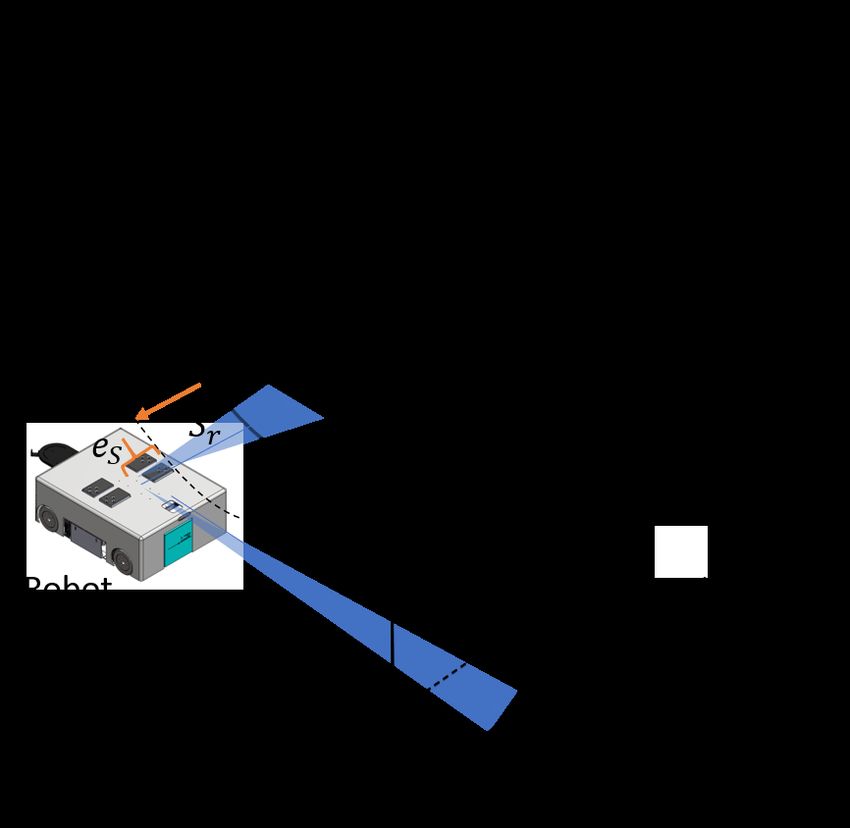
Sensors 2021, 21, 6096                                                                                         7 of 21

                         end-effector holder installed on the belt system table. Figure 3 also shows an illustration
                         of the wall cleaning module mounted on the platform. Additional and other on-board
                         functions and design architecture are not further elaborated, given the scope of this paper.
                         The assembly of this external wall cleaning module onto the Wasp platform demonstrates
                         the inter-reconfigurability of the Wasp platform as mentioned earlier.

                         Figure 3. Integration of wall cleaning module with Wasp platform.

                         2.3. Power System and Electronics
                               As shown in Figure 4, the Wasp platform carries a rechargeable 16-cells Lithium-ion
                         battery as its main power supply. This battery supplies 48VDC to the platform and is
                         charged wirelessly using the Xnergy wireless charging panel. Wireless charging mode with
                         fast charging technology from Xnergy enable the Wasp platform to be fully charged in
                         50 min, and at the same time, it is free from the need for precise docking required by wired
                         connecting chargers. Next, to power up the electronics with different power ratings, voltage
                         regulators are used to step down 48 V to several voltage levels such as 24 V, 19 V and 12 V.
                         Within these electronics, Roboclaw controllers (Roboclaw 2×15A Dual Channel Motor
                         Controller, https://www.basicmicro.com/RoboClaw-2x15A-Motor-Controller_p_10.html
                         accessed on 3 September 2021) are used to power and control the screw jack motors (Jac-
                         ton 24 V DC motor with JTC series screw jack, part number JTC5-UK-70-H-I-C-PP, http:
                         //www.jacton-screwjacks.com/web/2018/JTCSeriesCubicScrewJacks_1114/238.html ac-
                         cessed on 3 September 2021) and the linear actuator (12” Mini Linear Actuator, https:
                         //www.firgelliauto.com/products/mini-linear-actuator accessed on 3 September 2021) for
                         the lifting and towing mechanisms, respectively, while Oriental motor controllers are used
                         to power and control the Oriental brushless motors (BLV640NM50S, 400W(1/2 HP) Brush-
                         less DC Motor Speed Control System, https://catalog.orientalmotor.com/item/blv-series-
                         brushless-dc-motor-speed-control/400w-blv-series-brushless-dc-motors/blv640nm50s-3
                         accessed on 3 September 2021) to drive Mecanum wheels for Wasp platform locomotion.
                         On the other hand, an Nvidia Jetson AGX Xavier computer is used as the central pro-
                         cessing unit for its capability for graphics processing. Ubuntu 16.04 LTS is installed as
                         the operating system while Robot Operating System (ROS) is used as the framework
                         for writing the robot software. Specifically, a custom made Microsoft C++ code is im-
                         plemented to run the proposed FLS in this study. LiDAR readings are collected and
                         segmented into two main inputs for FLS, which then outputs command velocity to control
                         the motion of the robot platform. Lastly, the Vectornav IMU sensor (VectorNav VN-
                         100, https://www.vectornav.com/products/detail/vn-100 accessed on 3 September 2021),
                         SICK LiDAR (SICK 2D LiDAR sensor TiM581-2050101, https://www.sick.com/be/en/
Sensors 2021, 21, 6096 8 of 21
detection-and-ranging-solutions/2d-lidar-sensors/tim5xx/tim581-2050101/p/p619344 ac-
cessed on 3 September 2021) and Intel RGB camera (Intel® RealSense™ Depth Camera
D435i, https://store.intelrealsense.com/buy-intel-realsense-depth-camera-d435i.html ac-
cessed on 3 September 2021) are connected to the computer for Wasp platform orientation,
navigation and vision purposes, respectively.
Figure 4. Electrical system diagram of Wasp platform.
2.4. Kinematics Modeling
As a typical four-wheel Mecanum drive robot, the kinematics model of the Wasp
platform is shown in Figure 5. The symbols are defined as below:
• X, G, Y: The inertial frame.
• xr , or , yr : The Wasp platform base frame. or is the center of robot base.
• xwi , owi , ywi : The coordinate system of ith wheel. owi is the wheel center point.
• αi : The angle between or owi and xr .
• β i : The angel between xwi and ywi .
• γi : The angle between vir and viw .
• vir : The velocity of passive rollers in ith wheel.
• viω : The velocity of ith wheel correspond to wheel revolution.
• lix : Half the distance between front wheels or rear wheels.
• liy : Half the distance between front wheel and rear wheel.
• v x : Longitudinal velocity of Wasp platform.
• yy : Transversal velocity of Wasp platform.
• ωz : Angular velocity of Wasp platform.
Assuming that wheel slippage on the ground is negligible, and all the wheels are the
same size with radius r, the inverse kinematics equation of the Wasp platform is shown in
Equation (1), while the forward kinematics equation is shown in Equation (2), with T + as
the transpose matrix of the Jacobian matrix of the inverse kinematics equation.
cos( β 1 −γ1 ) sin( β 1 −γ1 ) l1 sin( β 1 −γ1 −α1 )
ω1 cossin γ1 sin γ1 sin γ1
ω2 − 1 ( β2 −γ2 ) sin( β2 −γ2 ) l2 sin( β2 −γ2 −α2 ) v x
= sin γ2 sin γ2 sin γ2
vy (1)
ω3 r cos( β3 −γ3 ) sin( β3 −γ3 ) l3 sin( β3 −γ3 −α3 )
sin γ3 sin γ3 sin γ3 ωz
ω4 cos( β 4 −γ4 ) sin( β 4 −γ4 ) l4 sin( β 4 −γ4 −α4 )
sin γ4 sin γ4 sin γ4Sensors 2021, 21, 6096 9 of 21
ω1
vx ω2
+
vy = T
ω3 (2)
ωz
ω4
Figure 5. Kinematics model of Wasp platform.
Table 2 below presents the parameters of the Wasp platform (refer to Figure 5). By sub-
stituting and deriving (1) and (2), the inverse kinematics are given in (3) while the forward
kinematics are given in (4).
−1 −(lx + ly )
ω1 1
vx
ω2
= − 1 1 1 ( l x + ly )
vy
(3)
ω3 r 1 1 −(lx + ly )
ωz
ω4 1 −1 ( l x + l y )
ω
1 1 1 1 1
vx
vy = r
ω2
− 1 1 1 −1
(4)
4 − 1
1
− (lx +1 ly ) 1
. ω3
ωz ( l x + ly ) ( l x + ly ) ( l x + ly ) ω4
Finally, (5) gives the angular velocity of each wheel, while (6)–(8) provide the longitu-
dinal velocity, transversal velocity and angular velocity of the Wasp platform, respectively.
1
ω1 = ( v x − vy − ( l x + ly ) ωz )
r
1
ω2 = ( v x + v y + ( l x + l y ) ω z )
r (5)
1
ω3 = ( v x + v y − ( l x + l y ) ω z )
r
1
ω4 = ( v x − v y + ( l x + l y ) ω z )
r
r
v x (t) = ( ω + ω2 + ω3 + ω4 ) (6)
4 1
r
vy (t) = (−ω1 + ω2 + ω3 − ω4 ) (7)
4
r
ωz ( t ) = (−ω1 + ω2 − ω3 + ω4 ). (8)
4( l x + l y )Sensors 2021, 21, 6096 10 of 21
In this paper, the v x , vy and ω of the Wasp platform are given by the output of FLS,
which will be further explained in the latter part. Through inverse kinematics equations,
the angular velocity of each wheel is generated according to FLS output, which then drives
the platform following the wall according to FLS control.
Table 2. Parameters of the Wasp platform.
i αi βi γi li lix liy
1 π
4
π
2 − π4 l lx ly
2 − π4 − π2 π
4 l lx ly
3π π π
3 4 2 4 l lx ly
4 − 3π4 − π2 − π4 l lx ly
3. Wall-Following Method
3.1. Overview
A scenario of the robot following a curvy wall with a right-handed corner is depicted
in Figure 6. It is assumed that the cleaning unit is fixed on the robot’s left side, and the robot
follows the wall from the left. The target side clearance for a particular cleaning application
and a tool can be defined by the user (denoted as ST ). The robot is expected to follow a
path that has the target clearance distance with the wall throughout the course. The current
side clearance range of the robot with the wall is measured from the Lidar sensor as Sr .
In this regard, the minimum reading within a 40◦ window on the left side is considered.
Similarly, the free-range from the front is measured as Fr , considering a 10◦ window in the
front. The error between the target side clearance (i.e., ST ) and the current side clearance,
measured from the range sensor (i.e., Sr ), eS , is calculated as in (9). The robot has to turn
toward or away from the wall based on the error to minimize the side clearance error (i.e.,
if eS > 0 then ω < 0 or vice versa). Furthermore, if there is a front obstruction caused by
a wall segment such as a right-turning cornered-wall, the robot has to slow down a bit
by altering the front linear velocity (v x ) and should turn towards the right (i.e., ω < 0) to
follow the new wall segment. The wall-following of the controller is designed to generate
the required controlling actions, v x and ω, to follow any given wall based on the sensory
information provided by the Lidar.
e S = S T − Sr . (9)
Figure 6. Overview of wall-following.Sensors 2021, 21, 6096 11 of 21
3.2. Fuzzy Logic System (FLS)
A fuzzy logic system can provide quantitative values for a qualitative linguistic
input. Mainly, it can map the input for an output space by a set of linguistic rules [62,63].
Fuzzy logic can apply in a situation where the robot perceives the environment data and
makes decisions according to the changes in the environment. Further, fuzzy logic is
a reliable modelling method for complex robotics systems or systems without realizing
specific underlying dynamics [64,65]. The environment and exact dynamics of the robot are
uncertain in a situation where the robot is following a wall. Furthermore, these uncertainties
increase with the reconfiguration. Expert knowledge of linguistic expressions can be used
for the control actions for a wall-following behaviour [66]. Moreover, sensory information
obtained from the Lidar readings of the robot may include noises and might not be accurate.
According to the literature, fuzzy logic is an excellent solution to provide control actions
where the sensory information is vague [67,68] and for unknown environments [66,69].
Therefore, fuzzy logic is used in this paper to achieve the wall-following behaviour for
the robot.
The architecture of the fuzzy logic system for the proposed method is shown in
Figure 7. The inputs for the Fuzzy Logic System (FLS) are the side clearance error of the
robot (i.e., eS ), the rate of change of the side clearance error with the wall (i.e., ėS ), and free
front range (i.e., Fr ) for the robot to navigate. Linear velocity (i.e., v x ) and angular velocity
(i.e., ω) are the outputs of the FLS. To cope efficiently with uncertainties, non-singleton
fuzzy sets have been specified for the input membership functions in the FLS [70]. Input
membership functions are given in Figure 8a–c for eS , ėS , and Fr , respectively. The fuzzified
values for the inputs are represented as µeS (eS ), µėS (ėS ), and µ Fr ( Fr ).
Figure 7. Architecture of Fuzzy logic system.
Figure 8. (a–c) represent the input membership function for eS , ėS , and Fr , respectively. (d,e) show
the output membership function for v and ω, respectively. Fuzzy labels are defined as NL: ‘Negative
Large’, N: ‘Negative’, Z: ‘Zero’, P: ‘Positive’, PL: ‘Positive Large’, C: ‘Close’, M: ‘Moderate’, F: ‘Far’, L:
‘Low’, M: ‘Moderate’, H: ‘High’. The membership functions are defined in normalized scale.Sensors 2021, 21, 6096 12 of 21
The set of linguistic rules used for mapping the input and output is depicted in Table 3.
The output membership functions are given in Figure 8d,e for v x and ω, respectively.
Furthermore, the necessary control actions are deduced in this step. The firing strength of
ith rule, αi can be inferred as given in (10) with max and min operators as t-conorm and
t-norm, respectively.
By using the Mamdani implication method, the consequents of the output fuzzy sets
corresponding to the ith rule can be obtained as in (11). Here, µv0x and µω 0 are the fuzzy
i i
consequents of the outputs v x and ω, respectively. The fuzzy aggregation operator, max, is
used to combine these fuzzy consequents into a single set for each output as given in (12).
The FLS should provide crisp control outputs to control the robots reference linear
and angular velocities (v x and ω) for the effective wall-following cleaning. These crisp
outputs could be obtained by (13) using the center of area method for the defuzzification.
αi = min{µeS (eS ), µėS (ėS ), µ Fr ( Fr )} (10)
i i i
µv0x (v x ) = min{αi , µvxi (v x )}
i
(11)
µω 0 (ω ) = min{αi , µωi (ω )}
i
µv0x (v x ) = max{µv0x (v x ), µv0x (v x ), .., µv0x (v x ), .., µv0x (v x )}
1 2 i N
(12)
µω 0 (ω ) = max{µω 0 (ω ), µω 0 (ω ), .., µω 0 (ω ), .., µω 0 (ω )}
1 2 i N
R
vµv0x (v x )dv
vx ∗ = R
µv0x (v x )dv x
R (13)
ωµ 0 (ω )dω
ω∗ = R ω .
µω 0 (ω )dω
Table 3. Rule base of the FLS.
e˙S \eS NL N Z P PL
ω = PL ω = PL ω = PL ω=P ω=Z
NL
v=H v=H v=H v=H v=H
ω = PL ω = PL ω=P ω=Z ω=N
N
v=H v=H v=H v=H v=H
Fr = F ω = PL ω=P ω=Z ω=N ω = NL
Z
v=H v=H v=H v=H v=H
ω=P ω=Z ω=N ω = NL ω = NL
P
v=H v=H v=H v=H v=H
ω=Z ω=N ω = NL ω = NL ω = NL
PL
v=H v=H v=H v=H v=H
ω=N
Fr = M
v=M
ω = NL
Fr = C
v=L
4. Results and Discussion
4.1. Experiment Setup
In order to examine the wall-following behaviour, experiments were conducted with
different types of wall conditions using the same Wasp platform. Throughout these
experiments, the Wasp platform was following the wall on its left, and ST was maintained
at 80 cm unless further indicated for the ease of data analysis and the comparison between
different experiments. Three types of walls—as shown in Figure 9, the flat-wall, the curved-Sensors 2021, 21, 6096 13 of 21
wall and the cornered-wall—were used to demonstrate the wall-following behaviour of the
Wasp platform. Although flat walls and right corners are most common, variations of walls
are important to be considered for it to be pragmatically implemented in an actual hospital.
Unconventional architectural design is not absent in the modern world; hence it improves
the autonomy of robots. Doors can be treated similarly to flat walls, but transparent features
are not detectable by LiDAR. In this proposal, the exploration of a suitable sensing method
is not part of the scope of this study.
To qualify the algorithm’s function, the input data will evidently show that the corre-
sponding output data must react based on the intended logic of the algorithm. Secondly,
the physical platform must not encounter any collision in its working environment. Lastly,
the values of the logged data are evaluated against a threshold for its fault tolerance.
The error tolerance is determined by the reach of the cleaning module. These aspects of the
robot and the algorithm will serve as qualifiers to the system.
The conditions of the experiment will be set by the characterisation of the wall,
the initial side clearance from the wall plane and set desired side clearance. First, during flat-
wall experiments, the impact of the initial robot position was investigated by locating the
platform at a distance away from a straight flat-wall, the same as ST , further than ST
and closer than ST , respectively, at the beginning of the experiments. More experiments
were then conducted at a slanted flat-wall to observe the wall-following behaviour when
there is a change of angle at the wall. Next, for both curved-wall and cornered-wall,
experiments on both left-turning and right-turning directions were conducted. Lastly,
experiments were carried out with ST at 100 cm and 60 cm to verify the robot wall-following
ability at different ST . The validation of these experiments assumes that the parameters
of the FLS are suitably tuned and adjusted based on the given platform and operating
environment. The experimental data and analysis are presented in the following section. An
explanatory video that demonstrates the experiments is given as a multimedia attachment
in Supplementary Materials.
Figure 9. Different types of wall characterization considered for the experiment.
4.2. Results Analysis
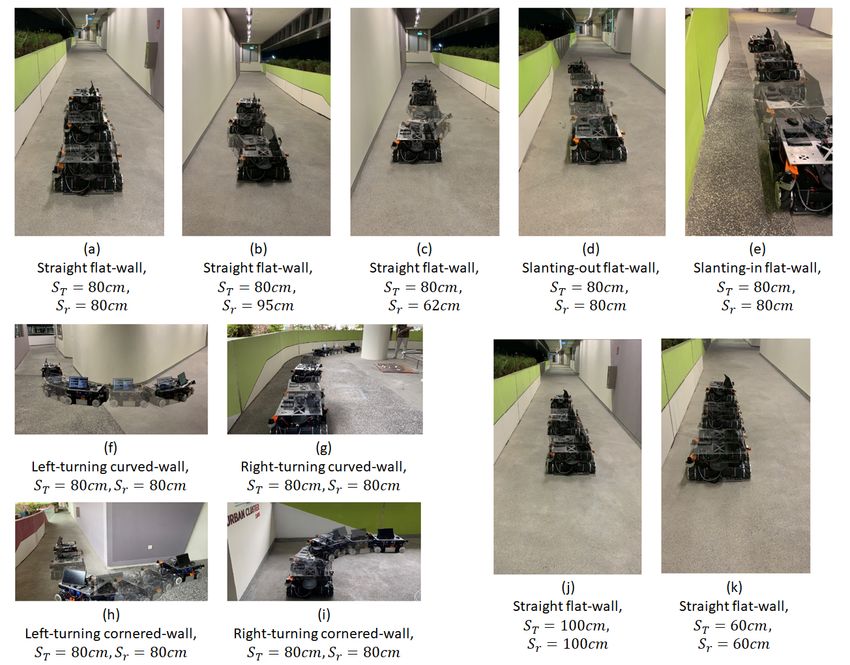
The first set of experiments was conducted to observe the effect of the robot’s initial
position on its wall-following behaviour. When the initial robot position was significantly
close to the intended ST , the platform was able to perform the wall-following with eS
oscillating within the range of ±3 cm as shown in Figure 10a. The oscillations were consid-
erably small (maximum = 2.5 cm, average = 0.95 cm). These oscillations are considered
insignificant for the wall cleaning applications as these oscillations can be coped with by
the end-effector. Figure 11 shows the robot’s motion trajectory in seven-frame time-lapse
illustrations for all the experiments. From Figure 11a, we can see that the robot’s trajectory
first encountered minor swaying and was then able to proceed in a stable trajectory along
the wall. In contrast, two cases were considered with the initial robot position offset away
from ST , with one case set further away from the wall at 95 cm and the other set closer to
the wall at 62 cm. Both measurements are relative distances from the wall to the robot base
frame. As shown in Figure 11b,c, the platform was oscillating about ST from the beginning
of both experiments. These oscillations gradually decreased in magnitude and converged
towards zero. As shown in Figure 10b,c, the robot’s angular velocity, ω, fluctuated when eS
was large and slowly stabilised towards zero as eS converged towards zero. This data trend
proves that the wall-following behaviour is well regulated by eS to achieve ST throughSensors 2021, 21, 6096 14 of 21
manipulating the robot’s angular velocity, ω. The platform oscillated between 6.5 cm
and 3.5 cm for slant-in and slant-out flat-walls in the experiments conducted with slanted
walls, respectively. On average, the oscillations were 2.6 cm for the slant-in flat-wall and
1.5 cm for the slant-out flat-wall. The experimental data for slanting-walls are presented
in Figure 10d,e. Figure 11d,e show that both experiments encountered relatively large
oscillations when the robot was transiting between different wall surfaces. However, these
oscillations progressively stabilised to a stable trajectory along the wall. These experiments
evidently verified that the platform’s wall-following behaviour is able to operate on straight
flat-walls and flat-walls with slanted features.
Figure 10. Variation of crucial parameters of the controller. (a–c) show flat-walls experiments with different initial positions,
(d,e) for slanting-wall experiments, (f,g) for curved-wall experiments, (h,i) for cornered-wall experiments, (j,k) for flat-wall
experiments with different target side clearance.Sensors 2021, 21, 6096 15 of 21
Figure 11. Robot motion trajectory in seven-frame time-lapse illustration. (a–c) show flat-wall experiments with different
initial positions, (d,e) for slanting-wall experiments, (f,g) for curved-wall experiments, (h,i) for cornered-wall experiments,
(j,k) for flat-wall experiments with different target side clearance.
For curved-wall experiments, robot wall-following behaviours at left-turning and
right-turning curved-walls were both considered. As shown in Figure 10f, the robot’s
angular velocity, ω, increased to 0.2 rad/s when eS was at negative values. Given that
eS = ST − Sr , a negative value eS indicated that the Wasp platform was further away
from the wall than ST , thus inducing a positive angular velocity, ω, to drive the robot
towards the left. Figure 11f shows the Wasp platform was turning left, following the
wall. After navigating past the curved feature, the platform was able to follow the wall
at ST (preset at 80 cm). On the other hand, the experimental data for a right-turning
curved-wall are shown in Figure 10g. As the robot turned right, the targeted wall segment
was perceived as an obstacle in front of the robot. It is evident in the graph (Figure 10g)
that the front clearance decreased, which led to a reduction of the robot’s velocity, v x .
Concurrently, a negative angular velocity, ω, was induced to turn the robot clockwise to
avoid crashing into the wall in front. The gradual variation of eS caused a relatively stable
angular velocity, ω. Figure 11g shows the Wasp platform proceeded in a right turning
trajectory following the right-turning curved-wall. The outcome of these two experiments
validates the wall-following capability in managing curved-walls.Sensors 2021, 21, 6096 16 of 21
The cornered-wall experiments time-lapse illustrations are shown in Figure 11h,i.
The experimental data in Figure 10h show that the behaviour of the robot’s linear velocity,
v x , during the left-turning cornered-wall experiment is similar to that in the left-turning
curved-wall experiment. The robot’s linear velocity, v x , was constant as there was no
obstruction detected in front of the robot while the robot’s angular velocity, ω, induced
by the variation of eS , played a role in regulating Sr according to ST . For the right-turning
cornered-wall, the experimental data shown in Figure 10i show that as Fr decreased when
the robot detected the wall segment in front as an obstruction, the robot linear velocity,
v x , decreased to slow down the robot’s movement. At the same time, the angular velocity,
ω, was at a negative value to drive the robot towards the right even though eS was at a
negative value. This phenomenon is caused by the rules defined in fuzzy logic where
priorities are appropriately set to react to Fr before Sr for collision avoidance.
In addition, to ensure the robot wall-following can handle different ST , experiments
were conducted with ST at 100 cm and 60 cm, respectively, with flat-walls. Figure 10j,k
show the experimental data, which are similar to those of the experiment with ST set
at 80 cm. Figure 11j,k show that the platform followed the wall with ST set at 100 cm
and 60 cm, respectively. These experiments proved that the wall-following algorithm is
operational at different ST , which increases its flexibility for various mounted equipment.
In general, the proposed controller was capable of following various common walls,
as seen in the experiments above. The different experimental conditions have covered
most of the possible scenarios in real life. As the straight flat-wall experimental results
show, the controller performed the best with the least oscillation when initial Sr = ST ,
therefore it is advisable to start the cleaning operation of a wall cleaning robot after it moves
to the preset wall clearance. The other experiments, which included slanting flat-wall,
curved-wall and cornered wall, on the other hand, showed the versatile adaptability of the
robot on different types of wall features. Hence, the proposed FLS controller is suitable to
utilize for wall-following robots as the experimental results above qualify its capabilities.
4.3. Discussion
The existing wall following methods based on PID controllers [41,42] are only effective
on straight walls. In contrast, experimental results obtained by deploying the robot to
slanted, curved, and cornered walls (i.e., cases (d)–(i)) showed the effectiveness of the
proposed controller for non-straight walls. Furthermore, FLSs [45–54] used in the existing
methods are designed to work with a specific reference distance, where the FLSs have to be
tuned or tailored to work with various reference distances. On the other hand, the method
proposed in this paper is capable of working with various reference distances without
requiring modifications. This ability of the controller could be noted from the experiment
cases (a), (j), and (k), where the robot was operated with three different reference distances.
These facts revealed the superiority of the proposed controller over the existing methods.
Quantitative comparison of the experimental results of the method against the results
of the existing method could provide many insights. To perform a proper quantitative
comparison, the existing methods considered for the comparison should be implemented,
and the same set of experiments should be conducted considering all the methods. How-
ever, in this particular case, such a comparison was not feasible since the FLSs based
on expert knowledge (e.g., [51–54]) have been designed to work on a specific reference
distance with a wall and a common reference distance across all the methods could not
be considered for performing a proper comparison. Furthermore, some of the existing
methods utilize parameters specific to the hardware platform. For example, the outputs
of the controllers proposed in Reference [51,52] are defined as the PWM for the motors.
In some cases, the methods require robot platforms with specific sensor arrangements that
could not be facilitated in the hardware platform used in this work. Thus, such methods
could not be mapped to the robot platform used in this work for reimplementation. These
were the reasons for limiting the comparison to a qualitative comparison.Sensors 2021, 21, 6096 17 of 21
In this study, the paper considers all types of wall that a robot frequently encounters
and/or might encounter. A graph of es root mean square (RMS) value against different wall
characterizations is plotted in Figure 12 to provide a clearer insight into the performance of
the FLS proposed in this paper. The wall characterizations considered in the experiments
are categorized into flat-wall, slanting flat-wall, curved-wall and cornered-wall. In the
flat-wall category, the RMS value is generally below 2.5 cm. Exceptions are found in cases
FW62 and FW95, yet this is explainable as these two experiments were begun with an error
to prove the capability of the proposed FLS in wall-following behaviour. As shown in
Figure 10b,c, es converged to zero towards the end of the experiments. In the slanting flat-
wall category, the RMS value is relatively high compared to FW80, FWT60 and FWT100 in
the flat-wall category. This is due to the variation of es when the robot platform encountered
a change of wall angle (see Figure 10d,e) and eventually es converges to zero towards the
end of experiments. Thus, it can be concluded that, for flat-wall characterization including
slanting flat-wall, the proposed FLS is capable of, firstly, correcting the distance between
the wall and the robot platform from an error distance to the target distance, and secondly,
controlling the robot platform to follow the wall at the desired target distance with an error
distance of not more than 5 cm.
Figure 12. Graph of es RMS value against different wall characterizations.
For curved-walls and cornered-walls, the RMS value shows an increasing trend
compared to flat-walls. Throughout both curved-wall and cornered-wall categories, left-
turning cases have a higher RMS value compared to the right-turning cases. This is due to
the working concept of the FLS and the position of the end-effector. In this paper, the end-
effector is assumed to be attached to the left side of the robot platform. Hence, the proposed
FLS will always attempt to drive the robot following the left side wall with a preset target
distance. In such a configuration, es always tends to increase during a left-turning case and
decrease during a right-turning case. The robot platform also tends to travel with a slower
velocity v x in right-turning cases due to the detection of the wall segment in front as an
obstruction, which allows more time for the robot platform to react to es . On the other hand,
cornered-wall cases have the highest RMS value among all cases as the robot platform does
not travel entirely according to the wall characterization. Instead of following the wall
in a 90◦ trajectory turn at the corner, the robot platform travelled in an arc trajectory as
shown in Figure 11h,i. Eventually, a large es value was generated at the corner position
and contributed to the high RMS value. Future work is to be carried out to further adapt
the proposed FLS to cornered-walls.Sensors 2021, 21, 6096 18 of 21
Overall, it has been shown that the proposed FLS is capable of driving the robot
platform following the wall with an es RMS value of not more than 10 cm. This es RMS
value can be coped with by means of end-effector, for example, a preloaded spring system,
to ensure the end-effector is in contact with the wall during the disinfection process. At the
same time, it has also been shown that the proposed FLS is capable of regulating the es
value towards zero when the robot platform encounters a change in the wall arrangement,
for example, a curved-wall or a cornered-wall.
5. Conclusions
In the current SARS-CoV-2 pandemic crisis, autonomously operated robots are in
high demand. Robots are known to effectively improve the containment of viruses and
reduce the risk to frontline and healthcare workers by disinfecting high-risk environments.
The targeted area in high-risk environments, such as airports, public transport areas and
hospitals, was identified as being the walls of indoor environments. This paper introduces
a novel application in inter-reconfiguration and a suitable design of autonomous control
for wall disinfection. The inter-reconfigured cleaning modules may vary. Wall-following
abilities are considered advantageous for the adoption of autonomous machines. This
addresses the demands of disinfecting the public environment. The mounted end-effector
can vary from anti-viral sprayers, UV-C lamps to mechanical cleaning mechanisms. For a
robot to perform efficaciously and to adequately engage with such equipment properly,
the navigating motion trajectory of the robot base must be able to move along the surface
of a wall at a prescribed distance that is to be maintained. This paper presented the
development of a reconfigurable wall cleaning mobile robot equipped with wall-following
capability. Wasp has demonstrated the application of inter-reconfiguration for disinfection
purposes and validated the physical development of FLS wall-following capabilities.
Wasp is a highly versatile robot platform that is currently under development for
healthcare settings. Wasp will be utilized with various end-effectors providing flexibility in
the choice of disinfection method. The wall following algorithm is portable, such that a typ-
ical mobile robot can adapt the algorithm for wall-following. In this study, the integration
of real-world applications was enabled by the functions of inter-reconfiguration and the
FLS wall-following algorithm cohesively. This system can help manage public health and
safety during the current pandemic and for future safeguarding. The robot is not limited
to use in hospitals but could also be used in other public environments regardless of risk
levels. The platform has adopted the proposed FLS wall-following behaviour by reading
front and side clearances alongside numerically processed errors. With proper adjustments
of the algorithm’s sensitivity, the platform is proven to be capable of wall-following with
seven types of different wall features and has additionally been tested with varying offsets
for its initial starting point. The robot was successful in managing its trajectory even with
different targeted side clearances.
Throughout the experiments, the oscillating errors of the robot trajectory encountered
are reasonable and considered negligible. The platform has fulfilled the promise of versatil-
ity. Real-world implementation of the proposed wall-following method was verified and
proven in the scope of this research. The evaluation of the cleaning efficiency and energy
usage of the robot is to be explored in future work.
Supplementary Materials: The following are available online at https://www.mdpi.com/article/10
.3390/s21186096/s1.
Author Contributions: Conceptualization, M.A.V.J.M. and M.R.E.; methodology, C.G.M., S.M.B.P.S.
and M.A.V.J.M.; software, A.W.Y.S., C.G.M. and M.A.V.J.M.; validation, W.A.Y.S. and C.G.M.; writing—
original draft preparation, A.W.Y.S., C.G.M. and S.M.B.P.S.; writing—review and editing, M.A.V.J.M.;
visualization, A.W.Y.S. and C.G.M.; supervision, M.R.E. All authors have read and agreed to the
published version of the manuscript.Sensors 2021, 21, 6096 19 of 21
Funding: This research is supported by the National Robotics Programme under its Robotics En-
abling Capabilities and Technologies (Funding Agency Project No. 192 25 00051), National Robotics
Programme under its Robot Domain Specific (Funding Agency Project No. 192 22 00058), National
Robotics Programme under its Robotics Domain Specific (Funding Agency Project No. 192 22 00108),
and administered by the Agency for Science, Technology and Research.
Conflicts of Interest: The authors declare no conflict of interest. The funders had no role in the design
of the study; in the collection, analyses, or interpretation of data; in the writing of the manuscript,
or in the decision to publish the results.
References
1. Lotfi, M.; Hamblin, M.R.; Rezaei, N. COVID-19: Transmission, prevention, and potential therapeutic opportunities. Clin. Chim.
Acta 2020, 508, 254–266. [CrossRef]
2. Maurya, D.; Gohil, M.K.; Sonawane, U.; Kumar, D.; Awasthi, A.; Prajapati, A.K.; Kishnani, K.; Srivastava, J.; Age, A.; Pol, R.; et al.
Development of autonomous advanced disinfection tunnel to tackle external surface disinfection of COVID-19 virus in public
places. Trans. Indian Natl. Acad. Eng. 2020, 5, 281–287. [CrossRef]
3. Cai, J.; Sun, W.; Huang, J.; Gamber, M.; Wu, J.; He, G. Indirect virus transmission in cluster of COVID-19 cases, Wenzhou, China,
2020. Emerg. Infect. Dis. 2020, 26, 1343. [CrossRef]
4. Kraemer, M.U.; Yang, C.H.; Gutierrez, B.; Wu, C.H.; Klein, B.; Pigott, D.M.; Du Plessis, L.; Faria, N.R.; Li, R.; Hanage, W.P.; et al.
The effect of human mobility and control measures on the COVID-19 epidemic in China. Science 2020, 368, 493–497. [CrossRef]
[PubMed]
5. Mofijur, M.; Fattah, I.R.; Alam, M.A.; Islam, A.S.; Ong, H.C.; Rahman, S.A.; Najafi, G.; Ahmed, S.; Uddin, M.A.; Mahlia, T. Impact
of COVID-19 on the social, economic, environmental and energy domains: Lessons learnt from a global pandemic. Sustain. Prod.
Consum. 2020, 26, 343–359. [CrossRef] [PubMed]
6. Morens, D.M.; Fauci, A.S. Emerging infectious diseases: Threats to human health and global stability. PLoS Pathog. 2013,
9, e1003467. [CrossRef] [PubMed]
7. Nicola, M.; Alsafi, Z.; Sohrabi, C.; Kerwan, A.; Al-Jabir, A.; Iosifidis, C.; Agha, M.; Agha, R. The socio-economic implications of
the coronavirus and COVID-19 pandemic: A review. Int. J. Surg. 2020, 78, 185–193. [CrossRef] [PubMed]
8. Zeng, Z.; Chen, P.J.; Lew, A.A. From high-touch to high-tech: COVID-19 drives robotics adoption. Tour. Geogr. 2020, 22, 724–734.
[CrossRef]
9. Ryu, B.H.; Cho, Y.; Cho, O.H.; Hong, S.I.; Kim, S.; Lee, S. Environmental contamination of SARS-CoV-2 during the COVID-19
outbreak in South Korea. Am. J. Infect. Control 2020, 48, 875–879. [CrossRef]
10. Ye, G.; Lin, H.; Chen, S.; Wang, S.; Zeng, Z.; Wang, W.; Zhang, S.; Rebmann, T.; Li, Y.; Pan, Z.; et al. Environmental contamination
of SARS-CoV-2 in healthcare premises. J. Infect. 2020, 81, e1–e5. [CrossRef]
11. Razzini, K.; Castrica, M.; Menchetti, L.; Maggi, L.; Negroni, L.; Orfeo, N.V.; Pizzoccheri, A.; Stocco, M.; Muttini, S.; Balzaretti, C.M.
SARS-CoV-2 RNA detection in the air and on surfaces in the COVID-19 ward of a hospital in Milan, Italy. Sci. Total Environ. 2020,
742, 140540. [CrossRef] [PubMed]
12. Kass, N.; Kahn, J.; Buckland, A.; Paul, A.; Group, E.W. Ethics Guidance for the Public Health Containment of Serious Infectious Disease
Outbreaks in Low-Income Settings: Lessons from Ebola; Johns Hopkins Berman Institute of Bioethics: Baltimore, MD, USA, 2019.
13. CDC COVID-19 Response Team; Chow, N.; Fleming-Dutra, K.; Gierke, R.; Hall, A.; Hughes, M.; Pilishvili, T.; Ritchey, M.;
Roguski, K.; Skoff, T.; et al. Preliminary estimates of the prevalence of selected underlying health conditions among patients with
coronavirus disease 2019—United States, February 12–March 28, 2020. Morb. Mortal. Wkly. Rep. 2020, 69, 382–386.
14. Nyashanu, M.; Pfende, F.; Ekpenyong, M. Exploring the challenges faced by frontline workers in health and social care amid the
COVID-19 pandemic: Experiences of frontline workers in the English Midlands region, UK. J. Interprof. Care 2020, 34, 655–661.
[CrossRef]
15. Khan, Z.H.; Siddique, A.; Lee, C.W. Robotics utilization for healthcare digitization in global COVID-19 management. Int. J.
Environ. Res. Public Health 2020, 17, 3819. [CrossRef] [PubMed]
16. Wang, X.V.; Wang, L. A literature survey of the robotic technologies during the COVID-19 pandemic. J. Manuf. Syst. 2021,
60, 823–836. [CrossRef]
17. Alsamhi, S.; Lee, B. Blockchain for Multi-Robot Collaboration to Combat COVID-19 and Future Pandemics. arXiv 2020,
arXiv:2010.02137.
18. Choi, H.K.; Cui, C.; Seok, H.; Bae, J.Y.; Jeon, J.H.; Lee, G.E.; Choi, W.S.; Park, M.S.; Park, D.W. Feasibility of ultraviolet light-
emitting diode irradiation robot for terminal decontamination of COVID-19 patient rooms. Infect. Control. Hosp. Epidemiol. 2021,
1–25. [CrossRef]
19. Murphy, R.R.; Gandudi, V.B.M.; Adams, J. Applications of robots for COVID-19 response. arXiv 2020, arXiv:2008.06976.
20. Devrim, İ.; Çatıkoğlu, A.; Bayram, N. An UV disinfection robot combined cleaning and housekeeping strategy for the hospital
during COVID-19 pandemic: How we protect the hospital cleaning staff? Res. Sq. 2021, 1. [CrossRef]You can also read