HEV THERMAL MANAGEMENT OF HIGH VOLTAGE BATTERY WITH INDIRECT AIR COOLING AND REGARDING CUSTOMER PERFORMANCE - DIVA
←
→
Page content transcription
If your browser does not render page correctly, please read the page content below

DEGREE PROJECT IN VEHICLE ENGINEERING,
SECOND CYCLE, 30 CREDITS
STOCKHOLM, SWEDEN 2020

HEV thermal management of high
voltage battery with indirect air
cooling and regarding customer
performance

BENJAMIN ORTÉGA

KTH ROYAL INSTITUTE OF TECHNOLOGY
SCHOOL OF ENGINEERING SCIENCES
ABSTRACT

 The automotive environment is quickly evolving due to increasingly stringent environmental
standards and the gradual reduction of the volume of diesel motorized vehicles. The volumes of electrified
vehicles are thus constantly growing and are brought to be more and more present in our streets. This
electrification of vehicles involves new specifics issues compared to conventional vehicles, depending on the
different levels of electrification, which includes notably Hybrid Electric Vehicles.

Hybridization in cars is characterized by the addition of a electrical traction and/or electrical generation system
in addition to the conventional thermal engine. However, if the complexity of vehicles with thermal traction
comes essentially from the internal combustion engine and its efficiency which are sometimes complex to
optimize, the complexity of electric traction is expressed on the other hand at the level of the battery which
supplies high voltage electricity. Indeed, while an electric machine offers high efficiency and an easy control,
the high voltage battery contains many issues linked to a complex chemistry which must be controlled, and
can be subject to overheating.

This overheating phenomenon is particularly an issue on HEV, which have smaller batteries than BEV and PHEV
applications for a comparable power demand. The conception of an efficient high-voltage battery cooling
system is therefore essential in order to avoid any danger of damaging the system or potential fires linked to
the overheating of the battery. The air cooling solution is the most common, but this could change with the
new standard of the Electric Vehicle Safety Global Technical Regulation (EVS-GTR) applicable in 2021
prohibiting the rejection of the cooling air that was in contact with the battery cells inside the passenger
compartment. Is this solution able to adapt in order to remain competitive with the water or air conditioning
cooling solutions? This study's purpose is to bring an answer to this issue.

ACKNOWLEDGMENT

 This study is carried out as a master thesis, part of the master in vehicle engineering of the KTH Royal
Institute of Technology of Stockholm. Its development is based on an industrial project led by the Renault
group, driven by its E-Tech innovation, which is the very first hybrid vehicle project of the company. For
reasons of the company's confidentiality policy, certain values may have been hidden or modified without
distorting the reasoning. I would thus like to thank the Renault Group and François Michon for having offered
me the opportunity to take part in this project during an internship in the customer performance department.

I obviously want to express my gratitude to Pascal Beurdouche, my company supervisor who accompanied me
and provided answers to my many questions throughout my period in the company. Likewise, I would also like
to thank Marc Renaud for his daily assistance, as well as the many other interactors from the company and the
E-Tech project who contributed with their skills and knowledges to the development of my study.

Finally, I would like to thank the KTH Royal Institute of technology of Stockholm and the Arts et Métiers
Paristech for allowing me to carry out this whole double-degree training which represents a very great
contribution to my professional project. I also thank Lars Drugge for having supervised this thesis work which
concludes my training.
LIST OF ACRONYMS

 AC: Air-Conditioning MFR: Mass Flow Rate
 BEV: Battery Electric Vehicle MG : Motor-Generator
 BJA: Renault Clio MHEV: Mild Hybrid Electric
 Vehicle
 BMS: Battery Management System
 MOLx: Middle Of Life (x years)
 BOLx: Beginning Of Life (x years)
 NEDC: New European Driving
 BSOC: Battery State Of Charge
 Cycle
 CAFE : Corporate Average Fuel Economy
 NiMH: Nickel-Metal Hydride
 CD: Charge Depleting
 NVH: Noise, Vibrations and
 CS: Charge Sustaining Harshness
 CVT: Continuous Variable Transmission OCV: Operating Cells Voltage
 DC: Direct Current PEB: Power Electronics Box
 DCR: Direct Current Resistance PHEV: Plug-in Hybrid Electric
 DCT: Dual Clutch Transmission Vehicle

 EGR; Exhaust Gas Recirculation PM : Particulate Matter/Mass
 EGVR: Exhaust Gas Volume Reduction PN : Particulate Number

 EM : Electrical Machine PRA : Power Relay Assembly

 EOL: End Of Life PWM: Pulse Width Modulation
 EV: Electric Vehicle PWT: Powertrain

 EVS-GTR: Electric Vehicle Global Technical Regulation RDE95: Real Driving Emissions

 F2D : Fun to Drive RJI: Dacia Lodgy
 GPF: Gas Particle Filter RMS: Root Mean Square

 GVWR: Gross Vehicle Weight Rating SCx: product of S: Frontal area of
 the vehicle by Cx: Aerodynamic
 HEV: Hybrid Electric Vehicle
 drag coefficient of the vehicle
 HEVC/HCM: Hybrid Electric Vehicle Calculator
 SDSW: SD-Switch
 HSG/HvSG: High-voltage Stator Generator
 SOC: State Of Charge
 HV: High Voltage
 SW: Software
 HVAC: Heating Ventilation Air Conditioning
 THS/HSD: Toyota Hybrid
 HW: Hardware System/Hybrid Synergy Drive
 ICE: Internal Combustion Engine USOC: User State Of Charge
 EML : Energy Management Law WLTP/WLTC: Worldwide
 Li-Ion: Lithium-Ion harmonized Light-duty Testing
 Procedure/Cycles
 LJL : Renault Arkana
 WOT/FT: Whole Open Throttle/
 LRR: Low Reaction Reactivity
 Full Throttle
 LV: Low Voltage
TABLE OF CONTENTS

1. Introduction ................................................................................................................................................. 10
 1.1. Context ................................................................................................................................................ 10
 1.1.1. Company’s presentation ............................................................................................................ 10
 1.1.2. Context of the project ................................................................................................................ 10
 1.1.3. Renault’s E-Tech and battery cooling issue ................................................................................ 11
 1.2. Competition overview on HV battery integration and cooling ........................................................... 14
 1.2.1. Studied vehicles and competitors .............................................................................................. 14
 1.2.2. Competitors battery and integration analysis ............................................................................ 16
 1.2.3. Competitors cooling systems analysis ........................................................................................ 17
 1.3. Battery environment and constraints ................................................................................................. 22
 1.3.1. Renault’s specific points ............................................................................................................. 22
 1.3.2. High Voltage battery architecture .............................................................................................. 22
 1.3.3. High Voltage Battery Integration................................................................................................ 23
2. High voltage Battery cooling on BJA ............................................................................................................ 25
 2.1. Cooling specifications.......................................................................................................................... 25
 2.1.1. System expectations................................................................................................................... 25
 2.1.2. Sizing cycles ................................................................................................................................ 25
 2.1.3. Technical definition – Air cooling ............................................................................................... 26
 2.2. Présentation and limits of the initial system....................................................................................... 27
 2.2.1. Initial concept architecture ........................................................................................................ 27
 2.2.2. Cooling efficiency depending on heat sources ........................................................................... 28
 2.2.3. Cooling efficiency depending on inlet temperature ................................................................... 29
 2.3. Concept system results on RDE95@35°C............................................................................................ 30
 2.3.1. Testing the systèm...................................................................................................................... 30
 2.3.2. First update of cooling needs specifications .............................................................................. 31
 2.3.3. System consumption .................................................................................................................. 32
3. Cooling system optimisation ........................................................................................................................ 34
 3.1. Heat exchanger optimisation .............................................................................................................. 34
 3.1.1. Fins number optimisation .......................................................................................................... 34
 3.1.2. Fins geometrical optimisation .................................................................................................... 36
 3.1.3. Simulation synthesis ................................................................................................................... 39
 3.2. Air circulation optimisation ................................................................................................................. 41
 3.2.1. Exchanger inlet duct optimisation .............................................................................................. 41
 3.2.2. Air thermal management ........................................................................................................... 45
 3.2.3. Influence of air flowing under the vehicle .................................................................................. 47

 4
3.2.4. Synthesis of physical optimisations ............................................................................................ 48
 3.3. Blower uses optimization .................................................................................................................... 49
 3.3.1. Blower management .................................................................................................................. 49
 3.3.2. Blower management maps ........................................................................................................ 51
 3.3.3. Setting up an acoustic pack ........................................................................................................ 54
4. System evaluation with derating strategy ................................................................................................... 56
 4.1. Setting up a derating strategy ............................................................................................................. 56
 4.1.1. Study of success conditions - Without HardWare optimizations ............................................... 56
 4.1.2. Second update of cooling needs specifications.......................................................................... 59
 4.1.3. Derating correction regarding performance - With HW optimisations...................................... 60
 4.2. Thermal study synthesis ...................................................................................................................... 62
 4.2.1. Final update of cooling needs specifications .............................................................................. 62
 4.2.2. Thermal solutions synthesis ....................................................................................................... 63
 4.2.3. Synthesis of impacts on customer performance ........................................................................ 64
 4.3. System validation ................................................................................................................................ 65
 4.3.1. Validations testings .................................................................................................................... 65
 4.3.2. Derating occurrences evaluation criteria ................................................................................... 68
 4.3.3. BJA Occurrences evaluation ....................................................................................................... 69
5. Openings: Higher demand and other solutions ........................................................................................... 73
 5.1. Air cooling adaptation to SNM ............................................................................................................ 73
 5.1.1. Air intake improvement assumption .......................................................................................... 73
 5.1.2. Testings results SNM .................................................................................................................. 74
 5.1.3. SNM occurrences evaluations .................................................................................................... 77
 5.2. Technical definition of existing cooling solutions ............................................................................... 79
 5.2.1. Technical definition: Air conditioning cooling ............................................................................ 79
 5.2.2. Technical definition : water cooling ........................................................................................... 79
 5.2.3. Technical definition : cooling with Peltier effect ........................................................................ 80
 5.3. Water and AC cooling analysis ............................................................................................................ 81
 5.3.1. AC Cooling: Solution and expected cooling power ..................................................................... 81
 5.3.2. Water cooling: Solution and expected cooling power ............................................................... 83
 5.3.3. Practical case: Water cooling back up adaptation to SNM ........................................................ 84
6. Conclusion .................................................................................................................................................... 87
 6.1. Study review ............................................................................................................................................. 87
 6.2. Comparative synthesis of cooling solutions .............................................................................................. 87
 6.3. SWOT of battery cooling solutions ............................................................................................................ 88

 5
LIST OF FIGURES

Figure 1: Components of E-Tech's powertrain ..................................................................................................... 12
Figure 2: Architecture of E-tech dedicated hybrid gearbox.................................................................................. 12
Figure 3: Overview of hybrid topologies............................................................................................................... 13
Figure 4: Competitors high voltage battery's integration..................................................................................... 17
Figure 5: E-Tech high voltage battery ................................................................................................................... 23
Figure 6: BJA's rear architecture ........................................................................................................................... 23
Figure 7: BJA's rear architecture - Side view......................................................................................................... 24
Figure 8: RDE95 cycle presentation ...................................................................................................................... 25
Figure 9: "Severe customer 99%"cycle ................................................................................................................. 26
Figure 10: BJA's cooling loops ............................................................................................................................... 27
Figure 11: Air cooling system concept .................................................................................................................. 27
Figure 12: Cooling ducts architecture ................................................................................................................... 28
Figure 13 a, b and c: Cooling system test results: heat losses, battery temperature and vehicle speed during
RDE95 cycle .......................................................................................................................................................... 31
Figure 14: Cooling needs evaluation on RDE95 at 35°C ....................................................................................... 31
Figure 15: First correction of cooling needs ......................................................................................................... 32
Figure 16: Different studied settings .................................................................................................................... 34
Figure 17: Cooling efficiency of different settings for same MFR ........................................................................ 36
Figure 18: Temperature repartition in the initial design ...................................................................................... 36
Figure 19: Different settings for geometrical optimization .................................................................................. 37
Figure 20: Geometrical study result for 120 kg/h ................................................................................................. 38
Figure 21: Geometrical study results at low MFR ................................................................................................. 39
Figure 22: Cooling system modifications .............................................................................................................. 41
Figure 23: Soleplate inlet duct modification......................................................................................................... 41
Figure 24: MFR repartition changes between DT2 and DT3 ............................................................................... 42
Figure 25: Last MFR repartition changes between DT3 and DT4 ........................................................................ 42
Figure 26a and b: Insulation of the sole inlet conduit (left) and air intake isolation scoop (right) ...................... 46
Figure 27: Concept integration of a thermal shield .............................................................................................. 46
Figure 28: Influence from the heat of the exhaust line ........................................................................................ 47
Figure 29: Air flow behaviour around the rear axle at high speed ....................................................................... 47
Figure 30: Blower used in this study case ............................................................................................................. 49
Figure 31: Blower modulation principle with PWM25% ...................................................................................... 50
Figure 32: Blower ranges of use ........................................................................................................................... 50
Figure 33a and b: %PWM with map V6 with ICE off (left) and ICE on (right) ....................................................... 52
Figure 34a and b: %PWM with cartography NewRATA with ICE off (left) and ICE on (right) ............................... 52

 6
Figure 35a and b: %PWM with mapping V7 with ICE off (left) and ICE on (right) ................................................ 53
Figure 36: Acoustic pack composition .................................................................................................................. 54
Figure 37: Roadmap acoustic pack ....................................................................................................................... 54
Figure 38: Spectral analysis of blower's acoustics ................................................................................................ 55
Figure 39: Initial derating strategies ..................................................................................................................... 56
Figure 40: Measurements for each test cycles ..................................................................................................... 59
Figure 41: Second correction of cooling needs .................................................................................................... 60
Figure 42: Maneuvering 0 to 180 km/h results with derating strategy P2 and P3 ............................................... 61
Figure 43: P4 derating strategy ............................................................................................................................ 62
Figure 44: Finals cooling needs of the system ...................................................................................................... 63
Figure 45: Battery cooling impacts on customer performance ............................................................................ 64
Figure 46: RDE 95@45°C results with derating and air conditioning ................................................................... 65
Figure 47: Repeta@ 45°C results with derating and air conditioning .................................................................. 66
Figure 48: 99%_severe_customer@40°C results with derating and air conditioning .......................................... 66
Figure 49: 99%_severe_customer@45°C results without preventive derating ................................................... 67
Figure 50: Repeta@45°C results without preventive derating and without blower ............................................ 67
Figure 51: Occurrences of derating in ambient conditions Summer Seville ......................................................... 69
Figure 52: Occurrences of derating in ambient conditions Summer Seville vs Summer Paris ............................. 70
Figure 53: Occasions of "felt" derating in a Seville summer atmosphere ............................................................ 71
Figure 54: Occurrences of "felt" derating Seville summer vs Paris summer ........................................................ 71
Figure 55: Air admission hypotheses under study ................................................................................................ 73
Figure 56: New air intake system architecture ..................................................................................................... 73
Figure 57: Comparison "Leg C" vs duct "under rear seats" on SNM HEV on cycle RDE95@35°C........................ 74
Figure 58: Comparison BJA vs SNM HEV on RDE95@35°C cycle .......................................................................... 75
Figure 59: Comparison BJA vs SNM HEV on RDE95@45°C cycle .......................................................................... 76
Figure 60: SNM on repeta @45°C cycle ................................................................................................................ 76
Figure 61: SNM 80-120 km/h depending on battery temperature at GVWR ....................................................... 77
Figure 62: Derating occurrences of different E-Tech applications at BOL ............................................................ 78
Figure 63: Principle of AC cooling [1] .................................................................................................................... 79
Figure 64: Principle of water cooling [1] ............................................................................................................... 80
Figure 65: Peltier effect principles ........................................................................................................................ 80
Figure 66: AC cooling adaptation to the system ................................................................................................... 81
Figure 67: Location of the AC cooling plate in the battery casing ........................................................................ 82
Figure 68: Dedicated AC cooling evaporator plate ............................................................................................... 82
Figure 69: Water cooling adaptation to the current system ................................................................................ 83
Figure 70: Modeling of architectural modifications SNM HEV ............................................................................. 85
Figure 71: Water exchanger soleplate .................................................................................................................. 85
 7
LIST OF TABLES

Table 1: Different levels of electrification in vehicles [1] [2] ................................................................................ 11
Table 2: BJA and SNM vehicles characteristics ..................................................................................................... 14
Table 3: Main HEV competitors ............................................................................................................................ 15
Table 4: Benchmark of competitors HEV batteries .............................................................................................. 16
Table 5: Comparison Li-Ion vs NiMh [4] ................................................................................................................ 16
Table 6: Hyundai/Kia's HV battery cooling system ............................................................................................... 18
Table 7: Toyota's cooling system .......................................................................................................................... 19
Table 8: Honda's cooling system .......................................................................................................................... 20
Table 9: Exchanger soleplate simulation results depending on heat source ....................................................... 29
Table 10: Exchanger soleplate simulation results depending on inlet temperature ............................................ 30
Table 11: MFR and pressure drop at 90%PWM .................................................................................................... 34
Table 12: Pressure drop for each settings ............................................................................................................ 34
Table 13: Exchanger soleplate simulation results depending of the number of fins ........................................... 35
Table 14: Cooling efficiency of different settings for same MFR .......................................................................... 35
Table 15: Constant data for geometrical analysis "high MFR" ............................................................................. 37
Table 16: Geometrical study result for 120 kg/h .................................................................................................. 37
Table 17: Influence of possible sideholes fillings .................................................................................................. 38
Table 18: Constant data for geometrical analysis low MFR ................................................................................. 38
Table 19: Geometrical study result at low MFR ................................................................................................... 39
Table 20: Sensibility analysis of the parameters .................................................................................................. 40
Table 21: Experimental design table depending on fins number, type and MFR ................................................. 40
Table 22: MFR distribution at the sole inlet ......................................................................................................... 42
Table 23: Soleplate temperature depending on inlet duct setting with 120 kg/h MFR ....................................... 43
Table 24: Soleplate temperature depending on inlet duct setting with 67 kg/h MFR ......................................... 43
Table 25: DT1 and DT4 comparison ...................................................................................................................... 44
Table 26: Influence analysis of air flow under the vehicle on the soleplate at 130 km/h .................................... 47
Table 27: Synthesis of possible hardware optimizations of the cooling system .................................................. 48
Table 28: Operations points of the blower ........................................................................................................... 51
Table 29: Rating synthesis of the different settings ............................................................................................. 55
Table 30a and b: Results and settings cycle 1 and 2 ............................................................................................. 57
Table 31a and b: Results and settings cycle 3 and 4 ............................................................................................. 57
Table 32a et b: Results and settings cycle 5 and 6 ............................................................................................... 58
Table 33: Correction details of cooling needs ...................................................................................................... 59
Table 34: RDE95@35°C with/without hardware optimization ............................................................................. 61

 8
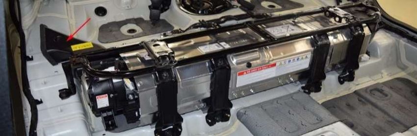
Table 35: Final test result on RDE95@35°C .......................................................................................................... 62
Table 36: Thermal management solutions ........................................................................................................... 63
Table 37: BJA test synthesis .................................................................................................................................. 68
Table 38a and b: Conditions of occurrence of "felt" derating .............................................................................. 69
Table 39: SNM tests results synthesis .................................................................................................................. 77
Table 40: Derating details of different E-Tech applications at BOL ...................................................................... 78
Table 41: Modification table SNM HEV water cooling solution............................................................................ 84
Table 42: Comparison of cooling needs and potentials BJA air cooling vas SNM water cooling .......................... 85
Table 43: Cooling systems comparative synthesis................................................................................................ 87
Table 44: Cooling systems SWOT.......................................................................................................................... 88
Table 45: HEV market analysis table..................................................................................................................... 91

 9
1. INTRODUCTION

 1.1. CONTEXT

 1.1.1. COMPANY’S PRESENTATION
 The Renault group is a French car manufacturer coming from the Renault company that was founded
in 1899 by the brothers Louis, Marcel and Fernand Renault.

This manufacturer, quickly distinguished itself by its innovations and made itself known by its participation in
motor races. The company was nationalized in the aftermath of the Second World War under the name of
"Régie Nationale des Usines Renault". The company is listed on the stock exchange since 1994 and
privatization was effective in 1996, following the sale of 6% of its capital by the French State.

The Renault group has been linked to the Japanese manufacturers Nissan since 1999 and Mitsubishi since
2017, through the Renault-Nissan-Mitsubishi alliance. This alliance has enabled brands to keep their own
identities while offering vehicles based on the same platforms, and enabled to become, in 2019, the group of
automobile manufacturers which sells the most vehicles around the world.

The Renault group is thus the first French car manufacturer in the world, thanks to the Alliance. The group
continues to renew the automotive offer and prepares for the future by responding to both the technological
and societal challenges of tomorrow: connected, autonomous vehicle, zero emissions, alternative energies,
new mobility offers. For this, the group is committed to innovative solutions for sustainable mobility, relies on
an aggressive international deployment strategy and strengthens its partnerships: Alliance with Nissan and
Mitsubishi, partnership with Daimler, cooperation with AVTOVAZ in Russia and is allied with Dongfeng in
China.

The Renault Group today brings together more than 181,000 employees in 39 countries. In 2019, it sold more
than 3.8 million vehicles in 134 countries, manufactured at its 38 industrial sites in France and abroad. The
group's activities are carried out through 5 different brands: Renault, Dacia, Lada, Renault Samsung Motors
and Alpine. Historic manufacturer of internal combustion engines and a pioneer of electric vehicles, Renault
group is launching itself nowadays in hybrid vehicles through its E-Tech innovation.

 1.1.2. CONTEXT OF THE PROJECT
 The E-Tech project is a hybrid vehicles project developed in an accelerated period by the Renault Group
with the aim of positioning itself at the level of the main hybrid competitors, and motivated by several
constraints linked to the environment. Indeed, global warming has forced European authorities to impose
increasingly strict measures in terms of CO2 emissions on car manufacturers, with the presence of financial
penalties in the event of non-compliance with the objectives set.

 Thus, the ambitious goal of seeing vehicles emit less and less CO2 with the European standard Euro 7 in
sight by 2024 pushes car manufacturers to adapt their strategy and sales volumes concerning electrified
vehicles. At the same time, there is a gradual and constrained decrease in the sales volume of diesel engines.
Indeed, the image of the diesel engine has deteriorated sharply since the "Dieselgate" affair, which created a
crisis of confidence between manufacturers and the authorities over it. In addition, the diesel engine is
criticized for its emissions of carcinogenic particles.

However, despite the rise in power of electric motorization, internal combustion engines have not yet said
their last word and are still undergoing major research projects. To face the environmental constraints
mentioned above, the most suitable solution to deal with sales reduction of diesel engines and reduction of
C02 emissions, consists in hybrid petrol engines. The great autonomy provided and the reduced consumption
of this solution aims to satisfy the old diesel drivers, while being in phase with the objectives of reducing CO2
emissions, and more particularly in city cycles.

It is therefore with this in mind that the E-Tech project is taking place, which is the very first hybrid powertrain
project of the Renault Group.

The electrical contribution in hybrid vehicles can be in very variable proportions depending on the applications
and add several functions contributing to fuel economy. There are therefore different levels of hybridization
before reaching a full-electrified vehicle. These levels depends on the amount of electrical energy used by the
system, such as described as described in table 1.

 Table 1: Different levels of electrification in vehicles [1] [2]

 Micro Mild and Soft Full hybrid Plug-in hybrid 100% electric
 hybrid hybrid HEV PHEV EV
 Electric Motor- 2-4 kW 5-20kW >20 kW >40kW >70 kW
 Generator power
 High Voltage 12V à 48V 48V à 150V 150V à 300V 300V à 600V >300V
 battery voltage
 range
 Features that help Start-stop Start-stop Start-stop Start-stop Full electric
 to save fuel function function function function driving, no fuel
 Energy Energy recovery Energy recovery Energy recovery use (except when
 recovery Electric Electric Electric using range
 assistance and assistance and assistance and extender)
 low to moderate boost Boost
 boost Restricted Extended electric
 electric driving driving

 Potential fuel
Figure 1: Components of E-Tech's powertrain

 In fact, the main innovation and particularity of the E-Tech hybrid system lies on the architecture of the
gearbox. Indeed, this innovation allows:

 - The best adaptation of the traction mode between two electric gear ratios and 4 thermal gear ratios.
 - The exploitation of a hybrid configuration mixing the possibilities of a series and/or parallel
 hybridization.
 - The best energy use between the flows of the ICE, the electric machine and the High voltage Stator
 Generator.

This system distinguished itself by the absence of clutch system. Indeed, the shifting takes place by the
different interlocking of three removable dogs clutch and offers a combination of fifteen different driving
modes. In order to ensure a good quality gear change, in terms of comfort and acoustics, the High voltage
Stator Generator allows the good synchronization of the different shafts during interconnections. The
architecture of the gearbox is described in figure 2.

 Figure 2: Architecture of E-tech dedicated hybrid gearbox

This technology thus allows fifteen different combinations of driving modes and therefore represents a
completely new hybrid technology which differs from the main hybrid technologies already available on the
HEV market such as the parallel and series hybridizations of Hyundai / Kia and Nissan respectively, or the
mixed and decoupled serie-parallel hybridizations of Toyota and Honda respectively. The properties of these
four systems as well as those of E-Tech are summarized in figure 3.

 12
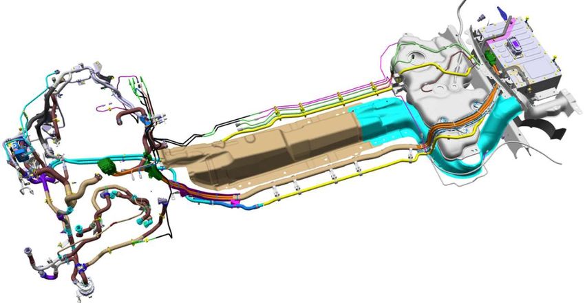
Figure 3: Overview of hybrid topologies

However, hybrid system also implies the integration of a high-voltage battery, which is an action that meets a
system need essential to the operation of a hybrid vehicle. This battery must be installed in the vehicle despite
significant mass and volume constraints, be able to supply high voltage electrical energy to electric machines,
manage this energy in order to optimize its use and be maintained at an acceptable thermal level by a
dedicated cooling system so as not to cause malfunction or fires [3].

Indeed, the HEV high-voltage battery is subjected to very high thermal stresses, stresses even higher than for
those of other applications of electrified vehicles. This is due to the fact that the batteries used in HEV are
power batteries, with a higher power/volume ratio than in the other electrified applications. The DCR (Direct
Current Resistance) of the battery cells thus causes heat losses proportional to this power on a small exchange
surface.

This cooling system thus represent a massive issue on HEVs because of its strong impact on the so called
“customer performance”. Customer performance represent all aspects of the vehicle that have a direct impact
on the customer’s user experience, and which can potentially be subject to complaints from the user. This
analysis will thus be carried out with attention paid to these customer performance. This point of view thus
aims to anticipate potential complaints that may be caused by the cooling system of the high voltage battery.

In the case of E-Tech high voltage battery cooling solution, air cooling is the first option due to the moderate
cost of the solution. In terms of customer performance, this solution will mainly impact directly or indirectly:

 - Performance : battery's overheating can imply a degradation of the electrical performance provided
 and thus a derating of the traction performance of the vehicles.
 - Driving pleasure: this same decrease in electrical performance can cause a loss of EV Feeling, which
 can be felt by users.
 - Consumption : The cooling solution can involve elements having an electrical consumption, and
 directly or indirectly impact the consumption of the air conditioning compressor.
 - Thermal reliability/durability and comfort : cells overheating can affect their integrity, and also cause
 thermal discomfort in the passenger compartment.
 - NVH : The cooling solution includes elements capable of generating noise, vibrations and harshness.

 13
However, this study also takes into account a major detail concerning the air cooling solution: GTREVS
regulation scheduled for 2021 which prohibits recirculation of air in the passenger compartment if it has been
directly in contact with battery cells during the cooling process.

The objective of this study is therefore to set up an air battery cooling system taking into account the elements
mentioned above, in order to assess the viability of this solution compared to other existing solutions, and to
identify the strengths and weaknesses for future applications.

 1.2. COMPETITION OVERVIEW ON HV BATTERY INTEGRATION AND COOLING

 1.2.1. STUDIED VEHICLES AND COMPETITORS
 The development of the of this study revolves mainly around the first pioneering project which
concerns the new Clio E-Tech, so called BJA in this study.

As BJA is only a small city-dweller, the study will then be extended in order to take into account a vehicle with
bigger aerodynamic and mass constraints, and therefore inducing bigger solicitations on the high-voltage
battery, as an opening in section 5. This vehicle is assumed to be a SUV-crossover that will be called SNM in
this study.

These two vehicles are part of the B/I2 segment, even if SNM has dimensions that approach the ones of the
C/M1 segment.

The general characteristics of these two vehicles are presented in table 2.

 Table 2: BJA and SNM vehicles characteristics

 SPECIFICATION BJA HEV SNM HEV COMMUN STRUCTURE

 Type City-dweller SUV crossover Hybrid configuration
 Year 2020 2020 Serie-Parallel
 Size 4050/1790/1440 4227/1797/1585
 GVWR 1792kg 1913 kg
 EV range 0-4 kms 0-4 kms

 System E-Tech E- Tech
 Emissions norm Euro 6 Dfull Euro6 Dfull

 82 g/km /
 NEDC Emissions

 WTLP Emissions 96 g/km / Transmission/Gearbox
 GPF Oui Oui 2 Electric gears + 4 thermic gears=
 ICE Designation 1.6L 1,6L 15 kinematics modes + 3 dog-
 Type Gasoline Gasoline clutches
 Power 67 kW 67 kW
 Torque 149 Nm 149 Nm
 EM Power 35 kW 35 kW
 Torque 212 Nm (4 sec) then 212 Nm (4 sec) then
 205 Nm 205 Nm
 Combined power 140 hp 140 hp
 Traction power sum 140 hp 140 hp
 Power completation 100% 100%

 HSG Power 15 kW 15kW Battery position
 Torque 50 Nm 50 Nm Under the trunk
 Battery Type Li-Ion Li-Ion
 Cooling system Air from the cabin + Air from the cabin +

 14
Fan No contact with Fan No contact with
 cells from the battery cells from the battery
 Capacity 1,2 kWh 1,2 kWh
 Nb of cells 68 cells 68 cells
 Cells supplier Hitachi Hitachi
 Voltage 250 V 250 V
 Output power 43 kW 43 kW
 Trunk volume 306L 372L

 Tank volume 39L 48L

Before going into the analysis of the EE-Tech
 Tech battery cooling system, it is interesting to study the high voltage
battery cooling systems present on the others HEV on the market. A series of segment B and C vehicles more mor
or less close to the two studied vehicles aree selected. These vehicles come from the four major hybrid
topologies presented in figure 3 and their choice
 choices are justified in table 3.

 Table 3: Main HEV competitors

 BJA HEV SNM HEV
Vehicles with Hyundai Ioniq HEV – Honda CR-V – Toyota Corolla
interesting
technology
Vehicles not particularly
close to E-Tech vehicles
but presenting a Paternity of HEV system Paternity of HEV system I-MMT First Li-Ion battery on Toyota HEV
technological interest BSG+1M2C DCT
specific to their hybrid
system.
Secondary Toyota Yaris 3 HEV - Nissan Note E-Power Toyota CH--R – Kia Niro HEV
competitors –
currently
Current vehicles having
the same target but not
 Released in 2012, Released in 2012, absent Restyled in 2019 in a C-SUV larger in size
presenting the most
 restyled in 2017 and from the European more upscale version than SNM, less close
recent technologies of the
 about to be renewed in market than the SNM target and recent than the
competition.
 2020 Kona

Front-end Toyota Yaris 4 HEV Hyundai Kona HEV
competitors
Near or recent outings
that come closest to the
studied vehicles in terms
of characteristics and Will be released in 2020 just like BJA, a significantly Released in 2019, the only true hybrid B-SUV
 B on
target objective. improved version of the Yaris 3, already the market the market with dimensions close to that of SNM.
 leader in hybrid city cars.

Secondary Honda Jazz I-MMT Nissan Qashqai E-Power
 E
competitors – future
Other competing vehicles
to come on which
information remains too
limited for the study.

 Also coming out in 2020, but still little information on First appearance of E--Power in Europe planned on
 this vehicle this crossover SUV for 2021

An overview of the general characteristics of these vehicles is available through the competition analysis table
detailed in the table 45 in appendix.

 15
The analysis of these competing vehicles will first focus on the high voltage battery itself and its integration,
before then looking in more detail at the different cooling systems used.

 1.2.2. COMPETITORS BATTERY AND INTEGRATION ANALYSIS
A general overview of the known characteristics of competing batteries is presented in the table 4.

 Table 4: Benchmark of competitors HEV batteries

 TOYOTA
Corolla 122ch CH-R
 R 122ch Yaris 3 Yaris 4

Cells supplier: PEVE Cells supplier: PEVE
 Cells supplier: PEVE Cells supplier: PEVE
Battery Type: Li-Ion Battery Type: Ni-Mh
 Battery Type: Ni-Mh Battery Type: Li-Ion
Pack energy: 1,3 kWh Pack energy: 1,3 1,31 kWh
 Pack energy: 0,94 kWh (50% Pack energy: 1 kWh
Number of cells: 168 (66% USOC)
 USOC) Number of cells: 48
Battery Voltage:2O7V Number of cells: 28 x 6
 Number of cells: 20 x 6 Battery Voltage: 177,6 V
Output Power: Battery Voltage:2
 Voltage:202V
 Battery Voltage:144V Output Power:
 Output Power:
 Output Power:
 KIA/HYUNDAI NISSAN HONDA
Ioniq – Niro - Kona Note E--Power CR-V Fit Jazz

Cells supplier: LG chem Cells supplier: Hitachi Cells supplier: General Motors Cells supplier: General Motors
Battery Type: Li-Ion Battery Type: Li-Ion Battery Type: Li-Ion Battery Type: Li-Ion
Pack energy: 1,56 kWh (60% Pack energy: 1,
 1,5 kWh Pack energy: 1,5 kWh Pack energy: 0,9 kWh
USOC) Number of cells: Number of cells: Number of cells:
Number of cells: 4x16 Battery Voltage
 Voltage: 310V Battery Voltage: Battery Voltage:
 Voltage
Battery Voltage:240V Output Power: 40kW Output Power: 27kW Output Power:
Output Power: 42kW

These batteries can thus be categorized into two general categories according to the type of chemistry
 chemist used.
This is summarized in table 5 which also presents the strengths and weaknesses of each chemistry.

 Table 5: Comparison Li-Ion vs NiMh [4]

 LITHIUM-ION BATTERY NICKEL METAL HYDRIDE
 IDE BATTERY
 Nissan Note E-Power X
 Hyundai/Kia Ioniq, Niro et Kona X
 Toyota Corolla 122ch, Yaris 2020 CH-R 122ch, Yaris 2012
 Honda CR-V, Jazz 2020 X
 Benefits -No
 No "memory" effect, better resistance to wear -Economic
 -Better
 Better ratio of energy quantity and power / -Less
 Less subject to overheating: the exchange surface
 volume is enlarged
 ged for a similar power
 -Less
 Less maintenance and upkeep requirements -Less
 Less security constraints related to the product
 Disadvantages - Danger of short circuit in case of contact -Lower
 Lower power / energy volume ratio
 between the electrolytes - Memory effect which reduces the lifespan during
 - Price repeated charges / discharges
 - Overheating

 16
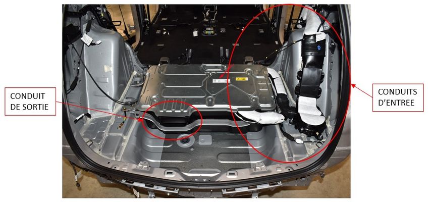
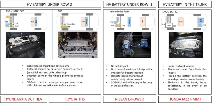
It can be seen that every HEV competitors are now using Li-Ion batteries. This increases the stress on thermal
control of the battery because this type of chemistry is more strongly subject to overheating, since the same
amount of heat is dissipated over a smaller area [5]. This highlights the importance of the battery cooling
system.
Before installing the cooling system, it is also important to take into account the placement of the high voltage
battery in the vehicle. The figure 4 presents a summary of the high voltage battery competitor's location
choices, specifying their characteristics, strengths and weaknesses in terms of security, comfort and
inhabitancy.

 Figure 4: Competitors high voltage battery's integration

However, the location of the battery also has impacts on its cooling system. These solutions have different
volumes available as well as a different distance from the passenger compartment and the fresh air
conditioning outlet. These different factors can have an influence on the installation and efficiency of air
cooling.

A row 1 location of the high voltage battery implies a short length of duct and a better proximity of the fresh
air leaving the air conditioning at the expense of a reduced implantation volume of the solution. A row 2
location offers more space but an air intake further away from the fresh air from the air conditioning. Location
under the trunk also provides additional space but involves a greater length of intake duct.

It is by knowing the subtleties linked to each type of integration that it is now possible to carry out studies of
the various HEV battery cooling systems on the market.

 1.2.3. COMPETITORS COOLING SYSTEMS ANALYSIS
 The studies of the HEV battery cooling systems on the market will focus more particularly on the most
common solutions from vehicles integrating their batteries in the rear unit of the vehicles, either at the level of
row 2 or the trunk.

 • HYUNDAI/KIA :

Like the high voltage battery, the battery cooling system of the Hyundai / Kia HEV systems is a common item to
the HEV and PHEV versions, with a second battery and a second cooling unit simply added under the trunk
floor in the latter.

 17
The air is thus sucked inside the cabin by a fan on the level of the left side of the rear seat. The air therefore
cross the battery pack and therefore performs convection cooling tran
 transversely
 sversely to the cells, making it possible
to obtain a large surface area for heat exchange. The air intake blower is located downstream of the other side
of the battery. This fan is controlled by the Battery Management System which evaluates the cooling needs.
 ne

The air is then directed into a hollow body, which helps to extract it outside without depressurizing the
passenger compartment. It is therefore judicious to be able to evacuate this hot air so as not to heat the
passenger compartment and therefore th thee air captured for cooling the battery. In addition, the short length of
the conduits makes possible to limit the pressure drops and therefore to optimize the cooling rate.

This system used in the three Hyundai / Kia vehicles in the study is summarized in table 6.
 6

 Table 6: Hyundai/Kia's HV battery cooling system

 Hyundai/Kia cooling system
 Cooling Type Air cooling
 Thermal Transfer type Direct forced convection with a fan
 System overview

 Location Under row 2

 Air inlet Beside the left rear sseat
 Air outlet Inside the hollow body at the right of row 2
 Blower's location Downstream – air sucked into the battery
 Air circulation

 Cells

 Hollow
 body

 18
Strengths • Short duct length - Small pressure drop
 • Large exchange area
 • Good distribution of air flow
 • Direct convection - Efficient cooling
 • Favored hot air extraction
 Weaknesses • Possible entry of dirt in the battery pack - Filtration required
 • Potential entry of dangerous gases into the cabin during degassing of the
 battery
 •Non compliance with GTREVS 2021

 • TOYOTA :

The cooling system used by Toyota is also an air-cooling system by direct air convection on the cells to cool the
HV battery located in row 2. The process varies slightly depending on the model:

 - For the Corolla 122ch, the air is sucked through the inlet duct located on the left of row 2. After
 passing through a long duct probably involving significant pressure drops, the air reaches the blower
 located upstream then is pushed into the battery by its inlet at the top left. Air is rejected everywhere
 near the battery by the casing which is not sealed since there are no other duct outlets.
 - For the CH-R, the air is sucked into the inlet duct by the blower located just behind the intake grille
 located to the right of row 2 then pushed into the battery by its inlet at the bottom right of the
 battery and comes out at the top right after being in contact with the cells placed vertically. This short
 CH-R outlet duct directly rejects air near the battery.
 - For the Yaris 3, the air is sucked into the inlet duct by the blower located just behind the intake grille
 located to the left of row 2, then pushed into the battery by its inlet at the bottom left from the
 battery and comes out at the top right after being in contact with the cells placed vertically. The
 outlet duct rejects the air in the hollow body to the right of row 2, which helps it to be extracted
 outside without depressurizing the passenger compartment.

Interestingly, Toyota still chooses to push air into the battery with the blower. In addition, it can be seen less
and less effort in redirecting hot air at the battery outlet over vehicles. Toyota just rejects the hot air near the
battery, and questions about the impact of hot air redirection. The cooling systems of Toyota vehicles are
summarized in table 7.

 Table 7: Toyota's cooling system

 Toyota's cooling system
 Vehicle Corolla 122ch CH-R 122ch Yaris 3
 Cooling Air cooling
 type
 Thermal Direct convection forced with a fan
 Transfer
 type
 System
 overview

 Location Under row 2

 Air inlet Under left rear seat Under right rear seat Under left rear seat
 Air outlet In the hollow body at the left of row 2

 19
You can also read