Human Hair Inverse Rendering using Multi-View Photometric data
←
→
Page content transcription
If your browser does not render page correctly, please read the page content below

Eurographics Symposium on Rendering (DL-only Track) (2021)
A. Bousseau and M. McGuire (Editors)

Human Hair Inverse Rendering using Multi-View Photometric data

 Tiancheng Sun1 , Giljoo Nam2 , Carlos Aliaga2 , Christophe Hery2 , Ravi Ramamoorthi1
 1 University of California, San Diego
 2 Facebook Reality Labs

 Abstract
 We introduce a hair inverse rendering framework to reconstruct high-fidelity 3D geometry of human hair, as well as its re-
 flectance, which can be readily used for photorealistic rendering of hair. We take multi-view photometric data as input, i.e.,
 a set of images taken from various viewpoints and different lighting conditions. Our method consists of two stages. First, we
 propose a novel solution for line-based multi-view stereo that yields accurate hair geometry from multi-view photometric data.
 Specifically, a per-pixel lightcode is proposed to efficiently solve the hair correspondence matching problem. Our new solution
 enables accurate and dense strand reconstruction from a smaller number of cameras compared to the state-of-the-art work.
 In the second stage, we estimate hair reflectance properties using multi-view photometric data. A simplified BSDF model of
 hair strands is used for realistic appearance reproduction. Based on the 3D geometry of hair strands, we fit the longitudinal
 roughness and find the single strand color. We show that our method can faithfully reproduce the appearance of human hair and
 provide realism for digital humans. We demonstrate the accuracy and efficiency of our method using photorealistic synthetic
 hair rendering data.

1. Introduction

With emerging technologies of augmented reality and virtual re-
ality, creating photorealistic digital humans is gaining increasing
attention in computer vision and graphics. Inverse rendering is a
widely used technique that can alleviate 3D artists’ labor-intensive
tasks of modeling high-fidelity digital humans. For human inverse
rendering, there have been several successful approaches to build
capture systems that produce multi-view photometric data, which
is a set of images taken from various viewpoints and under different
lighting conditions. From the images, inverse rendering framworks
are able to reconstruct detailed geometry as well as complex ma- Input Images Reconstruction / Groundtruth
terial appearance of human skin, e.g., specularity and subsurface
 Figure 1: Demonstration of our method on synthetic hair ren-
scattering. While previous research on digital humans achieved
 dering data. (Left) Some of our input images. (Right) A rendering
great success on faces and bodies, inverse rendering for high-
 of our reconstructed hair model. Our hair inverse rendering algo-
fidelity hair data is still an open problem due to the inherent charac-
 rithm can produce a full hair model with geometry and reflectance
teristics of hair, i.e., the microscale geometry and the large number
 information, which is accurate and realistic.
of hair strands. In this paper, we present a novel inverse rendering
framework to reconstruct detailed hair geometry as well as its re-
flectance, which can be readily used for photorealistic rendering of
digital humans.
 a 3D line cloud from multi-view images. Their method, how-
 Following recent successes of human inverse rendering research, ever, requires densely positioned cameras (70 cameras on a hemi-
we use multi-view photometric data. As a first stage, we reconstruct sphere) and relies on several heuristics for correspondence match-
hair geometry with strand-level accuracy. Traditional multi-view ing and view-selection. We propose a new solution for line-based
stereo techniques fail in this stage as they are designed to recon- multi-view stereo that gives us more densely reconstructed strands
struct 3D surfaces, not 3D strands. The main challenge is to find even from a smaller number of views compared to the previous
pixel-wise correspondences across views. Nam et al. [NWKS19] work [NWKS19] (Section 4). We design a new matching cost func-
proposed a line-based multi-view stereo algorithm that reconstructs tion that fully utilizes the photometric data. We introduce lightcode,

© 2021 The Author(s)
Eurographics Proceedings © 2021 The Eurographics Association.
T. Sun, G. Nam, C. Aliaga, C. Hery, R. Ramamoorthi / Human Hair Inverse Rendering using Multi-View Photometric data

a per-pixel light encoding that stores information about whether a 2.2. Image-based Hair Modeling
small hair segment can be lit by each light or not. Using the light-
 There have been many efforts to model hair geometry using cap-
code, we efficiently solve the hair correspondence problem as well
 tured images. Please refer to [BQ18] for an overview. A com-
as the per-pixel view selection problem.
 mon approach is to use a multi-view setup. Most existing methods
 Using the reconstructed hair geometry, the second stage esti- first obtain a rough geometry from structured-light [PCK*08], vi-
mates reflectance properties using photometric data (Section 5). sual hull [PBS04; WOQS05], multi-view stereo [LLP*12; LLR13;
Estimating the reflectance of hair is challenging, since the over- XWW*14; HMLL14; HML*14; HBLB17; EBGB14; BBN*12],
all appearance of hair is the result of the aggregated multiple in- depth-from-focus [JMM09], thermal video cameras [HZW12], or
teractions of light with each single hair fiber of about 80 microns an RGB-D sensor [HML*14], and run an additional strand-fitting
thickness. Each of those fibers exhibits highly anisotropic, complex step to get 3D hair strands. Recently, Nam et al. [NWKS19] pre-
light scattering patterns. To estimate the full reflectance properties sented a line-based multi-view stereo method that directly recon-
of hair strands, a highly complex and sophisticated capture sys- structs 3D hair strands from images, thus achieving high accu-
tem with a microscope is needed [KM17]. Therefore, we propose racy. Paris et al [PCK*08] showed the feasibility of a hair inverse
a practical solution to use a simple hair reflectance model and fit rendering pipeline using multi-view and multi-light images. They
the parameters using our reconstructed geometry and illumination first reconstruct 3D geometry of hair using structured light patterns
information. and estimate its reflectance using controlled illumination. Different
 from [PCK*08], we reconstruct hair strands directly from multi-
 We demonstrate our method using synthetic hair rendering data
 view photometric data using our novel solution.
(Fig. 1). We use high-quality human head models and hair strand
models that are created by digital artists and render photoreal- Hair capture from a single image is another stream of re-
istic images using Blender. To mimic a real-world capture en- search [HMLL15; HML*14; CWW*12; CWW*13; CLS*15;
vironment, we place multiple virtual cameras and light sources CSW*16; ZCW*17]. These are data-driven methods that utilize a
on a hemisphere pointing towards a subject, similar to the Light- large number of manually created 3D hair models. More recently,
Stage [GLD*19]. deep learning-based approaches were proposed. Pre-trained net-
 works, such as convolutional neural networks [ZHX*18] or gen-
 In summary, we introduce the following contributions:
 erative adversarial networks [ZZ19], were used to infer 3D hair ge-
• A hair inverse rendering framework using multi-view photomet- ometry from a single image. While these methods have the benefit
 ric data that yields high-fidelity hair geometry and its reflectance, of easy capture, the reconstructed geometries are not suitable for
 which can be used for photorealistic rendering of hair on virtual photorealistic rendering.
 characters.
• A novel solution for line-based multi-view stereo that yields ac-
 curate hair geometry from multi-view photometric data. By us- 2.3. Hair Reflectance Model
 ing lightcode, our method can reconstruct denser strands with The seminal work of Marschner et al. [MJC*03] described the com-
 sparser cameras compared to state-of-the-art work. (Section 4) plex light transport within each human hair fiber, representing it as
• Hair reflectance estimation using multi-view photometric data. a rough dielectric cylinder. This work resulted in the classification
 Given the estimated fiber direction and a set of light and cam- of different scattering modes, namely R for the primary reflectance,
 era vectors, we leverage these sparse samples of the hair BSDF TRT for a secondary colored and attenuated reflection offset from
 to estimate the multiple scattering albedo and the longitudinal the primary, and TT for a transmission term, responsible for most
 roughness that define the overall color of the hair and the width of the observed hue of the hair. D’Eon et al. [dFH*11] refined this
 of the highlights respectively. (Section 5) far field model into a more principled spherical Gaussian for the
 longitudinal (along the fiber) component, and supplied a separate
 roughness control on the azimuthal (in the cross sectional plane of
2. Related Work
 the cylinder) term. More recently, Chiang et al. [CBTB15] returned
2.1. Multi-view Photometric Stereo to a near field solution, and provided a fourth TRRT lobe to cover
 the missing energy from the additional internal bounces not consid-
Multi-view stereo [HZ03] has been widely used to reconstruct
 ered previously. We start from a base implementation of this model
3D geometry from images taken from multiple viewpoints un-
 in Blender [Ble20] and add explicit artistic and debugging factors
der a fixed lighting condition. On the other hand, photometric
 for each term, also improving the convergence via fits similar to the
stereo [Woo80] reconstructs surface normals, as well as surface re-
 approaches from Pekelis et al. [PHVL15].
flectance, using multiple images taken from a fixed viewpoint but
under varying illumination. Multi-view photometric stereo com- Previous work has tried to match the appearance of hair from a
bines the two techniques to get rich information of 3D geome- single image [BPV*09], but accuracy is limited because they do not
try and surafce reflectance at the same time [SDR*20; LMC19; utilize accurate strand level hair geometry. Zinke et al. [ZRL*09]
PSM*16; ZWT13; YY11; HVC08; TFG*13; DYW05; KN08]. proposed to measure the reflectance properties of hair fibers coiled
The multi-view and multi-illumination setup has proven to be ef- around a cylinder. Progress has also been made in the case of tex-
fective for creating photorealistic digital humans. However, most tile fibers [KSZ*16] based on volumetric representations of fiber
work has focused on faces [FJA*14; FGT*16; GFT*11] and bod- assemblies. Different from previous work, we rely on explicit fiber
ies [ZFT*20; VPB*09; GLD*19], and is thus not applicable to hair. level estimation of hair geometry and do not depend on the usual

 © 2021 The Author(s)
 Eurographics Proceedings © 2021 The Eurographics Association.

T. Sun, G. Nam, C. Aliaga, C. Hery, R. Ramamoorthi / Human Hair Inverse Rendering using Multi-View Photometric data

limitations of traditional hair reflectance models, being able to 4.1. 2D Orientation Map
model any kind of color coming from dyes, or extra coating or wet-
 4.1.1. Per Light Orientation Extraction
ness layers.
 Similar to previous work [PBS04], we filter each photometric im-
 age Ic (l, x, y) under a point light l and camera c with a set of con-
3. Overview volutional kernels, and find the per pixel 2D orientation from the
 maximum response. We use log-gabor filters [FŠP*07] rather than
An overview of our hair inverse rendering pipeline is shown in gabor filters, because they have finer frequency supports:
Fig. 2. The input of our framework is multi-view photometric data,
i.e., a set of images taken from various view-points and different Rθ (l, x, y) = σθ ∗ Ic (l, x, y)
lighting conditions. We assume that Nc cameras are pointing to- Θc (l, x, y) = argmax Rθ (l, x, y)
wards the subject and there are Nl point light sources (Nl ≥ Nc ). θ (1)
We also assume that each camera has a co-located light source. ∑ R (l, x, y) · cos(θ − Θc (l, x, y))
 Wc (l, x, y) = θ θ ,
Given Nc × (Nl + 1) images captured from all cameras under each maxθ Rθ (l, x, y)
light source (and additional uniform lighting), we first reconstruct where Rθ (l, x, y) is the convolutional response at pixel (x, y) with a
a dense set of hair strands using the theory of multi-view photomet- θ-rotated log-Gabor filter σθ . Θc (l, x, y) and Wc (l, x, y) are the 2D
ric stereo (Section 4), and then estimate the reflectance properties orientation map and the confidence map for image Ic (l, x, y).
of the hair strands using the inferred geometry (Section 5).
 We develop our algorithm based on synthetically “captured” 4.1.2. Per View Orientation Merge
data. We use high-quality human head models and hair strand mod-
 After we extract the 2D orientation and its confidence from each
els created by digital artists, and use Blender to render the input
 photometric image under a specific camera c, we apply a weighted
images. Specifically, we place Nc = 24 cameras on the upper hemi-
 average on the per light 2D orientation and confidence:
sphere, aiming at the hair region, and then distribute Nl = 36 point
lights uniformly on the sphere. We make sure that each camera has Θc (x, y) = ∑ Wc (l, x, y) · Θc (l, x, y)
a co-located point light source. Using synthetic data has the fol- l
 (2)
lowing advantages. First, we have access to the ground-truth hair Wc (x, y) = ∑ Wc (l, x, y) · cos(Θc (l, x, y) − Θc (x, y)),
strands which is impossible to obtain in real captured data. Second, l
we can efficiently control the dataset. For example, we can easily where the output is per-view 2D orientation map Θc (x, y) and con-
change the hair reflectance parameters, the number of cameras and fidence map Wc (x, y). Please refer to the supplemental material for
lights, exposure settings, etc. We render the images using the de- more details about the effect of the log-Gabor filter compared to the
fault setting of the Blender Cycles renderer [Ble20], which uses original Gabor filter.
path tracing with 1024 samples per pixel. All the images are ren-
dered with the resolution 2048 × 2048, where a single hair strand
 4.1.3. Hair Region Masking
is roughly 3 pixels wide.
 We also use a pre-trained deep neural network [YWP*18;
 LLWL20] to extract the hair region from the uniformly-lit images.
4. Hair Geometry Reconstruction We compute 2D orientation maps only for the valid hair region,
 which has great benefits in fast computation and efficient outlier
Our geometry reconstruction algorithm is inspired by the recent removal.
success of Nam et al. [NWKS19]. They proposed the line-based
multi-view stereo (LMVS) to reconstruct strand-accurate hair ge-
ometry using multi-view captures. However, due to multiple scat- 4.2. 3D Line Reconstruction
tering effects inside the hair, strands cannot be easily distinguished
 4.2.1. Lightcode
from captured images. As a result, a large number of cameras (70
views in [NWKS19]) are needed for satisfactory output, and only In multi-view stereo (MVS), finding correct correspondences
the outer surface of the hair is recovered. across views is crucial for accurate geometry reconstruction. Tra-
 ditional methods fail in hair because first, the intensities between
 We therefore use a multi-view photometric stereo (MVPS) setup neighboring pixels are highly similar, and second, due to the micro-
to solve the problem and propose a new solution for LMVS that structures of hair strands, the pixel values change rapidly with dif-
fully exploits the photometric data. In particular, we introduce ferent viewpoints. 2D orientation maps Θ(x, y) can be used for cor-
lightcode, a novel per-pixel light encoding structure. lightcode en- respondence matching [NWKS19], but it is inefficient as it involves
ables efficient neighbor view selection for multi-view stereo, and multiple projections between cameras.
also provides a strong signal for robust correspondence matching
across views. The remainder of this section describes our new so- We therefore propose to use lightcode Lc (x, y) as a matching
lution for LMVS using MVPS data. We kindly refer readers to feature to find correspondences between multiple views:
[NWKS19] for more details about basic LMVS and to [CLK09;
 Lc (x, y) = b1 b2 · · · bNl , (3)
BS05; BFV05] for more traditional computer vision approaches
that use lines. where bi is a binary bit which represents the visibility of the

© 2021 The Author(s)
Eurographics Proceedings © 2021 The Eurographics Association.
T. Sun, G. Nam, C. Aliaga, C. Hery, R. Ramamoorthi / Human Hair Inverse Rendering using Multi-View Photometric data Hair Geometry Reconstruction Hair Reflectance Reconstruction Multi-view Strand 2D Orientation 3D Line Segment Hair Roughness Hair Color Rendered Photometric Generation and Extraction Reconstruction Estimation Estimation Images Images Extension Sec. 4.1 Sec. 4.2 Sec. 4.3 Sec. 5.1 Sec. 5.2 Figure 2: An overview of our hair inverse rendering pipeline. unlit area sponding pixels in the neighboring cameras efficiently and accu- rately. In practice, we use the median pixel value of the image under the furthest light as the shadow threshold of the camera. 4.2.2. View Selection using Lightcode In MVS, neighboring view selection also affects efficiency and ac- light A light B curacy of the algorithm. Due to the lack of visibility information, traditional MVS algorithms, including [NWKS19], have to search for matching pixels in all the neighboring views. Using lightcode, we can extract the visibility information since a point light is placed cam A cam B right next to each camera. As shown in Fig 3, if one pixel of camera Figure 3: This figure illustrates how lightcode can be used for view A under light B is bright, then it means that specific pixel can also selection. We use the interchangeability of the camera rays and be observed by camera B, and vice versa. Here, we use the inter- light rays. If one pixel of camera A under light B is bright, it means changeability of the camera rays and light rays. The shadow casted that pixel can also be observed by camera B (blue point). If another by the light next to a camera represents the visibility information pixel of camera A under light B is dark, it indicates that camera B when observed from other views. We use this visibility information cannot see the pixel (red point). to select per-pixel valid neighboring views. For the remaining parts of this section, ’neighbor view’ always refers to ’per-pixel valid neighbor view’. Essentially, the lightcode encodes the visibility information at each 3D point. Since the human head is roughly a sphere, about half of the bits in each lightcode are 0. This means that for each point associated with a lightcode, a large number of cameras cannot see this point. In order to prune these invalid observations, we only use the nearest 16 cameras when we are doing 3D reconstruction. 4.2.3. Analytic Derivation of 3D Line Segment from Pixel Depth Given the 2D information (orientation map Θ(x, y), confidence neighboring neighboring W(x, y), and lightcode L(x, y)) of all cameras, our goal is to find view view the per-pixel optimal line segment S in the 3D space, represented by a 3D position S pos and a 3D line direction Sdir . We observe that reference view both S pos and Sdir can be analytically derived when the depth d of the pixel is given. For a single pixel (x, y) in camera c, assuming Figure 4: An illustration of how we analytically derive the 3D line we know its depth d, we can find the 3D location of its correspond- segment S from a given depth d. For a pixel in the reference view, ing segment S pos and project it to its visible neighbors. For each we first get S pos (the position of S) by shooting a ray toward the n-th neighboring camera, if the 3D line direction Sdir is consistent pixel. Then we get Sdir (the 3D direction of S) using Eq. 4. with the 2D line direction Θn (x pro j , y pro j ), the 3D line should lie in the plane formed by the projection ray and the 2D line on the image plane. In other words, we will get the 3D line direction Sdir by solving the equation below: pixel under light i. The lightcode shares a similar idea as Space- Ray0 (x pro j , y pro j ) × Θ0 (x pro j , y pro j ) time Stereo [DRR03], where they use pixel values from different time slices for matching between cameras. Here, we assume that .. · Sdir = 0, (4) . whether a strand is bright or not is independent of camera views, RayNn (x pro j , y pro j ) × ΘNn (x pro j , y pro j ) though its intensity is view-dependent. We use the percentage of matching bits between the lightcodes to evaluate the similarity be- where Nn is the number of neighbor views and n = 0 indicates the tween cameras. We found that the lightcode could find the corre- reference view. Here, we use Θn to represent the 2D line vector on © 2021 The Author(s) Eurographics Proceedings © 2021 The Eurographics Association.

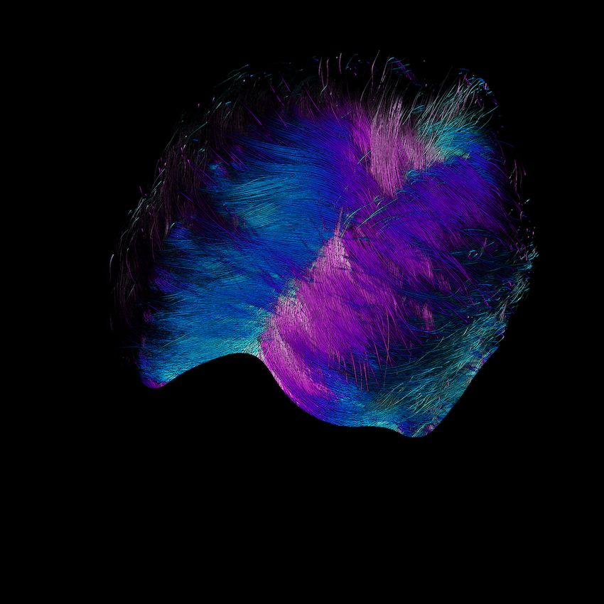
T. Sun, G. Nam, C. Aliaga, C. Hery, R. Ramamoorthi / Human Hair Inverse Rendering using Multi-View Photometric data

the image plane of the n-th neighboring camera. The equation can the following two advantages. First, during optimization, we are
be efficiently solved for Sdir by finding the singular vector corre- not only finding the best matching pixels, but also maximizing the
sponding to the smallest singular value. Figure 4 illustrates this pro- number of pixels that correspond to a strand (large W value). Sec-
cedure. In this way, we reduce the whole problem to a 1D searching ond, by formulating the problem as maximization, we implicitly set
problem w.r.t. the pixel depth d. the value of “bad matching” and “non-valid matching” to be zero,
 which leads to more stable optimization.
4.2.4. Objective Function
Now, the problem is reduced to a 1D search over the depth d for 4.3. Strand Generation and Extension
each pixel. To formulate our objective function, we sample Ns = 25
 After we generate the line segments from each pixel in each cam-
points along the 3D direction Sdir of the segment S. The sampled
 era, we follow the approach of [NWKS19] to connect them into
points are represented by the superscript s. Our objective function
 strands. We first select the small line segments S that are consistent
is a multiplication of two sub functions, the lightcode correlation
 in at least 3 neighboring cameras, and then apply the mean shift
term Olightcode and the geometric correlation term OΘ :
 algorithm on the line cloud. The mean shift algorithm efficiently
 Olightcode = mL (Lc (x, y), Ln (xspro j , yspro j )), collects the small line segments into a long strand in the 3D space.
 s
 OΘ = cos(diff(Θn (Sdir ), Θn (xspro j , yspro j ))) (5) After that, we cluster the neighboring line segments into strands.

 ·Wn (xspro j , yspro j ), At the current stage, we arrive at a set of hair strands. However,
 the connected strands do not represent the hair geometry very well.
where s indicates the sampled 3D points, n refers to n-th view, mL () The average strand length is usually under 1 cm. Thus, we further
evaluates the similarity between two lightcodes, (x, y) is the tar- extend each hair strand from its tips to get longer and more rea-
get pixel in the reference view, (xspro j , yspro j ) is the pixel coordinate sonable hair strands. For each tip P, we project the 3D point XP
where the sample s is projected to the n-th view, diff returns the 2D back to each camera, and select the cameras where the projected
angle difference, and Θn (Sdir ) is the 2D line direction of the 3D 3D direction of P aligns with the 2D direction at the projected point
line segment when projected to the n-th view. Θi (x pro j , y pro j ) (angle different less that 5◦ ). Using the aligned 2D
 Finally, we find optimal depth d per pixel, which maximizes the directions from valid cameras, we can compute the possible grow-
following objective: ing direction Sdir by following Eq. 4. After we solve for the cor-
 rect growing direction Sdir , we extend the strand for a certain step
 Ns Nn
 O= XP = XP + Sdir · dstep , where dstep = 0.05cm. We repeat this process
 ∑ ∑ Olightcode · OΘ , (6)
 until the new tip point can find no more than 5 cameras that align
 s=1 n=0
where Ns is the number of samples, and Nn is the number of neigh- with our 3D direction Sdir .
bor views. Note that n = 0 indicates the reference view. This ob-
jective function represents the overall correlation across views. We 5. Hair Reflectance Estimation
find depth d that maximizes the correlation.
 Hair reflectance is difficult to estimate due to the aggregated nature
 of hair appearance. Light may bounce many times inside the hair
4.2.5. Optimization
 volume, especially in the case of blonde or other kinds of lightly
Optimizing Eq. 6 is straightforward. For each pixel on the refer- colored hair. In order to match the look of the captured image, we
ence view, we enumerate possible depth candidates and calculate need to accurately estimate the reflectance properties of the sin-
O using Eq. 4 and Eq. 5. Then we select the depth d that returns gle fiber. There are two properties that affect the visual appearance
maximum O. This brute force search guarantees to find the global the most: the longitudinal roughness of the hair and the absorp-
optimum, but it can be slow. We therefore run a two-stage optimiza- tion coefficient. The longitudinal roughness βl controls the size of
tion. First, for each depth candidate, we only evaluate Olightcode in the highlight on the hair strands, and the absorption coefficient σ
Eq. 6 and collect the depth candidates that produce high lightcode determines how much light is absorbed by each single fiber, thus
matching. Then we evaluate the full objective O only for the se- controlling the color of the hair strands.
lected candidates. We find that this two-stage optimization enables
faster correspondence matching while preserving the output qual-
 5.1. Hair roughness estimation
ity.
 The longitudinal roughness is one of the parameters of the hair re-
4.2.6. Comparison to the Previous Work flectance model, which is usually expressed as a BSDF function.
 We use the BSDF model of Chiang et al. [CBTB15] in our paper.
Previous work by Nam et al. [NWKS19] treats the optimization as
 The general form of the BSDF model can be written as:
a multi-dimensional problem, as both the depth d and the 3D line
direction Sdir are unknown. In contrast, we treat it as a 1D problem ρ(θi , θr , φi , φr ) = ρl (θi , θr , βl ) · ρa (θi , θr , φi , φr , βa ), (7)
with a single unknown variable d. This makes our algorithm faster
 where ρl is the longitudinal component and ρa is the azimuthal
and more stable compared to [NWKS19].
 component. The meanings of angles are shown in Fig. 5. Longitu-
 Another key difference between our objective function and the dinal roughness βl determines the width of white (R) and all the
one from Nam et al. [NWKS19] is that we are solving a max- subsequent colored lobes (TT, TRT, TRRT). In contrast, the az-
imization problem rather than a minimization problem. This has imuthal roughness βa affects the overall translucency of the hair

© 2021 The Author(s)
Eurographics Proceedings © 2021 The Eurographics Association.

T. Sun, G. Nam, C. Aliaga, C. Hery, R. Ramamoorthi / Human Hair Inverse Rendering using Multi-View Photometric data

 0.200 Analytical
 ∅ Measured
 0.175

 0.150

 BSDFΔvalue
 0.125

 0.100
 ∅
 0.075

 0.050
Figure 5: Parametrization of the hair BSDF. θi and θr are the lon-
 0.025
gitudinal angles, and φi and φr are the azimuthal angles.
 0 10 20 30 40 50 60
 Δθ

 Figure 6: The measured and the corresponding fitted analytical
volume. In order to keep the problem tractable, we decide to only BSDF of the longitudinal components. Our measured BSDF fol-
optimize the longitudinal roughness βl since it is ultimately what lows the analytical BSDF when ∆θ is small, and becomes flat when
controls the most prominent visual features of hair: the length of the ∆θ is large, due to multiple scattering in the hair strands.
highlights on the strands. For this, we fix the azimuthal roughness
βa to common plausible values for human hair βa = 0.2 [MJC*03;
 Algorithm 1: Hair Color Optimization
YY97; Bhu08], and assume that the azimuthal component ρa is a
constant. The analytical BSDF function of the longitudinal compo- Function HairColorOpt(Captured Hair Image I under
nent is expressed as: uniform lighting, IterNum=5):
 Rrgb ← Ave color of the hair region in I;
 exp (−S − 1/βl ) · I 0
 ρl (θi , θr , βl ) = Crgb ← Rrgb ;
 βl · (1 − exp(−2/βl ))
 (8) for s = 0 · · · IterNum − 1 do
 where I =I0 (cos(θi ) · cos(θr )/βl )
 Rendering the hair image I (s) using hair color
 S = sin(θi ) · sin(θr )/βl (s)
 parameter Crgb ;
I0 is the modified Bessel function of the first kind, order 0. (s)
 Rrgb ← Ave color of the hair region in I (s) ;
 In order to fit to the BSDF model and solve for the longitudinal if s == 0 then
roughness, we collect the BSDF samples of the hair reflectance by (s+1) Rrgb (s)
 Crgb ← (s) ·Crgb ;
collecting the pixel values whose viewing and lighting directions Rrgb
are close to the mirror reflection: else
 (s) (s)
 π Perform linear fitting Rrgb = a ·Crgb + b
 ∆θ = |θi − θr | < ,
 6 (9)
 (s) (s)
 using Rrgb and Crgb from 0 to s;
 π
 ∆φ = |φi − φr | < . (s+1) Rrgb −b
 6 Crgb ← a ;
We divide the range of ∆θ ∈ [0, π6 ] into 32 bins, and average (IterNum)
the BSDF samples in each bin. Suppose the measured BSDF is return Crgb ;
ρm (∆θ), we find the longitudinal roughness of the hair strands by
solving the following optimization:
 ∑∆θ ρm (∆θ) · ρl (∆θ, βl )
 max q . (10) of the single fibers, but also on the azimuthal roughness βa , that de-
 βl
 ∑∆θ ρ2l (∆θ, βl ) termines the translucency of the hair volume. However, the multi-
 ple scattering albedo is invariant to hair density[CBTB15; ZW07],
 Figure 6 shows a measured BSDF and the fitted analytical BSDF given a dense enough volume of strands. Chiang et al. [CBTB15]
of the longitudinal components. The shape of the measured BSDF empirically linked the multiple scattering hair albedo Crgb to the
follows the analytical one when ∆θ is small, as the BSDF is domi- single fiber absorption coefficient σ and the azimuthal roughness
nated by the direct reflection (R component). As ∆θ becomes larger, βa using the following formula:
the measured BSDF becomes flat, due to the multiple scattering
between hair strands. For this reason, we only do our fitting on σ =(logCrgb /(5.969 − 0.215βa + 2.532β2a
∆θ ∈ [0, π6 ]. (11)
 − 10.73β3a + 5.574β4a + 0.245β5a ))2 .
 This equation gives us a good approximation of the absorption co-
5.2. Hair color optimization
 efficient σ given a fixed azimuthal roughness βa and an RGB hair
The overall perceived color of the hair, often called multiple scatter- color Crgb . This enables us to optimize for an RGB hair color Crgb
ing albedo, not only depends on the absorption coefficient σ of each instead of the absorption coefficient σ.

 © 2021 The Author(s)
 Eurographics Proceedings © 2021 The Eurographics Association.
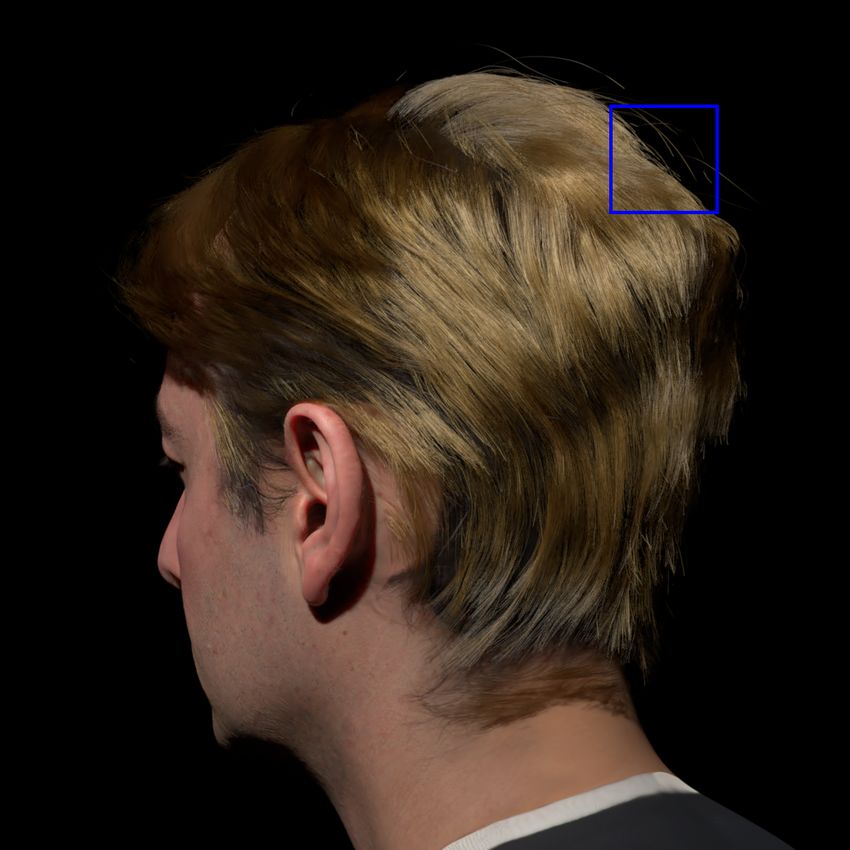
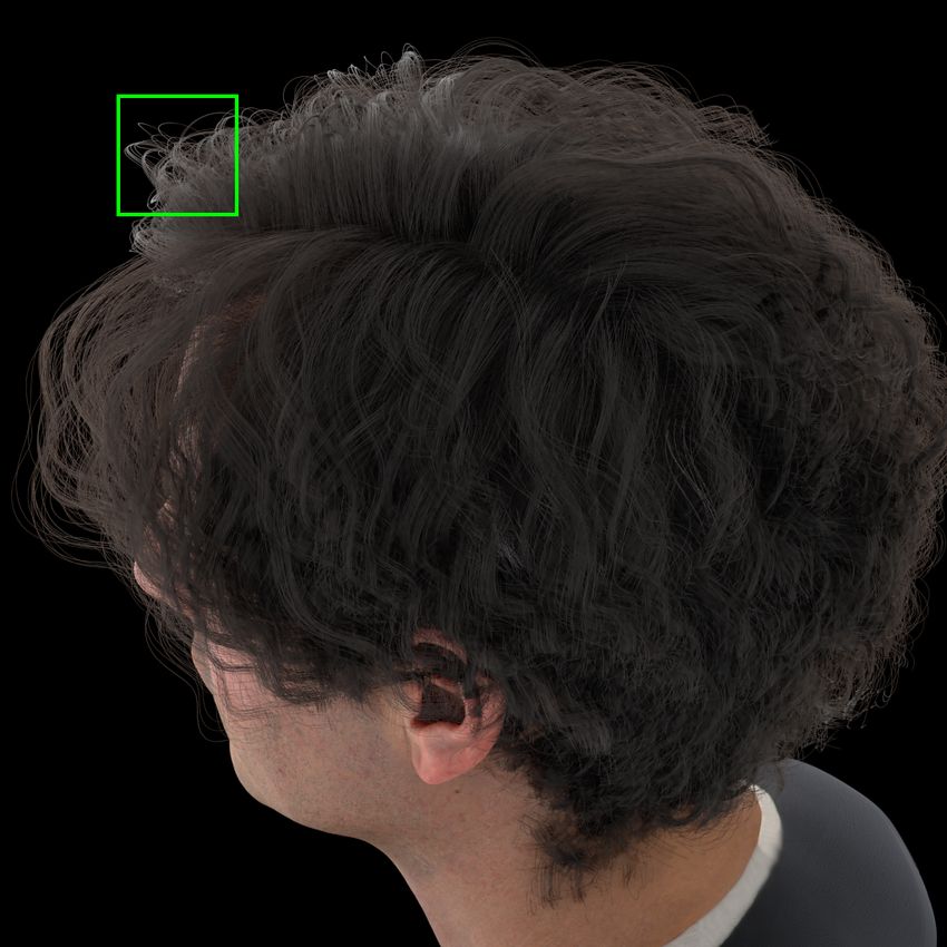
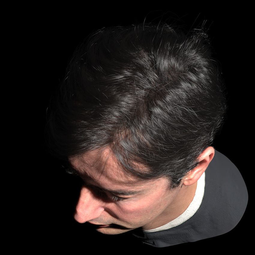
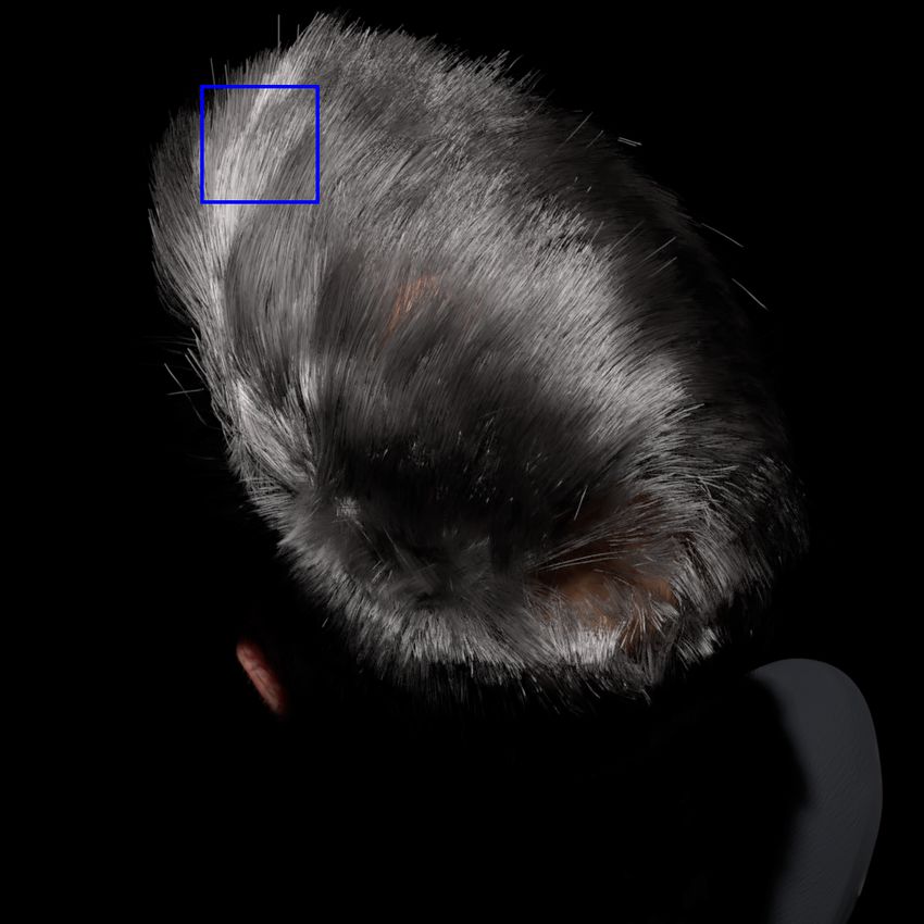
T. Sun, G. Nam, C. Aliaga, C. Hery, R. Ramamoorthi / Human Hair Inverse Rendering using Multi-View Photometric data

 We develop an iterative algorithm to find the color Crgb that Input Ours [NWKS19]
makes the color of the rendered hair match the color of the captured
hair images. We present the pseudo code of our hair color opti-
mization in Algo. 1. Given the captured hair image I under uniform
lighting, we first extract the average color Rrgb of its hair region,
 0
and initialize the color parameter Crgb as Rrgb . Then, we compute
 0
the absorption coefficient using the color parameter Crgb , render
the image of the hair I (0) , and compute the average color of the hair
region R0rgb on the rendered image. We iteratively update the color
 (s)
parameter Crgb in order to close the gap between the rendered hair
 (s)
color Rrgb and the groundtruth hair color Rrgb .

 We assume a simple linear model on the relation between the
 (s) (s)
color of the rendered hair Rrgb and the hair color parameter Crgb : Figure 7: Compared to Nam et al. [NWKS19] which uses Nc = 70
 cameras in the original paper, our algorithm better reconstructs the
 (s) (s)
 Rrgb = a ·Crgb + b, (12) hair geometry under sparse camera setups (Nc = 24).

 (s)
where s is the iteration step number, and Rrgb is the hair color of
the rendered image. This assumption is based on the observation 6.2. Results
that the pixel colors of the hair region consist of the constant color
 We now show our full results of hair inverse rendering. Given a set
part that does not change with the hair color parameter (mainly the
 of photometric hair images, we run our algorithm to get the geom-
scalp color), and the global hair albedo that is mostly linear in the
 (s) (s) etry of hair strands, the hair roughness parameter βl , and the hair
color parameter Crgb thanks to Eq. 11. As we observe more Rrgb and color Crgb . We then render the hair overlaid on a predefined hu-
 (s)
Crgb pairs, we can perform fitting based on Equ. 12, and solve the man head model using the reconstructed geometry and reflectance
optimal Crgb using the groundtruth hair color Rrgb . Our algorithm information. Rendering results of various hairstyles under uniform
can find the correct color parameter within 3 ∼ 5 iterations. light and point lights are shown in Fig. 10. Our algorithm can han-
 dle different hair styles, and the re-rendered results match with the
 groundtruth on hair color, highlight shape, as well as the overall
 hair styles.
6. Evaluation

6.1. Previous Work Comparison 6.2.1. Hair Roughness

We compare our algorithm with the current state-of-the-art work on We run our algorithm on a set of hair examples which only differ
hair geometry reconstruction [NWKS19]. [NWKS19] can recon- in their longitudinal roughness, and the reconstructed results are
struct strand-level accurate geometry of the hair given a dense set shown in Fig. 8. As we decrease the roughness, it becomes harder
of cameras (Nc = 70), while our algorithm is designed to use addi- to reconstruct the hair geometry since the highlights on the hair
tional lighting for recovering both the geometry and the reflectance strands becomes sharper and shorter (bottom-left corner). However,
from a sparse set of cameras (Nc = 24). We run both of the algo- in all three cases, our algorithm could estimate the longitudinal
rithms on our synthetic dataset, and we use the uniformly lit images roughness of the hair strands fairly well, and the highlight shape
from our cameras (Nc = 24) as the input to [NWKS19]. Figure 7 of the reconstruction matches the groundtruth image in its overall
shows visual comparison of the reconstructed strands. Our algo- appearance.
rithm can reconstruct denser and more complete hair strands com-
pared to [NWKS19]. This is because [NWKS19] relies on a large 6.2.2. Hair Color
number of camera views to eliminate outliers (non-visible camera),
 We additionally test our hair color optimization component by re-
while our algorithm utilizes the cues from lightings to select valid
 construction of hair with different colors. As shown in Fig. 9, our
camera candidates for 3D reconstruction.
 algorithm could reconstruct the fine geometry of the hair consis-
 Table 1 shows a quantitative comparison on geometry recon- tently well, regardless of the hair color. Moreover, our algorithm
struction errors following the metric in [NWKS19]. Precision could accurately recover the original hair color well.
(a.k.a. accuracy) and recall (a.k.a. completeness) values are com-
puted using the groundtruth hair geometry. τ p and τd are thresholds
 6.3. Runtime
for estimated position and direction of 3D points. We validate 3D
points if they satisfy both τ p and τd . F-score is defined as harmonic Our algorithm is implemented in Python and CUDA, and the exper-
mean of precision and recall. As shown in Table 1, our method can iments are all tested using a single NVIDIA Quadro P6000 GPU. It
reconstruct hair strands more accurately and completely compared takes around 30 minutes to apply our inverse rendering algorithm
to the previous work. on a set of synthetic hair images. For hair geometry reconstruction,

© 2021 The Author(s)
Eurographics Proceedings © 2021 The Eurographics Association.
T. Sun, G. Nam, C. Aliaga, C. Hery, R. Ramamoorthi / Human Hair Inverse Rendering using Multi-View Photometric data

 Short hair Long hair
 τ p /τd 1mm / 10◦ 2mm / 20◦ 3mm / 30◦ 1mm / 10◦ 2mm / 20◦ 3mm / 30◦
 Method Nam’19 Ours Nam’19 Ours Nam’19 Ours Nam’19 Ours Nam’19 Ours Nam’19 Ours
 Precision 46.36 42.33 78.80 86.60 85.71 96.19 33.42 32.36 69.88 75.70 85.85 88.56
 Recall 3.53 15.25 12.07 44.99 23.86 67.52 3.83 25.03 9.48 57.75 16.69 73.96
 F-score 6.56 22.42 20.94 59.22 37.32 79.35 6.87 28.22 16.70 65.52 27.95 80.60
Table 1: Precision and recall of the two datasets in Figure 7 with various threshold values. Our method outperforms the previous
work [NWKS19] in most threshold values.

 βl = 0.1 βl = 0.2 βl = 0.4 2D orientation extraction takes 700 seconds (30 seconds per cam-
 era), 3D segment generation needs 340 seconds, and strand gen-
 Groundtruth

 eration and extension takes 150 seconds. For hair reflectance esti-
 mation, it takes 300 seconds to estimate the roughness, and around
 800 seconds for hair color estimation.

 7. Conclusions and Future Work
 pred pred pred In conclusion, we have proposed a full pipeline for hair inverse
 βl = 0.10 βl = 0.18 βl = 0.35
 rendering given a set of photometric images captured from mul-
 Reconstruction

 tiple cameras. This is to our knowledge the first algorithm that
 both reconstructs the hair geometry and the fine-details of hair re-
 flectance information from only images. We demonstrated that our
 algorithm can reconstruct the hair geometry better compared to pre-
 vious works under a sparse camera setup, and also recover the hair
 reflectance properties from only a sparse set of input images.
Figure 8: Our inverse rendering results on hair with different lon- Our hair inverse rendering algorithm is not free from limitations.
gitudinal roughness values. As shown in Fig. 7 and 10, our algorithm yields sub-optimal output
 for the hair that is curly or long. In addition, as shown in Fig. 9, we
 tend to underestimate the roughness value when hair strands have
 Groundtruth Reconstruction Crop
 saturated color. Another limitation is that we can only reconstruct
 the outer hair strands that are visible from multiple cameras. A pos-
 sible future work is to estimate the 3D flow field of the inner region
 based on priors, and grow the inner hair strands to make the hair
 Brown

 style more complete. For reflectance recovery, we only estimate
 the longitudinal roughness and assume that the azimuthal rough-
 ness is constant. A direct next step is to recover the full roughness
 parameters using densely captured images.

 Acknowledgement
 This work was supported in part by NSF Chase-CI grant 1730158,
 Red

 ONR DURIP grant N000141912293, a Facebook Distinguished
 Faculty Award, A Google PhD Fellowship, the Ronald L. Graham
 Chair, and the UC San Diego Center for Visual Computing. Thanks
 to the reviewers for the valuable feedback, to Akira Orikasa and
 Cyrus Jam for the help on hair modeling, to Olivier Maury for the
 fruitful discussion, to Ronald Mallet for being the captured subject,
Figure 9: Our inverse rendering results on hair with different col- and to Tomas Simon for the help on data capture.
ors.

 References
 [BBN*12] B EELER, T HABO, B ICKEL, B ERND, N ORIS, G IOACCHINO, et
 al. “Coupled 3D reconstruction of sparse facial hair and skin”. ACM
 Transactions on Graphics (ToG) 31.4 (2012), 117 2.
 [BFV05] BAY, H ERBERT, F ERRARIS, V ITTORIO, and VAN G OOL, L UC.
 “Wide-baseline stereo matching with line segments”. Computer Vision
 and Pattern Recognition, 2005. CVPR 2005. IEEE Computer Society
 Conference on. Vol. 1. IEEE. 2005, 329–336 3.

 © 2021 The Author(s)
 Eurographics Proceedings © 2021 The Eurographics Association.

T. Sun, G. Nam, C. Aliaga, C. Hery, R. Ramamoorthi / Human Hair Inverse Rendering using Multi-View Photometric data

 Groundtruth Reconstruction Crop [Bhu08] B HUSHAN, B HARAT. “Nanoscale characterization of human hair
 and hair conditioners”. Progress in Materials Science 53.4 (2008), 585–
 710 6.
 [Ble20] B LENDER O NLINE C OMMUNITY. Blender - a 3D modelling and
 rendering package. Blender Foundation. Blender Institute, Amsterdam,
 2020. URL: http://www.blender.org 2, 3.
 [BPV*09] B ONNEEL, N ICOLAS, PARIS, S YLVAIN, VAN D E PANNE,
 M ICHIEL, et al. “Single photo estimation of hair appearance”. Computer
 Graphics Forum. Vol. 28. 4. Wiley Online Library. 2009, 1171–1180 2.
 [BQ18] BAO, YONGTANG and Q I, Y UE. “A survey of image-based tech-
 niques for hair modeling”. IEEE Access 6 (2018), 18670–18684 2.
 [BS05] BARTOLI, A DRIEN and S TURM, P ETER. “Structure-from-motion
 using lines: Representation, triangulation, and bundle adjustment”. Com-
 puter vision and image understanding 100.3 (2005), 416–441 3.
 [CBTB15] C HIANG, M ATT J EN -Y UAN, B ITTERLI, B ENEDIKT, TAPPAN,
 C HUCK, and B URLEY, B RENT. “A Practical and Controllable Hair and
 Fur Model for Production Path Tracing”. ACM SIGGRAPH 2015 Talks.
 SIGGRAPH ’15. Los Angeles, California: ACM, 2015, 23:1–23:1. ISBN:
 978-1-4503-3636-9. DOI: 10 . 1145 / 2775280 . 2792559. URL:
 http://doi.acm.org/10.1145/2775280.2792559 2, 5,
 6.
 [CLK09] C HANDRAKER, M ANMOHAN, L IM, J ONGWOO, and K RIEG -
 MAN , DAVID . “Moving in stereo: Efficient structure and motion using
 lines”. 2009 IEEE 12th International Conference on Computer Vision.
 IEEE. 2009, 1741–1748 3.
 [CLS*15] C HAI, M ENGLEI, L UO, L INJIE, S UNKAVALLI, K ALYAN, et al.
 “High-quality hair modeling from a single portrait photo”. ACM Trans-
 actions on Graphics (TOG) 34.6 (2015), 204 2.
 [CSW*16] C HAI, M ENGLEI, S HAO, T IANJIA, W U, H ONGZHI, et al. “Au-
 toHair: fully automatic hair modeling from a single image”. ACM Trans-
 actions on Graphics 35.4 (2016) 2.
 [CWW*12] C HAI, M ENGLEI, WANG, LVDI, W ENG, YANLIN, et al.
 “Single-view hair modeling for portrait manipulation”. ACM Transac-
 tions on Graphics (TOG) 31.4 (2012), 116 2.
 [CWW*13] C HAI, M ENGLEI, WANG, LVDI, W ENG, YANLIN, et al. “Dy-
 namic hair manipulation in images and videos”. ACM Transactions on
 Graphics (TOG) 32.4 (2013), 75 2.
 [dFH*11] D ’E ON, E UGENE, F RANCOIS, G UILLAUME, H ILL, M ARTIN, et
 al. “An Energy-Conserving Hair Reflectance Model”. Computer Graph-
 ics Forum. Vol. 30. Wiley Online Library. 2011, 1181–1187 2.
 [DRR03] DAVIS, JAMES, R AMAMOORTHI, R AVI, and RUSINKIEWICZ,
 S ZYMON. “Spacetime stereo: A unifying framework for depth from tri-
 angulation”. 2003 IEEE Computer Society Conference on Computer Vi-
 sion and Pattern Recognition, 2003. Proceedings. Vol. 2. IEEE. 2003, II–
 359 4.
 [DYW05] DAVIS, JAMES E, YANG, RUIGANG, and WANG, L IANG.
 “BRDF invariant stereo using light transport constancy”. Tenth IEEE In-
 ternational Conference on Computer Vision (ICCV’05) Volume 1. Vol. 1.
 IEEE. 2005, 436–443 2.
 [EBGB14] E CHEVARRIA, J OSE I, B RADLEY, D EREK, G UTIERREZ,
 D IEGO, and B EELER, T HABO. “Capturing and stylizing hair for 3D fab-
 rication”. ACM Transactions on Graphics (ToG) 33.4 (2014), 125 2.
 [FGT*16] F YFFE, G RAHAM, G RAHAM, PAUL, T UNWATTANAPONG,
 B OROM, et al. “Near-Instant Capture of High-Resolution Facial Geome-
 try and Reflectance”. Computer Graphics Forum. Vol. 35. 2. Wiley On-
 line Library. 2016, 353–363 2.
 [FJA*14] F YFFE, G RAHAM, J ONES, A NDREW, A LEXANDER, O LEG, et
 al. “Driving high-resolution facial scans with video performance cap-
 ture”. ACM Transactions on Graphics (TOG) 34.1 (2014), 1–14 2.
Figure 10: We apply our hair inverse rendering algorithm on vari-
ous hairstyles. Our algorithm can faithfully reproduce the appear- [FŠP*07] F ISCHER, S YLVAIN, Š ROUBEK, F ILIP, P ERRINET, L AURENT,
 et al. “Self-invertible 2D log-Gabor wavelets”. International Journal of
ance of the captured hair. Computer Vision 75.2 (2007), 231–246 3, 11.

© 2021 The Author(s)
Eurographics Proceedings © 2021 The Eurographics Association.
T. Sun, G. Nam, C. Aliaga, C. Hery, R. Ramamoorthi / Human Hair Inverse Rendering using Multi-View Photometric data

[GFT*11] G HOSH, A BHIJEET, F YFFE, G RAHAM, T UNWATTANAPONG, [NWKS19] NAM, G ILJOO, W U, C HENGLEI, K IM, M IN H, and S HEIKH,
 B OROM, et al. “Multiview face capture using polarized spherical gradi- YASER. “Strand-accurate multi-view hair capture”. Proceedings of
 ent illumination”. Proceedings of the 2011 SIGGRAPH Asia Conference. the IEEE Conference on Computer Vision and Pattern Recognition.
 2011, 1–10 2. 2019, 155–164 1–5, 7, 8.
[GLD*19] G UO, K AIWEN, L INCOLN, P ETER, DAVIDSON, P HILIP, et al. [PBS04] PARIS, S YLVAIN, B RICEÑO, H ECTOR M, and S ILLION,
 “The relightables: Volumetric performance capture of humans with real- F RANÇOIS X. “Capture of hair geometry from multiple images”. ACM
 istic relighting”. ACM Transactions on Graphics (TOG) 38.6 (2019), 1– transactions on graphics (TOG) 23.3 (2004), 712–719 2, 3.
 19 2. [PCK*08] PARIS, S YLVAIN, C HANG, W ILL, KOZHUSHNYAN, O LEG I,
[HBLB17] H U, L IWEN, B RADLEY, D EREK, L I, H AO, and B EELER, et al. “Hair photobooth: geometric and photometric acquisition of real
 T HABO. “Simulation-ready hair capture”. Computer Graphics Forum. hairstyles”. ACM Transactions on Graphics (TOG). Vol. 27. 3. ACM.
 Vol. 36. 2. Wiley Online Library. 2017, 281–294 2. 2008, 30 2.
[HML*14] H U, L IWEN, M A, C HONGYANG, L UO, L INJIE, et al. “Cap- [PHVL15] P EKELIS, L EONID, H ERY, C HRISTOPHE, V ILLEMIN,
 turing braided hairstyles”. ACM Transactions on Graphics (TOG) 33.6 RYUSUKE, and L ING, J UNYI. A Data-Driven Light Scattering Model
 (2014), 225 2. for Hair. https : / / graphics . pixar . com / library /
 DataDrivenHairScattering/. Feb. 2015 2.
[HMLL14] H U, L IWEN, M A, C HONGYANG, L UO, L INJIE, and L I, H AO.
 “Robust hair capture using simulated examples”. ACM Transactions on [PSM*16] PARK, JAESIK, S INHA, S UDIPTA N, M ATSUSHITA, YA -
 Graphics (TOG) 33.4 (2014), 126 2. SUYUKI , et al. “Robust multiview photometric stereo using planar mesh

[HMLL15] H U, L IWEN, M A, C HONGYANG, L UO, L INJIE, and L I, H AO. parameterization”. IEEE transactions on pattern analysis and machine
 “Single-view hair modeling using a hairstyle database”. ACM Transac- intelligence 39.8 (2016), 1591–1604 2.
 tions on Graphics (TOG) 34.4 (2015), 125 2. [SDR*20] S CHMITT, C AROLIN, D ONNE, S IMON, R IEGLER, G ERNOT, et
[HVC08] H ERNANDEZ, C ARLOS, VOGIATZIS, G EORGE, and C IPOLLA, al. “On Joint Estimation of Pose, Geometry and svBRDF From a Hand-
 ROBERTO. “Multiview photometric stereo”. IEEE Transactions on Pat- held Scanner”. Proceedings of the IEEE/CVF Conference on Computer
 Vision and Pattern Recognition. 2020, 3493–3503 2.
 tern Analysis and Machine Intelligence 30.3 (2008), 548–554 2.
[HZ03] H ARTLEY, R ICHARD and Z ISSERMAN, A NDREW. Multiple view [TFG*13] T UNWATTANAPONG, B OROM, F YFFE, G RAHAM, G RAHAM,
 PAUL, et al. “Acquiring reflectance and shape from continuous spheri-
 geometry in computer vision. Cambridge university press, 2003 2.
 cal harmonic illumination”. ACM Transactions on graphics (TOG) 32.4
[HZW12] H ERRERA, T OMAS L AY, Z INKE, A RNO, and W EBER, A N - (2013), 1–12 2.
 DREAS. “Lighting hair from the inside: A thermal approach to hair re-
 [VPB*09] V LASIC, DANIEL, P EERS, P IETER, BARAN, I LYA, et al. “Dy-
 construction”. ACM Transactions on Graphics (TOG) 31.6 (2012), 1–
 9 2. namic shape capture using multi-view photometric stereo”. ACM SIG-
 GRAPH Asia 2009 papers. 2009, 1–11 2.
[JMM09] JAKOB, W ENZEL, M OON, J ONATHAN T, and M ARSCHNER,
 S TEVE. “Capturing hair assemblies fiber by fiber”. ACM Transactions [Woo80] W OODHAM, ROBERT J. “Photometric method for determining
 on Graphics (TOG) 28.5 (2009), 164 2. surface orientation from multiple images”. Optical engineering 19.1
 (1980), 191139 2.
[KM17] K HUNGURN, P RAMOOK and M ARSCHNER, S TEVE. “Azimuthal
 scattering from elliptical hair fibers”. ACM Transactions on Graphics [WOQS05] W EI, Y ICHEN, O FEK, E YAL, Q UAN, L ONG, and S HUM,
 (TOG) 36.2 (2017), 1–23 2. H EUNG -Y EUNG. “Modeling hair from multiple views”. ACM Transac-
 tions on Graphics (ToG). Vol. 24. 3. ACM. 2005, 816–820 2.
[KN08] KOPPAL, S ANJEEV J and NARASIMHAN, S RINIVASA G. “Ap-
 pearance derivatives for isonormal clustering of scenes”. IEEE transac- [XWW*14] X U, Z EXIANG, W U, H SIANG -TAO, WANG, LVDI, et al. “Dy-
 namic hair capture using spacetime optimization”. To appear in ACM
 tions on pattern analysis and machine intelligence 31.8 (2008), 1375–
 1385 2. TOG 33 (2014), 6 2.

[KSZ*16] K HUNGURN, P RAMOOK, S CHROEDER, DANIEL, Z HAO, [YWP*18] Y U, C HANGQIAN, WANG, J INGBO, P ENG, C HAO, et al.
 S HUANG, et al. “Matching Real Fabrics with Micro-Appearance Mod- “Bisenet: Bilateral segmentation network for real-time semantic seg-
 els”. ACM Trans. Graph. 35.1 (Dec. 2016). ISSN: 0730-0301. DOI: mentation”. Proceedings of the European conference on computer vision
 (ECCV). 2018, 325–341 3.
 10 . 1145 / 2818648. URL: https : / / doi . org / 10 . 1145 /
 2818648 2. [YY11] YOSHIYASU, Y USUKE and YAMAZAKI, N OBUTOSHI.
[LLP*12] L UO, L INJIE, L I, H AO, PARIS, S YLVAIN, et al. “Multi-view hair “Topology-adaptive multi-view photometric stereo”. CVPR 2011.
 IEEE. 2011, 1001–1008 2.
 capture using orientation fields”. Computer Vision and Pattern Recogni-
 tion (CVPR), 2012 IEEE Conference on. IEEE. 2012, 1490–1497 2. [YY97] YOU, H and Y U, L. “Atomic force microscopy as a tool for study
 of human hair”. Scanning 19.6 (1997), 431–437 6.
[LLR13] L UO, L INJIE, L I, H AO, and RUSINKIEWICZ, S ZYMON.
 “Structure-aware hair capture”. ACM Transactions on Graphics (TOG) [ZCW*17] Z HANG, M ENG, C HAI, M ENGLEI, W U, H ONGZHI, et al. “A
 32.4 (2013), 76 2. data-driven approach to four-view image-based hair modeling”. ACM
 Transactions on Graphics 36.4 (July 2017), 156:1–156:11. ISSN: 0730-
[LLWL20] L EE, C HENG -H AN, L IU, Z IWEI, W U, L INGYUN, and L UO,
 P ING. “Maskgan: Towards diverse and interactive facial image manipu- 0301 (print), 1557-7368 (electronic). DOI: https://doi.org/10.
 lation”. Proceedings of the IEEE/CVF Conference on Computer Vision 1145/3072959.3073627 2.
 and Pattern Recognition. 2020, 5549–5558 3. [ZFT*20] Z HANG, X IUMING, FANELLO, S EAN, T SAI, Y UN -TA, et al.
[LMC19] L OGOTHETIS, F OTIOS, M ECCA, ROBERTO, and C IPOLLA, “Neural Light Transport for Relighting and View Synthesis”. arXiv
 preprint arXiv:2008.03806 (2020) 2.
 ROBERTO. “A differential volumetric approach to multi-view photomet-
 ric stereo”. Proceedings of the IEEE International Conference on Com- [ZHX*18] Z HOU, Y I, H U, L IWEN, X ING, J UN, et al. “HairNet: Single-
 puter Vision. 2019, 1052–1061 2. View Hair Reconstruction using Convolutional Neural Networks”. Pro-
[MJC*03] M ARSCHNER, S TEPHEN R., J ENSEN, H ENRIK WANN, C AM - ceedings of the European Conference on Computer Vision (ECCV).
 MARANO , M IKE, et al. “Light Scattering from Human Hair Fibers”.
 2018, 235–251 2.
 ACM Trans. Graph. 22.3 (July 2003), 780–791. ISSN: 0730-0301. DOI: [ZRL*09] Z INKE, A RNO, RUMP, M ARTIN, L AY, T OMÁS, et al. “A prac-
 10.1145/882262.882345. URL: http://doi.acm.org/10. tical approach for photometric acquisition of hair color”. ACM Transac-
 1145/882262.882345 2, 6. tions on Graphics (TOG) 28.5 (2009), 1–9 2.

 © 2021 The Author(s)
 Eurographics Proceedings © 2021 The Eurographics Association.
T. Sun, G. Nam, C. Aliaga, C. Hery, R. Ramamoorthi / Human Hair Inverse Rendering using Multi-View Photometric data

 (a) Original Image (b) Frequency Space Image
 1.0 gabor
 log-gabor
 0.8
 0.6

 Filter response
 0.4
 0.2
 0.0
 −0.2
 −0.4
 0 25 50 75 100 125 150 175
 2D orientation
 Image Crop Filter Response
 Figure 12: Filter responses of gabor and log-gabor filters applied
 on the same pixel. Log gabor filters produce sharper peaks in the
 filter response, thus can detect the hair strand direction better.

 Fig 11(c), the frequency support of log-gabor filter is more concen-
 trated to a specific direction, and its shape has more resemblance to
 the pattern observed in the frequency space image.
 (c) Frequency Space (d) Frequency Space Figure 12 shows an example of applying the gabor and the log-
 Gabor Filter Log-Gabor Filter gabor filters on a specific pixel. As shown in the plots, the filter
Figure 11: As visualized in frequency space, the log-gabor filter response from the log-gabor filters contains much sharper peaks
contains sharper and more precise frequency support, which can than the response from the gabor filter.
better capture the 2D orientation of the hair strands.
 Appendix B: 2D orientation results
 In Fig. 13, we show our procedure of extracting 2D orientation
[ZW07] Z INKE, A RNO and W EBER, A NDREAS. “Light scattering from maps and confidence maps from photometric images. We first ap-
 filaments”. IEEE Transactions on Visualization and Computer Graphics ply log-gabor filter on each photometric image to get the per-image
 13.2 (2007), 342–356 6. 2D orientation map and the confidence map. Notice that these per-
[ZWT13] Z HOU, Z HENGLONG, W U, Z HE, and TAN, P ING. “Multi-view image 2D maps are sometimes inaccurate, since there are many
 photometric stereo with spatially varying isotropic materials”. Proceed- dark regions in the photometric images. We then collect the 2D
 ings of the IEEE Conference on Computer Vision and Pattern Recogni- maps from the images taken from the same camera, and merge them
 tion. 2013, 1482–1489 2.
 into a single 2D orientation map and a confidence map. These two
[ZZ19] Z HANG, M ENG and Z HENG, YOUYI. “Hair-GAN: Recovering maps are later used for 3D line reconstruction.
 3D hair structure from a single image using generative adversarial net-
 works”. Visual Informatics 3.2 (2019), 102–112 2.

Appendix A: Log-Gabor Filter
We use log-gabor filter [FŠP*07] to extract the 2D orientation map
from the images. The frequency representation of a log-gabor filter
which captures the 2D line orientation θ is expressed as:
 ! !
 log(ρ · λ) (φ − θ)2
 Fθ (ρ, φ) = exp − · exp − , (13)
 2σ2λ 2σ2φ

where ρ and φ are the polar coordinates in frequency space. We use
λ = 3 because the average width of the hair strands we observe is
roughly 3 pixels. We set σλ = log(2) to tolerate the variation in the
hair width, and σφ = 2 ∗ 180◦ /128 since we have divided 180◦ into
128 bins. In other words, we have 128 log-gabor filters in our filter
bank.
 Figure 11(b) shows the frequency representation of a photomet-
ric image which contains many hair strands. Since there are many
hair strands that are following the same 2D line orientation in the
image, we can observe many line-like structures emitting from the
image center. Compared to the frequency support of gabor filter in

© 2021 The Author(s)
Eurographics Proceedings © 2021 The Eurographics Association.
T. Sun, G. Nam, C. Aliaga, C. Hery, R. Ramamoorthi / Human Hair Inverse Rendering using Multi-View Photometric data

 ====⇒
 Merge

 .. .. ..
 . . .

 Per image Per image Per camera
 Image 2D orientation Confidence 2D information
Figure 13: We first extract the 2D orientation map and the confidence map from each photometric image. Then we merge the 2D maps from
the same camera into a single 2D orientation map and a confidence map.

 © 2021 The Author(s)
 Eurographics Proceedings © 2021 The Eurographics Association.
You can also read