Interactive Analytical Shading and Cliff Drawing: Advances in Digital Relief Presentation for Topographic Mountain Maps
←
→
Page content transcription
If your browser does not render page correctly, please read the page content below
Interactive Analytical Shading and Cliff Drawing:
     Advances in Digital Relief Presentation for Topographic Mountain Maps

                 Lorenz Hurni, Bernhard Jenny, Tobias Dahinden, Ernst Hutzler
                                    Institute of Cartography
                         Swiss Federal Institute of Technology (ETH)
                                      ETH Hoenggerberg
                                           8093 Zurich
                                           Switzerland
                          [hurni, jenny, hutzler]@karto.baug.ethz.ch
                                     dahinden@guv.ethz.ch

Abstract
In this paper two new and improved methods for digital relief depiction are presented: Interactive
analytical shading and digital cliff drawing using fill hachures. Both methods have a long tradi-
tion in manual production of mountain maps which has been considered for the implementation
of the new software tools. One of the main tasks was the decision to separate between interactive
and automatic treatment within the software.

1.       Introduction
Currently available software for analytical relief shading does usually not permit local adaptations
of the light direction, the simulation of aerial perspective or other techniques developed for man-
ual relief shading. Therefore, a program for computer-assisted relief shading has been developed
that provides the possibility to locally adapt the calculations of the shading, permitting a seamless
interactive control throughout the whole processing. Using the proposed techniques, experienced
cartographers can continue to apply their knowledge and experience acquired with manual relief
shading. The same applies for the automated generation of cliff drawing. Besides an approach
presented by the authors two years ago, we do not know of any other comparable solution. This
paper presents a new software allowing to simulate the cliff hachure technique applied in the
Swiss National Map Series using so-called fill hachures. Both methods, the analytical shading
and the digital cliff drawing, rely on extensive interactive (manual control) by the map producer
(cartographer). To our opinion, this is the key to successful application of the programs.

2.      An interactive approach to analytical relief shading

2.1      Manual relief shading
Manual relief shading is a time consuming task of depicting a terrain model modulated according
to a specific illumination model. Highly skilled cartographers are needed to clarify and simplify
the often cluttering topography. The aim is not to depict the terrain in a geometrically correct
form, but to create an image that is easy to interpret. According to Imhof (1982), this can be
achieved with the following techniques: Adjustments of the light source, bright grey tones in flat
areas, adjustments of lightness, aerial perspective, and the use of colour.
         Locally, the light direction is slightly turned out of the main light direction in order to
emphasise and clarify topographical features. Landforms that lie in the main light direction are
thereby accentuated. Among the methods listed by Imhof, this is probably the most important
one. Moreover, flat areas are filled with a bright grey tone to build a relationship between hill-
sides separated by flat lowland. The applied tint is brighter than the physically correct value, in
order to avoid any darkening of these usually densely occupied zones. Furthermore, a brightening
of local shadows on the light side of hills, and a darkening on the shaded side, is used to empha-
sise large landforms, to structure the landscape and to emphasise characteristic forms. Aerial per-
spective is used by cartographers to depict differences between high mountain summits and
lower, more distant lowlands. Hence, contrast is sharpened towards the topographical peaks and
softened towards the lowlands.
2.2 Analytical relief shading
Analytical relief shading is the computer-based process of deriving a shaded relief from a digital
elevation model (DEM). Different methods for analytical shading have been developed in the
field of computer graphics and for the particular needs of cartographers. Generally, grey values
depend on slope and aspect (or exposition), both calculated from the DEM. Yoëli (1959, 1965,
1966, 1967) was the first to produce an analytical relief shading applying diffuse reflection on a
DEM. This illumination model determines the grey value of each pixel by calculating the cosine
of the angle between the surface normal and the light vector (see Foley et al., 1990). Figure 1
shows an example of a shaded relief, calculated with diffuse reflection.
Figure 1: Diffuse reflection
Other illumination models may be used for cartographic applications, such as Phong il-
lumination or ray-tracing (see Foley et al., 1990). A technique for elevation models in form of
regular square grids and based on raster operators has been developed by Böhm (1998, 1999).
Some efforts have been made to adapt the different shading algorithms to the specific
needs of cartography. Yoëli (1967) made first experiments with local adjustments of the light di-
rection. Brassel (1974) continued this topic and proposed a rather complex model based on topo-
graphic structure lines to automatically adapt the main light direction. An interesting approach for
local adaptations of the light direction was presented by Zhou and Dorrer (1995), who derive the
corrections applied to the main light direction from a wavelet transform of the DEM.
Brassel (1974) developed a method to simulate aerial perspective based on the previously
calculated gray value. Here, contrast is strengthened or reduced in function of elevation.
2.3 Aspect based shading
Especially in mountainous areas, comparisons of analytical and manually shaded reliefs show that
the calculated versions often contain undesired details, whereas the manual shadings accentuate
vertical transition. Smooth vertical transition is used in manual hill shading to emphasise aerial
perspective and to structure the topography. If the slope information is ignored and shading isbased on aspect only, this manual style can be simulated. Aspect based shading is calculated ac-
cording to a modified cosine shading equation (Moellering and Kimerling 1990).
Since aspect is undefined in flat areas, a bright grey tone has to cover these regions. This
grey tone can be mixed with the aspect based shading in function of slope, using a mathematical
function or an interactive control panel.
Figure 2 shows an aspect based shading, where perfectly flat regions are identified by the
program and provided with a standard grey tone. In nearly flat, but slightly undulating areas, as-
pect based shading produces almost random values. In figure 3, this shortcoming is remedied by a
bright grey tone covering the planes.
Figure 2: Aspect based shading Figure 3:Aspect based shading with a tone for
flat areas
Relief shadings calculated from aspect and combined with a tone for flat areas can be im-
proved further. A comparison of figure 1 and 3 shows that uneven lowlands in the upper left cor-
ner of the image are more accurately depicted by Lambertian shading then by aspect based shad-
ing. Lambert shading is more appropriate for flat areas, whereas aspect based shading is better for
mountainous areas. These two kinds of shadings can be mixed in function of slope of the terrain.
2.4 Aerial perspective
To simulate aerial perspective, three components are transformed into a weight for each pixel.
The first weight is the relative elevation of the considered point. The second weight is based on
the exposition towards the light direction and the third weight is based on the relative position of
the considered point within a hillside that is identified using slope lines. These weights correct the
previously calculated grey value.
The grey value is first reduced in contrast and then a definable constant value is multi-
plied by the three weights and added to the grey value. Figure 4 illustrates in comparison to figure
3 the effect achieved with the described algorithm.
2.5 Local adaptations
Many GIS, CAD (Computer-Aided Design) and computer graphics applications offer the possi-
bility to calculate shaded reliefs. Unfortunately, these programs do not respect the rules and
guidelines developed for manual relief shading. However, current personal computers offer
enough performance for interactive editing at a global level (i.e. for the entire map sheet or for
complete series of maps), and at a locally aimed level, allowing the customisation of the shading
for a single topographic element.Figure 4: Addition of aerial perspective Figure 5: Local adjustment of light direction
For local adaptations, the user has the possibility to enclose sub-areas of the DEM and to
provide them with adapted parameters for the calculation of the shaded relief. The following pa-
rameters can be adjusted: Light direction, vertical exaggeration, brightness, elevation depended
contrast and interpolation between diffuse reflection and aspect based shading.
Figure 5 illustrates the effect of a local adaptation of the light direction. The main light
source from north-west is locally replaced by a light source from west. After the user has finished
the construction of a polygon, the program automatically constructs a second polygon inside the
first one and interpolates the parameters between them.
With the technique of local adaptations, cartographers have to get used to a new
workflow for analytical hill shading to further use the knowledge acquired with manual relief
shading. As for manual relief shading, modelling starts with large landforms and continuously
focuses on smaller details. First, the terrain has to be subdivided into mountainous and flat re-
gions, applying the aspect based algorithm to the first ones and diffuse reflection to the latter
ones. In the next step, the user selects the magnitude of aerial perspective for the whole map
sheet, followed by changes of light direction and brightness for large landforms. When these steps
are completed, flat lowland can be furnished with a light grey tone. Finally, smaller details should
be emphasised by adjustments of the light direction and brightness.
2.6 Results
When comparing figures 1 and 3, one can see that the aspect based shading results in clearer im-
ages of stronger contrast. Horizontal structures are repressed by emphasising vertical gradients.
With the proposed algorithm for aerial perspective, mountain summits can be accentuated and
large landforms are emphasised. Aspect based shading and aerial perspective proved to be well
suited for mountainous regions, whereas for lowland and flat areas, diffuse reflection should be
used. The two techniques can be combined at a global level in function of slope. As can be seen
from figures 2 and 3, the addition of a bright tone covering flat areas clears the image and is es-
sential when combining the shaded relief with other cartographic information.
Tests with the prototype have shown, that local adaptations with fences are intuitive to
use. With adjustments of light directions and brightness, important landforms can be easily em-
phasised. Important small details and characteristic structures of the terrain can be accentuated.
Cartographers were able to transfer their experience and knowledge acquired in manual shading
and to apply them to digital elevation models.3. Digital cliff drawing
3.1 Why cliff drawing?
Large parts of mountainous areas throughout the world are covered with scree or solid rock.
Those areas have an important influence on different aspects of the mountain environment and
human presence, like natural hazards or mountaineering. Prevention and human activities in those
domains require precise maps. In topographic mountain maps, unfortunately, cliff drawings are
among those map elements which are most difficult to be produced. In the Alpine countries, tech-
niques for a clearly designed but nevertheless precise terrain representation were developed al-
ready in the 19th century. Mostly, methods derived from slope shading hachures have been used.
In Switzerland, already in the Dufour map (1838-1865) such hachures are overlaid by cliffs.
When changing to contour line maps, cliff drawing and topography could be consequently disen-
tangled. At the Federal Office of Topography at Wabern/Berne the technique of shaded cliff fill
hachures has been developed further, especially after 1935 when the production of the new Na-
tional Map Series began. Cliff areas are divided into morphologically compact units using struc-
ture lines. Structure or shape lines as well as the vertical or horizontal fill hachures are modulated
according to an illumination model. Besides this method, a broad variety of alternative techniques
exists.
3.2 The ridge line method
At the ICA congress in Ottawa in 1999, the authors presented such an alternative method which is
based on a simplification of the shaded cliff fill hachures (Hurni et al. 1999). Only the upper and
lower edge lines as well as the vertical ridge lines are being automatically drawn using random
functions which help to simulate a natural appearance. This ridge line method has been success-
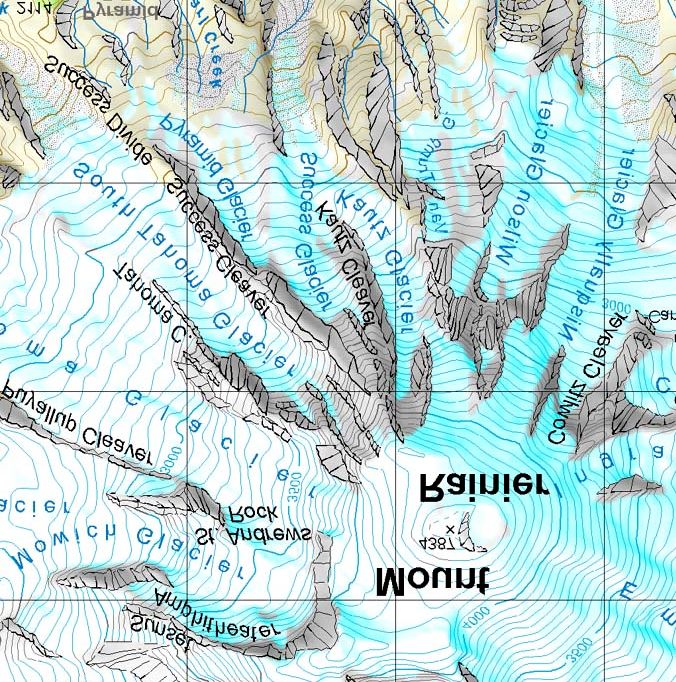
fully tested in four different mapping projects. Figure 6 shows an extract of a map of Mt. Rain-
ier/USA using the ridge line representation (see also Beckel et al. 1998).
Figure 6: Extract of a map of Mt. Rainier/USA Figure 7: Modulation of shape lines (outlines)
using the ridge line representation and filling hachures according to aspect
However, the ridge line method – which has also been used in Eduard Imhof’s school at-
lases – has one major drawback: The depiction is rather difficult to draw because the modulationof the rock faces with their different aspects can only be accomplished by changing the line
thickness of the edge lines. The faces of equal aspect usually stay almost empty. Only very tal-
ented cartographers are able to design readable and esthetical rock depictions using this method.
The digital method still requires a sound knowledge of relief interpretation in order to digitise the
upper and lower edges correctly. Figure 7 shows an extract of the internal guidelines of the Fed-
eral Office of Topography covering the modulation of cliff hachures.
3.3 Implementation of fill hachures
Therefore, at the Institute of Cartography of ETH Zurich, the original cliff software has been de-
veloped further in order to automatically create cliff hachure fillings similar to those in the Swiss
National Map Series (Dahinden, 2000). Instead of relying on edge and ridge lines, continuous
cliff faces with equal slope and aspect are covered with regularly placed hachures, either hori-
zontally or vertically. Like in the ridge line representation they must be modulated according to a
similar illumination model.
Figure 8: Change of parameters for cliff area fill
Areas of equal slope must be digitised by hand. It is possible to choose between single
hachures or areas filled with hachures. The desired direction of hachures (horizontal or vertical)
must also be indicated by the cartographer. The program then fills the area with hachures ac-cording to the spacing rules defined by the Federal Office of Topography (3-4 hachures/mm).
Light modulation and random trembling of the lines are done automatically using the same func-
tions as in the original software for ridge line generation (Hurni et al. 1998). The software again
allows to distinguish between small, medium and large objects, between light and shadow sides
and between concave and convex cliff forms. Figure 8 shows the result when changing different
parameters of the software.
The final implementation of the software was done in C++. As in the first software, the
program has been integrated as a plugin for the graphics software Freehand (Windows version).
A user-friendly interface allows an easy handling of the software. Figure 9, 10 and 11 show first
results of digital fill hachures compared with an extract of the Swiss National Map series.
4. Conclusion
Analytical shading is less time consuming than traditional manual relief shading. Using the pre-
sented local and global techniques, only little time has to be invested to improve the quality of an
analytical shaded relief. Further improvements and developments in the field of computer-aided
shading for cartography are necessary. Particularly, interactive tools are needed to shape digital
elevation models with the goal to locally accentuate geomorphological forms.
As for the digital cliff drawing, the presented results are encouraging as well. The knowl-
edge and the experience of the cartographer is still necessary, but he/she is relieved from painful
manual engraving tasks. Further improvements should include the modelling of geomorphologi-
cal features and structure lines.
Figure 9: Extract of Swiss National Map Figure 10: Cliff drawing using fill hachures
Figure 11: Overlay of original map and new fill
hachures5. Bibliography
Beckel, Julia, Palkovics, Andreas und Peter Sykora (1998): Gebietskarte Mt. Rainier 1:75 000,
University of Vienna,
http://www.gis.univie.ac.at/karto/lehr/exkursion/amex98/u2a/proj.htm
Böhm, Rolf (1998): Kartographische Reliefdarstellung mittels digitaler Bildfilterverfahren. Dis-
sertation. Dresden University of Technology, Institute of Cartography
Böhm, Rolf (1999): Filter-Kombinationsschummerung mittels adaptiver Operatoren. Kar-
tographische Nachrichten, 6: 229–235
Brassel, Kurt (1974): A Model for Automatic Hill-Shading. The American Cartographer, 1/1:
15–27
Dahinden, Tobias (2000): Weiterentwicklung des Programmsystems zur digitalen Felsdarstel-
lung. Semester work, Institute of Cartography, ETH Zurich, 31 p.
Foley, J.D., van Dam, A., Feiner, K., Hughes, J.F. (1990): Computer Graphics: Principles and
practice. Addison-Wesley
Hurni, Lorenz; Neumann, Andreas und Ernst Hutzler (1999): Digital Cliff Drawing for Topo-
graphic Maps. In: Proceedings of the 19th International Cartographic Congress Ottawa,
Vol. 2, 1045–1052
Imhof, Eduard (1982): Cartographic Relief Presentation. New York and Berlin: Walter de
Gruyter
Moellering, Harold and Kimerling, A. J. (1990): A new digital slope-aspect display process.
Cartography and Geographic Information Systems 17/2: 151–159
Patterson, Tom (1997): A Desktop Approach to Shaded Relief Production. Cartographic Per-
spectives, NACIS, 28: 38–40
Yoëli, Pinhas (1959): Relief Shading. Surveying and Mapping, 19 / 2: 229–232
Yoëli, Pinhas (1965): Analytical Hill Shading. Surveying and Mapping, 25/4: 573–579
Yoëli, Pinhas (1966): Analytical Hill Shading and Density. Surveying and Mapping, 26/2: 253–
259
Yoëli, Pinhas (1967): The Mechanisation of Analytical Hill Shading. The Cartographic Journal,
4/2: 82–88
Yoëli, Pinhas (1967): Die Richtung des Lichtes bei analytischer Schattierung. Kartographische
Nachrichten, 2: 37–44
Zhou, X. and Dorrer, E. (1995): An adaptive algorithm of shaded-relief images from DEMs based
on wavelet transforms. Digital photogrammetry and remote sensing '95, SPIE Proceed-
ings Series, Volume 2646: 212–224
Copyright
All relief shadings are based on DHM25 © Federal Office of Topography, Wabern, Switzerland.
Figure 7, 9, 11 © Federal Office of Topography, Wabern, Switzerland
Keywords
Mountain cartography, map design, relief presentation, analytical shading, aerial perspective, lo-
cal adaptations, digital cliff drawingYou can also read