Manual Datafox EVO 3.5 Universal - Flexible data collection with method
←
→
Page content transcription
If your browser does not render page correctly, please read the page content below

Manual
Datafox EVO 3.5 Universal
Flexible data collection with method

© 2021 Datafox GmbH

This document has been created by Datafox GmbH and is copyrighted against third parties. Datafox
GmbH considers all contained information, knowledge and depictions as its sole property. All rights,
including also translation, reprint or copy of the whole document or parts of it, require written con-
sent of Datafox GmbH.
The assertion of all rights in this respect is reserved to Datafox GmbH, especially in case of the
grant of a patent. The handover of this documentation does not establish a claim to the license or
the use of the soft- and hardware. Copies of the floppy disks and CDs may only be made for the
purpose of data backup. Every unauthorized copy of this documentation or the Datafox software will
be prosecuted.

Manual Datafox EVO 3.5 Universal               Seite II                      Datum: 25.06.2021 04.03.17.XX
Alternations

Alternation in this Dokument
Date              Chapter           Discription

26.11.2018        all               Revision the manual to new version 04.03.11.xx

25.06.2021        all               Revision the manual to new version 04.03.17.xx

Alternations of the version
With the device generation IV a new versioning scheme has been introduced. According to this
scheme the file name of the device firmware and the setup program (DatafoxStudioIV) is composed
as follows:

  Product name             XX.              YY.                   ZZ.                    Build
                           Device genera-   Compatibility         Version number         Troubleshooting
                           tion             (which versions       (functional exten-     (with a new version
                                            can be used to-       sion)                  the Build number is
                                            gether)                                      reset)

  z. B. AE-MasterIV        04.              03.                   9.                     04

The use of the manual depends on the version of the firmware and the DatafoxStudioIV or the
DFComDLL. Gather from the following table which manual matches which version. For different
combinations no support can be offered.

Firmware, StudioIV and DLL validity: 4.03.17.xx.

The DatafoxStudioIV is backward compatible. This means that you can configure a device with a
newer DatafoxStudioIV also older firmware, the device only supports the natural functions that are
implemented in the older firmware version. Ie, relevant to the functions that are possible, is always
the manual state that the firmware associated with the Setup equivalent. It is not possible to provide
a centering firmware configured with a stand of DatafoxStudioIV to who is older than the firmware.
recommendation:
If possible, use always the current version of DatafoxStudioIV.
What features are supported in which software versions, is from the file:
Datafox MasterIV, SW version xxx.pdf list as shown.
The file is located on the Datafox DVD and for download on the homepage. Please also note the in-
structions in each chapter in the manual. The updates are available on our website under www.da-
tafox.de download.

Manual Datafox EVO 3.5 Universal                   Seite III                         Datum: 25.06.2021 04.03.17.XX
Inhalt
1.              For your Safety                                                                                                                1
2.              Introduction                                                                                                                   2
  2.1.          Structure of the Documentation ............................................................................... 2
  2.2.          Guarantee Restriction ............................................................................................... 2
  2.3.          Typography of the Documentation ........................................................................... 3
  2.4.          Important General Notes ........................................................................................... 3
3.              Intended Use and Environmental Protection                                                                                      5
  3.1.          Regulations and Notices ........................................................................................... 5
  3.2.          Power supply ............................................................................................................. 5
  3.3.          Environmental Influences ......................................................................................... 5
  3.4.          Mounting outdoors .................................................................................................... 6
  3.4.1.        Temperature ................................................................................................................ 7
  3.5.          Repair ......................................................................................................................... 7
  3.6.          Cleaning ..................................................................................................................... 8
  3.7.          Further Notices .......................................................................................................... 8
  3.8.          Disposal ..................................................................................................................... 9
  3.9.          General Hardware Information................................................................................ 10
  3.9.1.        Hardware equipment ................................................................................................. 10
  3.9.2.        Behavior in case of power failure ............................................................................... 10
  3.9.3.        UPS ........................................................................................................................... 10
4.              System Requirements / Hardware                                                                                               11
  4.1.          System Structure ..................................................................................................... 11
  4.2.          Requirements for Operating Datafox Devices ....................................................... 11
  4.3.          Compatibility ............................................................................................................ 12
  4.3.1.        Firmware File Archive (*.dfz) ...................................................................................... 12
  4.3.2.        Datafox Devices and Device Firmware ...................................................................... 12
  4.3.3.        Device Firmware and Device Setup ........................................................................... 13
  4.3.4.        Device Firmware and Communications DLL .............................................................. 13
  4.3.5.        Communications DLL and DatafoxStudioIV ............................................................... 13
  4.3.6.        DatafoxStudioIV and Device Setup ............................................................................ 13
  4.3.7.        Update / Downgrade .................................................................................................. 14
5.              Device                                                                                                                       15
  5.1.          Commissioning ........................................................................................................ 15
  5.2.          Guideline for Commissioning ................................................................................. 16
  5.2.1.        Set-up of the device ................................................................................................... 16
  5.2.2.        Installation of the Device ............................................................................................ 16
  5.2.3.        Troubleshooting during Commissioning ..................................................................... 16
  5.3.          Operation and display elements of the Evo 3.5 Universal .................................... 17
  5.3.1.        Composition and Operation EVO 3.5 Universal ......................................................... 17
  5.3.2.        Display setup and bios of the EVO-Line 3.5 ............................................................... 18
  5.3.2.1.      Structure display "normal display" 3.5 Universal ........................................................ 18
  5.3.2.2.      Structure Display EVO 3.5 Universal in the Bios menu .............................................. 19
  5.4.          Installation of the 3.5 Universal .............................................................................. 24
  5.5.          Connecting of KYO Onleloc and EVO 3.5 Universal.............................................. 25
  5.5.1.        Connection of digital in-/outputs ................................................................................. 27
  5.5.1.1.      Digital Output one ...................................................................................................... 27
  5.5.1.2.      Digital Output two ...................................................................................................... 27
  5.5.1.3.      Digital inputs .............................................................................................................. 28
  5.6.          Communication of Hardware V4 Devices............................................................... 29
  5.6.1.        Communication via USB ............................................................................................ 29
  5.6.1.1.      Automatic detected connected USB to PC ................................................................. 30

Manual Datafox EVO 3.5 Universal                                  Seite IV                                    Datum: 25.06.2021 04.03.17.XX
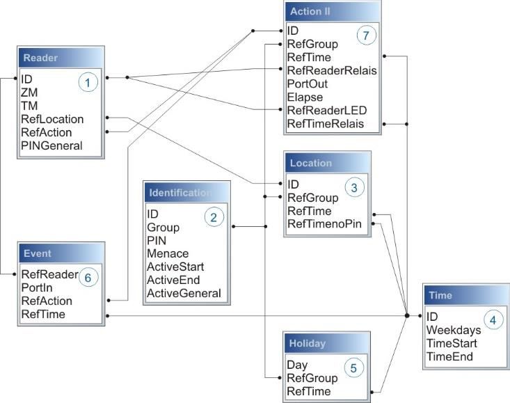
5.6.2.        Installing USB driver for Hardware V4 Devices .......................................................... 31
  5.6.3.        Communication via TCP / IP ...................................................................................... 32
  5.6.3.1.      Communication TCP / IP via network-cable ............................................................... 33
  5.6.3.2.      Communication TCP / IP via wLAN / Wifi ................................................................... 34
  5.6.3.3.      Texas Instruments TI-CC3135 (Generation 2) ........................................................... 35
  5.6.3.4.      Redpine (Generation 1) ............................................................................................. 36
  5.6.3.5.      Connection of the Terminals via TCP/IP DNS / DHCP ............................................... 38
  5.7.          Connection and wiring of the access control ........................................................ 40
  5.7.1.        Configuration and structure of the Access control ...................................................... 40
  5.7.2.        Description of Tables for Access Control 2 ................................................................ 43
  5.7.3.        Status messages of the access control ...................................................................... 46
  5.7.4.        Wiring of the access-control reader ........................................................................... 52
  5.7.4.1.      Connecting of one access-control reader ................................................................... 52
  5.7.5.        Instructions for the electrician for installing the access control system ....................... 56
  5.7.5.1.      Star-shaped bus wiring .............................................................................................. 56
  5.7.6.        Calculation for the power supply of Access modules ................................................. 58
  5.7.7.        Cable length and cable cross section for access wiring ............................................. 59
  5.7.8.        Online functions for the access control ...................................................................... 60
  5.7.8.1.      Online via http-protocol .............................................................................................. 60
  5.7.8.2.      Online via DLL connection ......................................................................................... 63
  5.7.9.        Function extention for access control II ...................................................................... 64
  5.7.9.1.      General description.................................................................................................... 64
  5.7.9.2.      Examples ................................................................................................................... 65
  5.7.9.3.      Description of the table „Action2" ............................................................................... 69
  5.7.9.4.      Additional functions for Access Control ...................................................................... 70
  5.7.9.5.      List Presence ............................................................................................................. 71
  5.8.          RFID Reader ............................................................................................................. 72
  5.9.          Fingerscanner optical sensor ................................................................................. 73
  5.9.1.        Menu Page - Check Finger ........................................................................................ 74
  5.9.2.        Menu page - "Teach in" fingerprints ........................................................................... 74
  5.9.3.        "Training" menu page ................................................................................................ 75
  5.9.4.        Menu page - Delete ................................................................................................... 76
  5.9.5.        Menu page - "Exit ...................................................................................................... 76
6.              Technical Data of EVO 3.5 Universal                                                                                       80
  6.1.          communication modules ......................................................................................... 81
  6.2.          access modules ....................................................................................................... 81
  6.3.          Module digital in and out ......................................................................................... 81
  6.4.          Modules miscellaneous........................................................................................... 81
7.              FAQ                                                                                                                       81
8.              Index                                                                                                                     82

Manual Datafox EVO 3.5 Universal                                 Seite V                                    Datum: 25.06.2021 04.03.17.XX

1.   For your Safety
Safety Information for Datafox Products

                            The EVO 3.5 Universal must only be operated according to the instructions
                            given in the manual. Do no insert any foreign objects into the openings and
                            ports. The device must not be opened. All maintenance work must only be
                            performed by authorized specialists.

                            Some devices contain a lithium ion battery or a lithium battery.
                            Do not throw into fire!

                            Supply voltage:       12 Volt DC
                            See respective type label / technical data.
                            The device must only be operated with a power-limited power supply
                            according to EN 60950-1. If you do not observe these instructions,
    Attention!              the device may be damaged.
                            The following temperature ranges must be observed
                            Working area / storage temperature:                       -20° C bis +70° C
                            Mobile communications module:                             -20° C bis +55° C
                            In areas with cellphone ban, GPRS, WLAN and other cellular modems
                            must be turned off.
                            Persons with heart pacemakers:
                            When using the device, maintain a distance of at least 20 cm between the
                            heart pacemaker and the device in order to avoid possible interferences.
                            Turn the device off immediately if interferences are assumed.

                            Protection class: Observe the technical data of the respective device.
                            In case of laser devices of class 2, the eye is protected by the blink reflex
                            and/or turning reactions if you briefly and accidentally look into the laser
                            beam. The devices may be used without further protective measures. Nev-
                            ertheless, avoid looking directly into the laser beam of the laser scanner

                            Observe the additional notes in the chapter,
                            “Proper use and environmental protection”

                            We declare under our sole responsibility that the product described fullfills the pro-
                            tection requirements of European Directive 89/336 / EEC as amended by 91/236 /
                            EEC, 92/31 / EEC, 93/97 / EEC and 93/68 /. See the manual of the devices for the
                            standards. Evidence is provided by compliance with the following standards:EN
                            55022 : 2010
                                  - EN 55024 : 2010 + A1 : 2015
                                  - EN 61000 – 6 – 2: 2005
                                  - IEC 61000-3-2 : 2014
                                  - IEC 61000-3-3 : 2013
                                  - IEC EN 60950-1 : 2006 + A11 : 2009 + A1 : 2010

Manual Datafox EVO 3.5 Universal                       Seite 1                           Datum: 25.06.2021 04.03.17.XX
2. Introduction
Datafox data terminals have been developed to fulfill the requirements of modern personnel time
recording where users have high demands concerning flexible and elegant design. Furthermore, the
Datafox Embedded-Concept also covers access control. All relevant data can be recorded with
modern technology and be transferred to the analysis software immediately. Billings, calculations or
other analyses can be performed in a timely manner; processes can be monitored and controlled
actively. This saves time and ensures the data quality and immediacy required.
Datafox data terminals are based on the Datafox Embedded-System which is equipped with modern
technology for data collection and of course also data transfer. You make your entries comfortably
via keyboard, touch display, RFID or barcode. The device is available with GPS, GSM, GPRS, USB
etc. It fulfills all conditions for a flexible usage not only for personnel or order time recording but also
for further scopes. This constitutes a real added value. The powerful tools DatafoxStudioIV and DLL
facilitate quick and easy integration in any IT solutions. Due to scalability, numerous options are
available. You can select according to your company's requirements and only pay what you really
need.
2.1. Structure of the Documentation
The manual contains a change history as well as a general part with safety information, the intro-
duction and information concerning system requirements and system structure.
The general part is followed by the main part of the manual. It contains the chapter Product Descrip-
tion Device. In this chapter, device-specific components are described as well as the device's func-
tions.
The final part of the manual provides technical data about the device and a glossary whose purpose
it is to ensure a consistent understanding between user and manufacturer.
2.2. Guarantee Restriction
All installers are responsible for the use of the device and its accessories in accordance with its in-
tended purpose and in compliance with the applicable laws, standards and directives.
All data in this manual has been checked carefully. Nevertheless, errors cannot be excluded. There-
fore, we offer no guarantee nor accept any liability for consequences that derive from errors of this
manual. Of course we are grateful if you point out errors to us. We reserve the right to make modifi-
cations in respect of technical progress. Our general terms and conditions of business apply.
Note:
Due to DatafoxStudioIV, Datafox devices offer many functions and combinations of
functions not all of which can be tested in the case of updates. This applies espe-
cially to setups defined by you as customer. Before updating your device, please en-
sure by tests that your individual setup works without any errors. If you encounter a
problem, please inform us immediately. We will take care of the clarification of the
problem on short notice.
Manual Datafox EVO 3.5 Universal Seite 2 Datum: 25.06.2021 04.03.17.XX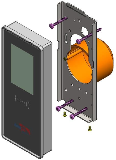
2.3. Typography of the Documentation
FW .................................................................. Abbreviation for firmware (software in the device)
SW .................................................................. Abbreviation for software
HW .................................................................. Abbreviation for hardware
GV................................................................... Abbreviation for global variable
........................ File names
Note:
Useful information which helps you avoiding possible mistakes during the installation,
configuration and commissioning is given here.
Caution:
! ! Here, notes are provided which must be strictly observed. Otherwise, malfunctio
the system will occur.
2.4. Important General Notes
Caution:
! Use the devices only according to regulations and follow the installation, commis-
sioning and operating instructions. Installation and commissioning may only be per-
formed by authorized specialists.
Subject to technical alterations.
Caution:
! Due to technical development, illustrations, function steps, procedures and technical
data may vary slightly.
The Datafox device has been developed for the purpose of creating a flexible and easily inte-
grated terminal for data recording serving for a great variety of applications. The device is robust
and easy to use. Due to the PC setup program, the device is quickly and easily configured for its
application field so that you save time.
Numerous optional features, such as bar code reader, transponder reader, digital inputs etc., en-
able you to use the device for:
PZE - Personnel time recording
AZE - Order time recording
BDE - Operating data recording (I/O-processing)
ZK - Access control
FZDE - Vehicle data recording / telematics
This manual describes the creation of setups with the setup program DatafoxStudioIV
without covering specific applications. Potential problems and difficulties are pointed
out.
This manual describes the functionality of the EVO 3.5 Universal and explains its characteristic fea-
tures. For example, installation, operation and equipment of the device are described.
In order to define the behavior of the device, a setup must be created. For this purpose, the Data-
foxStudioIV has been developed.
Manual Datafox EVO 3.5 Universal Seite 3 Datum: 25.06.2021 04.03.17.XX
With some practice it will be possible to create a complete compilation for the EVO 3.5 Universal
within half an hour. If you need functions that are not available, please contact us.
Note:
If you need support for the compilation of setups, we offer you our services. Due to
our extensive experience with the setup, we work very quickly and can make your
setup even more efficient through useful advices, so that the input at the device can
be performed quickly and securely.
Note:
Due to DatafoxStudioIV, Datafox devices offer many functions and combinations of
functions not all of which can be tested in the case of updates. This applies espe-
cially to setups defined by you as customer. Before updating your device, please en-
sure by tests that your individual setup works without any errors. If you still encounter
problems after thoroughly testing your setup, please inform us immediately. We will
fix the error on short notice.
Manual Datafox EVO 3.5 Universal Seite 4 Datum: 25.06.2021 04.03.17.XX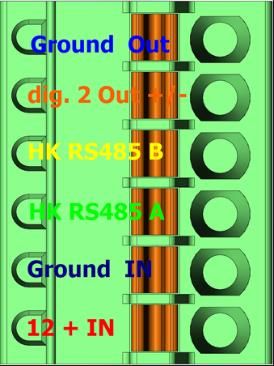
3.     Intended Use and Environmental Protection
3.1.     Regulations and Notices
According to the current state of the art, measures were taken to ensure that the device meets the
technical and legal regulations as well as safety standards. Nevertheless, malfunctions due to inter-
ferences through other devices can still occur.
Please observe local regulations when using the device.

3.2.     Power supply
Only operate the device externally with a limited power source in accordance with EN 60950-1.

If the devices run with rechargeable batteries, note the instructions in chapter "Rechargeable Bat-
tery".

                  Caution:

       !          In the event of non-compliance with these instructions, the device or the battery (if
                  any) can be damaged or destroyed!

In order to ensure maximum battery life, it is recommended to recharge the battery only after com-
plete discharge.

See respective type label of the device EVO 3.5 Universal.

3.3.     Environmental Influences
Extreme environmental influences may damage or destroy the device and should be avoided. This
includes fire, extreme sunlight, water, extreme cold and extreme heat.
See respective type label of the device.

Manual Datafox EVO 3.5 Universal                  Seite 5                        Datum: 25.06.2021 04.03.17.XX
3.4. Mounting outdoors Manual Datafox EVO 3.5 Universal Seite 6 Datum: 25.06.2021 04.03.17.XX
3.4.1. Temperature

The device has an approved temperature range of - 20 ° C to + 70 ° C.
A heater is not necessary for outdoor use.
Due to the inherent heat of the electronics and power supply, the temperatures in the unit are higher
even at ambient temperatures below -20 ° C.
Condensation water only occurs when a cold object comes into the heat and would therefore only
be an issue for mobile devices.
We recommend, if you use the devices outside, then let it running permanently. Both in terms of
temperature as well as condensation, it is recommended to not switch off devices which are used
outdoors.

3.5.     Repair
Except for the battery replacement in mobile devices, Datafox devices are maintenance-free and
must only be opened by authorized professionals. In case of defects, please contact your dealer or
the Datafox service hotline.
If a definite defect is present, you can also send the device directly to Datafox.

https://www.datafox.de/reparaturen.de.html?file=files/Datafox_Devices/PDF/Support/Data-
fox%20Reparaturbegleitformular%20V3%2C%20D-GB_2020.09.25.pdf

Manual Datafox EVO 3.5 Universal               Seite 7                       Datum: 25.06.2021 04.03.17.XX
3.6.     Cleaning

                                        Never use scouring milk or caustic
                                      cleaning agents to remove dirt. Espe-
                                      cially the displays as well as the key-
                                       board and fingerprint modules must
                                                be cleaned carefully.
                                          Wet wipes are permitted with:
                                                        - Water
                                                     - Soapsuds
                                                   - Glass cleaner
                                                      - Sagrotan
                                     - antifect® N liquid (disinfectant for de-
                                               vices in medical field).

                                                    CAUTION
                             Risk of explosion if batteries are replaced improperly.
                             Dispose used batteries according to the instructions.

3.7.     Further Notices
Do not expose the device to strong magnetic fields, especially during operation.
Operate the slots and connections of the device only with the appropriate intended equipment.
Ensure that the device is secured during transport. For reasons of safety, do not use the device
while driving a vehicle. Also ensure that technical equipment of your vehicle is not compromised by
the device.
In order to prevent SIM card misuse, have your SIM card blocked immediately in cases of loss or
theft of the device.

Manual Datafox EVO 3.5 Universal                     Seite 8                       Datum: 25.06.2021 04.03.17.XX
3.8. Disposal
Observe local regulations concerning the disposal of packaging material, used batteries and
scrapped electrical equipment.
This product complies with the EU Directive No. 2002/95/EC, its appendices and the Council Deci-
sion laying down the restrictions of the use of hazardous substances in electrical and electronic
equipment.
The device is covered by the European Directive on Waste Electrical and Electronic Equipment
which came into force on February 13, 2003 and was translated into the legislation of the Federal
Republic of Germany on August 18, 2005.
Do not dispose the device in domestic waste!
As the user, it lies within your responsibility to dispose electrical and electronic equipment via the
designated collection facilities. The correct disposal of electrical and electronic equipment protects
human life and the environment.
For more information regarding the disposal of electrical and electronic equipment, please contact
your local authorities or waste disposal companies.
Manual Datafox EVO 3.5 Universal Seite 9 Datum: 25.06.2021 04.03.17.XX3.9. General Hardware Information 3.9.1. Hardware equipment The devices with hardware V4 are equipped with a flash memory. Depending on the device type or selected option with 4 or 16 MB. For the data, the memory is used as a quasi-ring buffer. If the complete ring buffer is written to full without the data being retrieved, the terminal reports "Memory full", please notify the admin". No fur- ther data is stored during this time. Data that has already been read is gradually transferred. The entire memory is always used to mini- mize the number of accesses per individual memory cell. An ARM microcontroller with 32-bit technology is used. Depending on the type of device, the device has a Goldcap capacitor for buffering the time. This ensures that the watch continues to run correctly for up to one week if the power supply is in- terrupted. In other devices, such as EVO 4.3 or PZE-Master V4, a buffer battery is installed in addition to the capacitor. With this, the watch retains its value for approx. 4 years. The exact equipment can be found in the last chapter Technical Data. 3.9.2. Behavior in case of power failure The device boots automatically when the power supply is switched on again. All data that was not sent or retrieved by the application software before the power failure is stored on the device. These are not lost. After booting, this data is available again. 3.9.3. UPS A corresponding UPS for the V4 hardware is in preparation. We currently recommend equipping the devices with a POE module if a "UPS" is to be used. Then connect the devices via a POE switch and supply the switch via a standard UPS. Manual Datafox EVO 3.5 Universal Seite 10 Datum: 25.06.2021 04.03.17.XX
4. System Requirements / Hardware
4.1. System Structure
The system consists of the Datafox device, the DatafoxStudioIV, the communication DLL and a soft-
ware for processing the generated data.
Create setup Save setup Transfer setup to device
DatafoxStudioIV
Setup Communication- DLL
Software for processing the generated data
4.2. Requirements for Operating Datafox Devices
In order to operate the Datafox device, you need a 230 V power connection for the Datafox power
supply. Depending on the main communication set, you need a corresponding transfer medium or
connection cable.
Main communication:
USB one standard USB-A to USB-micro Cable (see the chapter connection USB).
RS485 a transmission path in accordance with the EIA-485 standard (see Connection
RS485).
GSM/GPRS a distortion-free mobile connection (see Connection GSM).
WLAN WiFi a distortion-free channel to an access point (802.11 b/g) within reach (see
Connection WLAN).
at least one standard Ethernet cable, no „cross over“ (see Connection TCP)
HTTP (internet) via LAN TCP/IP connection with free internet access. The data are
sent to a server.
Note:
With increasing demands on transfer rate and interference immunity, the demands
on the transmission path increase as well with regard to quality (interference immun-
ity).
Manual Datafox EVO 3.5 Universal Seite 11 Datum: 25.06.2021 04.03.17.XX4.3. Compatibility
The compatibility must be observed urgently between:
- Datafox devices and the device firmware
- Device firmware and device setup
- Device firmware and communication DLL
- Communication DLL and DatafoxStudioIV
- DatafoxStudioIV and device setup
4.3.1. Firmware File Archive (*.dfz)
Description
Device files (*.hex) of the MasterIV devices are delivered in a common firmware file archive. It has
the file extension DFZ (stands for Datafox Zip). Now simply the firmware file archives (*.dfz) are indi-
cated instead of the device files (*.hex). This applies to the DatafoxStudioIV and the DLL. The indi-
cation of device files (*.hex) is still possible.
Function of the Archive
The transfer routine of the device file selects the right file from the firmware file archive on the basis
of the hardware options available in the device. Thus, it is guaranteed that all hardware components
available in the device are supported by the corresponding firmware.
Manual Selection of a File
If you do not want to integrate the archive in your installation, you have the possibility to add single
device files from the archive to the installation.
The file format of the firmware file archive is ZIP. Hence, you can open the archive with every stand-
ard ZIP-program. Via the entry "Open With" in the context menu you can select an appropriate pro-
gram for opening the file. If necessary, you can call up a program combined with this file format to
open the file by renaming the file from DFZ to ZIP.
In the archive you find a file named "Inhalt.pdf"; it contains information which file (*.hex) of the ar-
chive matches your device. Extract the desired device file (*.hex) and rename it if necessary. A re-
naming of a file is possible at any time, because all information are in the file itself.
You can state the device file extracted before as device file in DatafoxStudioIV and at calling the
DLL function. It is still tested if the file can be loaded into the chosen device before the transfer
takes place.
4.3.2. Datafox Devices and Device Firmware
Each Datafox device has an electronic flat module. The module has specific hardware equipment
concerning the options (e.g. mobile radio, WLAN, fingerprint, ...). Due to technical conditions, differ-
ent options are mutually exclusive. Currently, not all hardware options can be supported in one firm-
ware file due to limited program memory. This means that each device with specific hardware op-
tions needs a proper firmware to support the hardware options by the software.
Caution:
! Hardware generation V 3 is supported from version 04.02.00.x onwards. The Data-
foxStudioIV is compatible up to and including firmware version 04.01.x.y. Older ver-
sions 04.00.x.y are not supported any more.
Manual Datafox EVO 3.5 Universal Seite 12 Datum: 25.06.2021 04.03.17.XX4.3.3. Device Firmware and Device Setup
The firmware (operating system) of the device and the device setup (*.aes data file = application
program) form a unit. By the device setup, the runtime behavior of the device (the firmware) is deter-
mined. This means the response of the device to input events by the user or the environment (e.g.
digital inputs). In principle, only those functions of the device are executed that are supported by the
firmware and defined via the setup. Prior to the productive commencement, you should therefore
test each setup with the corresponding device or on a device with the same hardware options and
firmware.
4.3.4. Device Firmware and Communications DLL
A firmware supports certain functions, dependent on the hardware options. The communication DLL
is the interface between the firmware and the DatafoxStudioIV or your processing software. There-
fore, the firmware must always have the same or a lower version number as the communication
DLL.
Note:
If your application uses a newer version of the DLL than the firmware does, you can
only use functions that are supported by the firmware.
Otherwise, you will receive an error message (e.g. function not supported) which has
to be analyzed.
4.3.5. Communications DLL and DatafoxStudioIV
Note:
The DatafoxStudioIV and the communication DLL are developed and released as a
bundle. Therefore, they have to be used as a bundle.
A newer version of DatafoxStudioIV does not work with an older DLL.
4.3.6. DatafoxStudioIV and Device Setup
With the DatafoxStudioIV, you create a device setup (application program) for the Datafox device.
That means that in the setup only those functions were defined which were available in the Datafox-
StudioIV version at the time of the setup creation. The DatafoxStudioIV you use for opening a de-
vice setup may thus only be newer but never older than the DatafoxStudioIV version you used to
create the device setup.
Note:
The updates are always available for download on our homepage www.datafox.de.
Caution:
! When new devices are delivered, the latest firmware is loaded on the devices. If you
wish to work with an older firmware version, please perform a downgrade. Please ob-
serve the compatibility notes in the release notes of the respective firmware version.
The data file , Software version .pdf shows which func-
tions are supported by which software release.
You will find the file on the product CD. Please also follow the instructions given in the chapters
of the manual.
Manual Datafox EVO 3.5 Universal Seite 13 Datum: 25.06.2021 04.03.17.XX4.3.7. Update / Downgrade
A firmware update or downgrade is a very sensitive process. Possibly, a reset of the main
communication to RS232 may occur. In any case, consider the information regarding the
compatibility in the software version list.
Firmware Update
Caution:
! Before starting a firmware update, please check on the basis of the software version
list whether there are any version dependencies that must be observed.
For example: when changing from Version 04.00.xx to version 04.01.xx, at least version
04.00.23.769 or higher must be present in order to run the update to version 04.01.xx successfully.
Firmware Downgrade
A firmware downgrade is not recommended.
We are constantly working towards improving the software/firmware; all functionalities are still in-
cluded in new versions. New software always offers better functionalities and possible bugs are
fixed.
Caution:
! When performing a firmware downgrade the firmware has to be transmitted to the
device twice. This has technical reasons. Errors shown on the display of the device
after the first transfer can be ignored.
Manual Datafox EVO 3.5 Universal Seite 14 Datum: 25.06.2021 04.03.17.XX5. Device
Note:
It has to be taken care of a suitable protection from direct sunlight because the synthetic
materials are not 100% UV resistant. Fading simply is an optical defect which does not re-
strict the function of the device.
Caution:
Please keep in mind that MasterIV terminals use a flash memory. According to the man-
ufacturer each memory sector (512 byte) can be written to a maximum of 100,000 times.
The firmware of the terminals distributes the access to the memory sectors, this tech-
nique is called wear levelling. Bad blocks in case of write or read failures are not used
anymore. However, despite this technique it is not advisable to write the memory too fre-
! quently. The application should initialize a new list transfer only after a change of the list
data but not cyclically.
Keep in mind the message - FlashService - in the display of the device. It
means that the live time of the flash memory according to the manufacturer
instruction will be reached soon. Then the device has to be sent to Datafox for
service.
5.1. Commissioning
On delivery, the device is fully functional and configured with a demo setup so that you can test the
input immediately. After establishing the power supply the device will switch on automatically. The
EVO 3.5 Universal automatically starts booting, recognition of the hardware options and loading the
setup. After having finished booting, the device switches to operation. Now itEVO 3.5 Universal is
ready for use.
Note:
On delivery, the main communication is set to USB.
Caution:
! If external modules (e.g. access control, signal processing via the digital inputs) with an
external power supply are used, ensure to comply with all limits (max. voltage and cur-
rent) before commissioning the system.
Manual Datafox EVO 3.5 Universal Seite 15 Datum: 25.06.2021 04.03.17.XX5.2. Guideline for Commissioning
5.2.1. Set-up of the device
This section provides a short guideline for commissioning und links to the corresponding chapters in
the manual.
► Connecting device to current supply
► Setting interface for communication
► Loading setup of the device See manual „DatafoxStudioIV“
5.2.2. Installation of the Device
► Installing the device at the intended location
► Establishing connections for:
o Power:
o Communication:
USB
TCP/IP
TCP/IP wLAN /Wi-Fi
GPRS
RS485
o Digital input
o Digital output
o Analog inputs
o Access-control
► Finishing installation of the device
► Setting for man communication
5.2.3. Troubleshooting during Commissioning
► Please see the FAQ on our website: http://www.datafox.de/faq-de.html.
► Tips:
o Connection to the device cannot be set up via TCP/IP
Check IP in the device and the application (studio)
Ping on IP
Setting "Active Connection" in BIOS? set to NO
Setting "HTTP" in BIOS? set to NO
Manual Datafox EVO 3.5 Universal Seite 16 Datum: 25.06.2021 04.03.17.XX5.3. Operation and display elements of the Evo 3.5 Universal
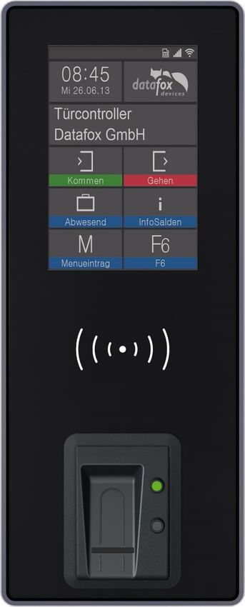
5.3.1. Composition and Operation EVO 3.5 Universal
The terminal includes a capacitive touch.
display and
touchsector
read sector for
transponder
Manual Datafox EVO 3.5 Universal Seite 17 Datum: 25.06.2021 04.03.17.XX5.3.2. Display setup and bios of the EVO-Line 3.5
5.3.2.1. Structure display "normal display" 3.5 Universal
The entire display surface is provided with a touch. Just tap with your finger on the tile you want to
select.
date Tile for state and company logo.
time The logo can be uploaded via the Studio IV.
tile configuration display designer
Texts according to setup (header two) name of EK and
name of input box.
Function buttons according setup
15 buttons are possible an to main
page
tile for „ESC“ if needed
Date Time corresponds to the system time of the device, which is also used for the data records.
Number of records in memory (display up to 99, then 99+).
Communication field with symbols for:
o TCP /IP When this communication is active, this symbol is displayed. .
o Wlan communication
WLAN as main communication
Wlan connected
Wlan Communication is currently active
signal strength wifi
o USB
o USB Host (Save the data to USB stick)
o RS 485
o GPRS With status display e.g.[33] See "Status messages on the display".
Mobile modem is off
Mobile modem is switched on, but no connection to the provider.
Mobile modem is switched on, connection to the provider exists.
o Mobilfunk (BG-96 und EG-95), status display e.g.[33] ] See "Status messages on the display".
Mobile modem is off
X Mobile modem is on, but no connection to the provider.
Mobile modem is on, edge connection to the provider.
, , , , Mobile modem is on, 3G connection to the provider..
, , , Mobile modem is on, LTE connection to the provider.
Display on the display
o The header lines 1 and 2 of the setup are displayed in the main menu.
o The header lines 3 and 4 stored in the setup are displayed in menus and input chains.
o During the transmission of a setup or firmware update, the device enters the system stop and displays this symbol „
Systemstop“ in this window.
o Display in the left part of the window:
= Transponder input (Accept value of transponder)
= Check in (coming) - booking
= check out (going) - booking
Manual Datafox EVO 3.5 Universal Seite 18 Datum: 25.06.2021 04.03.17.XX5.3.2.2. Structure Display EVO 3.5 Universal in the Bios menu
You get into the bios menu when you press the tile company logo for two seconds.
Display of the status icons:
Tap the logo briefly to display the status icons.
You can also change the display of the icons in
the user settings to:
Constantly in place of the logo
Constantly in the "ESC" tile
For 60 seconds instead of the logo
off
Display in Bios Menu:
To select each menu, simply
tap on it with your finger.
If a bios password is set, you are able to enter it here.
Manual Datafox EVO 3.5 Universal Seite 19 Datum: 25.06.2021 04.03.17.XXSystem menu bios:
Menü
>
The respective submenus should be self-ex-
planatory. The respective display depends on
the hardware equipment.
Communication setup: (system menu bios)
Select here the interface for the main communication.
parameter for active-mode (standard = no)
parameter for HTTP (standard = no)
settings of the TCP/IP parameter (IP-address)
Manual Datafox EVO 3.5 Universal Seite 20 Datum: 25.06.2021 04.03.17.XXTCP / IP / DHCP - settings:
If in the device DHCP (yes) is activated, you
aren´t able to change the IP-address.
The IP assigned by the server will be displayed.
TCP / IP - settings:
IP – set
Transponder menu
In the transponder menu you can see which tran-
sponder is installed and which version it has.
(In this example: Mifare and 38022I)
Manual Datafox EVO 3.5 Universal Seite 21 Datum: 25.06.2021 04.03.17.XXSome settings to write the transponders must be adjusted in the setup.
name meaning
Here, the correct transponder
transponder type
type must be specified
In which segment should be
segment no.
written / read
Defines the starting value of the
starting ammount
number to be programmed
When activated, the program-
autoincrement ming value always counts up
the final number
The password to write / read
password
the ID
Note:
If IDs are to be written with a password,
the password must first be programmed on them.
Attention:
In the setup a programmable transponder type and a programmable segment must be
set. Ex.:
! - Hitag 2 -> from segment 4
- Mifare Classic -> from sector 0 block 1
Otherwise, only the type and version of the transponder reader will be displayed.
Manual Datafox EVO 3.5 Universal Seite 22 Datum: 25.06.2021 04.03.17.XXSignal volume:
This menu can be found under
"user settings" "display / sig-
nal volume".
"signal volume"
Touch-Test:
This menu can be found under
„user settings“ „touch“.
Here the correct function of the touch screen can be
checked.
To exit the menu, hold down on the display with two fingers
for three seconds.
Manual Datafox EVO 3.5 Universal Seite 23 Datum: 25.06.2021 04.03.17.XX5.4. Installation of the 3.5 Universal
The wall mounting takes place by means of a wall bracket. We recommend the mounting over a
switch box and additional fix with 4 screws.
The terminal is
mounted at the top.
On the down site
can you fixed the ter-
minal with a screw.
Torx T8
Fixed screw T8
.
Manual Datafox EVO 3.5 Universal Seite 24 Datum: 25.06.2021 04.03.17.XX5.5. Connecting of KYO Onleloc and EVO 3.5 Universal
The KYO Oneloc / Universal is connected via three clamps.
One plug for the TCP/IP connection
One plug for the access control connection
A connector for the RS485 bus
TCP/IP connection:
To connect to a network
digital inputs
digital outputs
Connection for access reader
Power supply for access reader
RS485 - main communication:
Power supply 12V DC
USB interface:
The Micro-USB interface is used to configure the KYO
Oneloc (ZK node). The power supplied by USB is only
sufficient for the configuration.
Note:
Please note that the RS485 bus must not be wired in a star configuration.
No stub lines are supported either.
Explanation:
- Power supply 12V: terminal 3, pin 1 + 2 or via POE
- ZK 485 stands for access bus RS485
- HK 485 stands for main communication RS485
- Voltage output for access control-Bus: terminal 2 pin 1 and terminal 2 pin 2
- DigOut active, e.g. for electric door openers:
a) Configuration to 12V, max. 500mA,
Terminal 3 Pin 5: 12V switched, terminal 3 Pin 6 Ground permanent
b) Configuration to GND (open drain) max. 30V, 2.0A,
Terminal 3 Pin 5: GND switched, positive voltage external or via terminal 2 Pin
1.
clamp 1: 8 pole TCP/IP connector
Manual Datafox EVO 3.5 Universal Seite 25 Datum: 25.06.2021 04.03.17.XXAssignment accord- Assignment accord-
ing to A ing to B
PoE2 Brown Brown
PoE2 White Brown White Brown
RX- Green Orange
PoE1 White Blue White Blue
PoE1 Blue Blue
RX+ White Green White Orange
TX- Orange Green
TX+ White Orange White Green
Clamp 2: 10 pole access bus / IO connector
Digital In Ground
Digital In 2
Digital In 1
Break contact (normally closed free contact
contact) Potential-
Make contact (normally open con-
tact)
Common
Access Control RS485 B access Bus
Access control RS485 A access Bus
Ground Out
+12V Out
Clamp 3: 6 pole RS485 HK connector
digital Out Ground
digital Out active
HK RS485 B main When used as a reader, a
communication 120 Ohm terminating resis-
HK RS485 A main tor is required on the last
communication Kyo Oneloc.
Ground In
+12V In
Manual Datafox EVO 3.5 Universal Seite 26 Datum: 25.06.2021 04.03.17.XX5.5.1. Connection of digital in-/outputs
5.5.1.1. Digital Output one
The digital output 1 is located on the connector strip 2.
This is a potential-free contact.
This can be used via an external voltage source, e.g. as a door opener or connected in parallel to a
push-button. A normally open contact (NO) and a normally closed contact (NC) are available.
Connection example 1 with external power supply:
+ –
Voltage for door opener
max. 30V 2A ~/-
Connection example 2 Parallel connection to an existing pushbutton / connection
Existing locking system with push-button
connection.
Locking systems such as Dorma often have an
external connection for a door opener button.
Here the normally open contact can be con-
nected in parallel to the button for the door Control of a locking system.
opening.
5.5.1.2. Digital Output two
The digital output 2 is located on the connector strip 3.
This is a transistor output.
This can supply either ground or + signal.
Attention:
! If power is supplied via POE, this output must not be used.
Open-
12 V Collector +
+
max. 500mA
+
Manual Datafox EVO 3.5 Universal Seite 27 Datum: 25.06.2021 04.03.17.XXIn Datafox StudioIV, the BIOS mode can be used to change the setting between the two methods.
Under Configuration Device configuration BIOS Switch to BIOS mode and then under "BIOS"
you can switch between "12V" and "Open-Collector".
To change the usage
5.5.1.3. Digital inputs
door contact
supervision
bolt contact
supervision
Manual Datafox EVO 3.5 Universal Seite 28 Datum: 25.06.2021 04.03.17.XX5.6. Communication of Hardware V4 Devices
Caution:
! The type of communication depends on the device.
All possible communications are listed in the device.
Note:
Datafox-devices are able to communicate encrypted.
Read more in the manual for the „DatafoxStudioIV“.
The switching of the communication can be done
via :
1. the system menu bios on the device
2. with firmware version 04.02.04 and up with the function „Switch communication“.
3. from the Firmware version 04.02.04 upwards with the field function „switch communication“.
Read more in the manual for the „DatafoxStudioIV“
Possible communication types are:
1. USB (on PC)
2. USB Host, Save data on a USB-stickGPRS connection with mobile cell network.
5.6.1. Communication via USB
Every EVO-Line Device is equipped with an USB interface.
The Micro-USB-B Port can be connected directly to a PC.
Caution:
! The Terminal works with a USB-B Interface. This means that the device works in slave
mode only. So it is not possible for the device to control any other devices via USB.
Manual Datafox EVO 3.5 Universal Seite 29 Datum: 25.06.2021 04.03.17.XX5.6.1.1. Automatic detected connected USB to PC
If the terminal is connected to a PC it will recognize the connection and will switch the communica-
tion to USB.
DatafoxStudioIV will recognize
the device and a notification
will pop up.
The studio will generate
an entry for the device.
On the device the
following icon is displayed:
It is not necessary to switch the main communication to USB manually.
It’s especially useful for boxed devices.
This will save much time in the parameterizing process.
Note:
If the device is connected to a PC no other connections (for example Wi-Fi) will happen.
If the USB-cable is disconnected, it will automatically switch to the configured main com-
munication.
Manual Datafox EVO 3.5 Universal Seite 30 Datum: 25.06.2021 04.03.17.XX5.6.2. Installing USB driver for Hardware V4 Devices
Installation for Windows 7, 8, 8.1 and 10.
The USB-Driver is a small installer which will do the necessary configuration.
Just launch the .exe file.
Follow the instructions on the screen:
Caution:
! Only use the driver which are delivered with the device!
Note:
If you have DatafoxStudioIV installed, the USB-driver will already be installed on
your PC.
Manual Datafox EVO 3.5 Universal Seite 31 Datum: 25.06.2021 04.03.17.XX5.6.3. Communication via TCP / IP
The setting of the LAN / WLAN parameters is done via DatafoxStudioIV under the menu item "Con-
figuration" "LAN / WLAN – Configuration (*.df0)“.
The LAN / WLAN configurations are saved in a file with the filename extension "*. df0".
Here you have the possibility to edit the file, load it into the Datafox device (upload) or read it from
the device (download).
When reading the WLAN setting from the device, the currently specified file is overwritten.
In the General tab, first of all, you can set the main communication with which the device is
equipped.
- Device with LAN (The first configuration is for LAN connection)
- Device with WLAN
- Device with LAN and WLAN (The first configuration is for the LAN connection)
Caution:
! For TimboyIV only this setting (only wLAN) can be used.
Manual Datafox EVO 3.5 Universal Seite 32 Datum: 25.06.2021 04.03.17.XX5.6.3.1. Communication TCP / IP via network-cable
You can make the IP settings on the "LAN" tab.
Please enter the de-
sired IP address, sub-
net and if necessary a
gateway.
For devices with display, the IP address can also be entered directly on the device.
Press ESC and ENTER simultaneously to enter the Bios menu of the device.
More information can be found in the chapter „bios menu“.
Manual Datafox EVO 3.5 Universal Seite 33 Datum: 25.06.2021 04.03.17.XX5.6.3.2. Communication TCP / IP via wLAN / Wifi General information about the WLAN modules used. There are 2 different WLAN modules that have been integrated into the Datafox devices. 1.) Redpine – installed in the units since 2013. 2.) Texas Instruments TI-CC3135 - installed in the devices since 2021.03. Basically, both modules can be set via the DatafoxStudioIV or on the device itself. The only difference between the modules is that different standards are supported. You can see what each module supports in detail on the following pages. You check with the DatafoxStudioIV via Configuration -> Device configuration (Bios): oder: You have a delivery note and look at the article number 1.) Redpine: Art.Nr.: xxx112 (generation 1) 2.) Texas Instruments CC3135: Art.Nr.: xxx112 A (generation 2) You are checking the Bios menu of the unit: Under: System Menu-> System Menu Bios-> Communication Here you have to set the unit to "WLAN" as the main communication. Under the settings WLAN parameters you have an info menu „Modul Infor- mationen“. Manual Datafox EVO 3.5 Universal Seite 34 Datum: 25.06.2021 04.03.17.XX
5.6.3.3.      Texas Instruments TI-CC3135 (Generation 2)

The module is currently not available for the Universal

This overview shows you which WLAN methods are supported.

The TI-CC3135 module automatically detects the encryption of the AP. Therefore, only the Security
parameter needs to be set. The other parameters (Encryption and Authentication) are detected au-
tomatically.

Routers that operate WPA3/WPA2 in mixed mode can already be used now.

If the networks in the 5Ghz and 2.4Ghz bands have the same name, the network with the better re-
ception quality is selected. This is usually the network in the 2.4Ghz band.

                                   WLAN - Overview of the en-
                                   cryptions
                                           „Infrastructure“

  Secutity:                  Secutity:                Secutity:           Secutity:
  WEP(1)                     WPA2                     WPA3                NON

                                   Encryption and Authentication
                                   Are automatically recognised.
                                     Only the KEY hast o be entered.

               Attention:

  !            We cannot test every Acsess point on the market.
               Therefore, it is not possible for us to guarantee a connection to every AP..

Support for WPA3 and WPA2 Enterprise is planned.

Manual Datafox EVO 3.5 Universal                      Seite 35                   Datum: 25.06.2021 04.03.17.XX
5.6.3.4. Redpine (Generation 1)
This overview shows you which WLAN methods are supported.
- Not supported is WPA (Predecessor of WPA2).
- Not supported is multiple-input multiple-output (MIMO)
- Not supported 5 GHz connections and no mixed operation 2.4 GHz / 5 GHz
- Not supported Authentication via WPA2 Enterprise according to IEEE 802.1x
WLAN / Wifi – overview about
the encriptions and
„Infrastructure“
Security: Security: Security:
WEP(1) WPA2/802.11i None (0)
ohne
Encryption Encryption NO Key
AES / CCMP
WEP64
„AES 128“
WEP128 AES / CCMP +
WEP
Authentication Authentication
Open/None (0) Shared/PSK
Shared/PSK (1)
Attention:
! We cannot test every available Access-Point on the market.
Therefore, it is not possible for us to guarantee a connection to any AP.
Attention:
! multiple-input multiple-output (MIMO) are not supportet. If you switch the access-Point
AP from b/g/n to b/g, use the access-Point only SISO.
https://en.wikipedia.org/wiki/Single-input_single-output_system
When setting the encryption AES or WEP, only one type is used at a time.
The setting AES+WEP means for some access points that AES encryption is performed first and
then additionally encrypted with WEP.
In this case, only set AES.
Manual Datafox EVO 3.5 Universal Seite 36 Datum: 25.06.2021 04.03.17.XXSelect the configuration or location for
which you want to set the WLAN pa-
rameters.
Enter the IP address for the device
here.
This must be the same for every loca-
tion.
All the settings required for an access
point can be made here.
If a key is stored, this will be dis-
played.
If you check this box, the battery
life will be significantly increased
if the device is operated with a
rechargeable battery. Important
for TimeboyIV!
A scan (search) for access points is only carried out after a disconnection after this set time.
Please note the following Attention Box!
Attention:
A search for a new access point requires a lot of energy and drains the battery. Avoid a
! continuous search for an access point when the device is operating at the limit by gener-
ously selecting the pause between scans for new access points (80-120s).
At most access points there is the possibility to set the "Beacon Interval". The higher this
is set, the less power the TimeboyIV needs. Recommendation: Beacon interval >300ms.
The entire file with all settings is transferred to the device. If the device has a display, the location
can be selected in the Bios menu -> Communication -> WLAN. Each location has its own configura-
tion for the WLAN connection. The user therefore has no insight into the dial-in parameters at the
various locations.
Hint:
With automatic selection of the configuration / location, the first attempt is always made to
establish a connection with the default schema.
Manual Datafox EVO 3.5 Universal Seite 37 Datum: 25.06.2021 04.03.17.XXYou can also read