Origin of perpendicular magnetic anisotropy in amorphous thin films - Nature
←
→
Page content transcription
If your browser does not render page correctly, please read the page content below
www.nature.com/scientificreports
OPEN Origin of perpendicular magnetic
anisotropy in amorphous thin films
Daniel Lordan1,3, Guannan Wei1,3, Paul McCloskey1, Cian O’Mathuna1,2 & Ansar Masood1*
The emergence of perpendicular magnetic anisotropy (PMA) in amorphous thin films, which
eventually transforms the magnetic spins form an in-plane to the out-of-plane configuration, also
known as a spin-reorientation transition (SRT), is a fundamental roadblock to attain the high flux
concentration advantage of these functional materials for broadband applications. The present work
is focused on unfolding the origin of PMA in amorphous thin films deposited by magnetron sputtering.
The amorphous films were deposited under a broad range of sputtering pressure (1.6–6.2 mTorr), and
its effect on the thin film growth mechanisms was correlated to the static global magnetic behaviours,
magnetic domain structure, and dynamic magnetic performance. The films deposited under low-
pressure revealed a dominant in-plane uniaxial anisotropy along with an emerging, however feeble,
perpendicular component, which eventually evolved as a dominant PMA when deposited under
high-pressure sputtering. This change in the nature of anisotropy redefined the orientation of spins
from in-plane to out-of-plane. The SRT in amorphous films was attributed to the dramatic change
in the growth mechanism of disorder atomic structure from a homogeneously dispersed to a porous
columnar microstructure. We suggest the origin of PMA is associated with the columnar growth of
the amorphous films, which can be eluded by a careful selection of a deposition pressure regime to
avoid its detrimental effect on the soft magnetic performance. To the author’s best knowledge, no
such report links the sputtering pressure as a governing mechanism of perpendicular magnetisation in
technologically important amorphous thin films.
The soft magnetic properties of thin films as a core material are critical for the realisation of future miniaturised
electromagnetic devices, i.e. micro-transformers and micro-inductors, which essentially requires operation at
high frequencies1–5. To achieve this level of miniaturisation, the pre-requisite of soft magnetic materials are high
saturation magnetisation (Ms), high permeability (µ), high electrical resistivity (ρ), negligible material loss at
high frequencies, and most importantly, ease of m anufacturability6,7 to integrate onto a silicon for a complete
power supply on chip (PwrSoC) concept8. The state-of-the-art soft magnetic materials are amorphous metals
that retain exceptional properties such as high Ms (10–18 kG), high µ (105), ultra-low coercivity (Hc < 1 Oe)
and high ρ (100–150 µΩ cm)9,10. These phenomenal attributes are due to the unique disorder atomic structure,
similar to liquid melts, that retain a high electrical resistivity, zero magnetocrystalline anisotropy, near-zero
magnetostriction, and most importantly, induced in-plane uniaxial a nisotropy11, which makes the amorphous
materials functional for a broad range of applications. Soft magnetic amorphous metals are well investigated
in bulk form; however, the thin-film study of these novel alloys, while retaining their excellent properties for
integrated magnetics, is rather a recent area of interest.
The fundamental roadblock of utilising soft magnetic amorphous films in broadband electromagnetic devices
is perpendicular magnetic anisotropy (PMA)12. The PMA in thin films confines the magnetisation in an out-
of-plane configuration, which eventually results in deteriorated soft magnetic properties, such as high Hc, low
relative permeability (µr), and high material loss due to multimode resonance in the permeability spectrum13.
Several mechanisms have been proposed as an origin of the PMA in amorphous films, such as high degree of
atomic randomness, residual stress, nature of stress (compressive/tensile) and large magnetostriction of the
alloys14,15. The PMA is known to strictly depend on film thickness, alloy composition, nature of fabrication
process, substrate temperature under deposition and post-annealing conditions of fi lms14,16–19. Furthermore, the
same alloy seems to show different spin-orientation when deposited in different sputter chambers, suggesting
its origin is based on deposition parameters and geometry of the sputter chamber. The dynamic nature of PMA,
owning to aforementioned reasons, governs the spins from in-plane to out-of-plane direction, also well-known
as a spin-reorientation transition (SRT), and has been witnessed in many amorphous thin film systems20,21. If the
1
Micro & Nano Systems Centre, Tyndall National Institute, University College Cork, Lee Maltings, Dyke Parade,
Cork T12 R5CP, Ireland. 2Department of Electrical and Electronic Engineering, University College Cork, Cork,
Ireland. 3These authors contributed equally: Daniel Lordan and Guannan Wei. *email: ansar.masood@tyndall.ie
Scientific Reports | (2021) 11:3734 | https://doi.org/10.1038/s41598-020-78950-7 1
Vol.:(0123456789)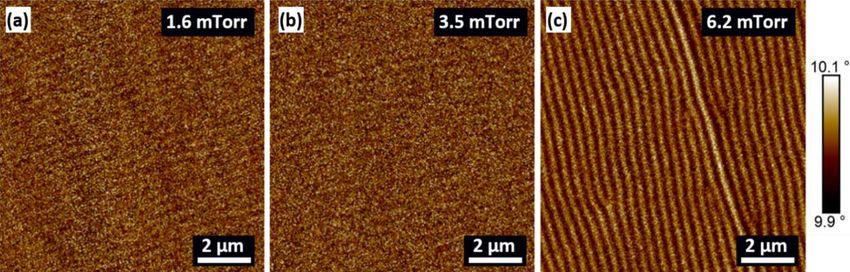
www.nature.com/scientificreports/
Figure 1. (a) The XRD spectrum of Co–Zr–Ta–B films deposited under different argon sputtering pressures
(1.6–6.2 mTorr). (b) SAED pattern of the film deposited under 6.2 mTorr argon pressure.
origin of SRT, why spins transforms from in-plane to out-of-plane configuration for the alloy when deposited
under different sputter tools, is well-understood the amorphous films can be widely adopted in microelectronic
industry for a broad range of soft magnetic applications, including PwrSoC22.
Amorphous thin films are usually deposited by physical vapour deposition (PVD) technique, such as mag-
netron sputtering with argon as a sputter gas23. The power applied to the target determines the deposition rate
of the material, an important parameter to control the thin film growth mechanism. Another critical deposi-
tion parameter of sputtering to consider is the argon sputtering pressure. The argon pressure affects the energy
and angle at which sputtered atoms arrive at the substrate and subsequently condense to form the film. At high
pressures, the sputtered atoms suffer many collisions with the working gas and arrive at the substrate with
reduced momentum, kinetic energy and larger incident a ngles24. The inverse is true for low pressures. In these
two different pressure regimes, one would expect the microstructure of the films to differ. One has to consider
how the amorphous material itself is deposited on the substrate, how it influences the nature of the underlying
magnetism, and consequently, its effects on the ultra-soft magnetic properties for broadband drive applications.
Most recently, a magnetic transition from superparamagnetism to spin glass behaviour of Fe–Zr thin films was
correlated to a very slight change in microstructure of the amorphous films when deposited under different
pressure25. To the author’s best knowledge, no such report links the sputtering pressure as a mechanism of SRT
in amorphous thin films.
The present work is focused on the origin of mechanisms governing the PMA in amorphous thin films depos-
ited by magnetron sputtering. It demonstrates how sputtering deposition pressure can influence the thin film
growth mechanism of amorphous films from a homogeneously dispersed disorder atomic structure to a porous
columnar microstructure, which, consequently, transform the spins from in-plane to out-of-plane configuration
due to the associated PMA.
Results and discussion
Structural properties of as‑deposited films. The atomic structure of each film was analysed using
x-ray diffraction (XRD) in the range of 2θ = 40°–60°. No sharp Bragg’s peak was observed for the films deposited
under different argon pressures of 1.6–6.2 mTorr, as presented in Fig. 1. The absence of Bragg’s peak in the XRD
spectrum shows that the atomic structure of films remained amorphous under various deposition pressures,
which confirms there is no pressure-dependent change on the atomic structure of the films. The sputtering of
films under high pressure can change the atomic structure, and hence, affects the optimum performance of
thin-film materials. For example, reactively sputtered TiN films showed a transition from crystalline to a quasi-
amorphous phase when the sputtering pressure was increased from 2 to 12 mTorr26. Furthermore, a selected area
electron diffraction (SAED) pattern of the 6.2 mTorr film, Fig. 1b, showed a diffuse ring pattern, which further
confirms the localised amorphous structure of the films deposited under highest deposition pressure. The amor-
phous structure of Co–Zr–Ta–B films is vital to retain high electrical resistivity, due to random electron scat-
tering, and ultra-soft magnetic properties, due to absence of magnetocrystalline anisotropy, for high-frequency
applications13,27.
The resistivity (ρ) of each film was measured using a 4-point probe in the centre of each wafer. Note that the
resistivity of the titanium layer was subtracted for each film. All films show a high resistivity, which is critical to
reducing eddy current l osses6. Resistivity values were measured in the range of ~ 117–131 µΩ cm for the present
series of films. A resistivity value of ~ 115 µΩ cm has been reported elsewhere for Co–Zr–Ta–B28. A small vari-
ation in the resistivity values might be due to the various assumptions considered during measurements. One
Scientific Reports | (2021) 11:3734 | https://doi.org/10.1038/s41598-020-78950-7 2
Vol:.(1234567890)
www.nature.com/scientificreports/
Figure 2. SEM images of the thin films deposited at (a) 1.6 mTorr, (b) 3.5 mTorr and (c) 6.2 mTorr along with
corresponding AFM images in (d), (e), (f), (g), (h) and (i).
such assumption is that the film thickness is homogenous across the whole sample. In addition, the resistivity is
influenced by other microscopic features such as voids and rough surfaces, which can be introduced during film
deposition29. A marginal variation in the resistivity of the films deposited under a broad pressure range further
suggest the amorphous nature of the atomic structure at the local atomic scale, hence it is in good agreement
with the XRD and SAED structural observations (Fig. 1).
Scanning electron microscopy (SEM) images show the surface morphology of the 1.6 mTorr, 3.5 mTorr, and
6.2 mTorr pressure films, as presented in Fig. 2. The number of grains and grain size for each film was calculated
using ImageJ analysis s oftware30. The lower pressure film of 1.6 mTorr, see Fig. 2a, displays a dense microstructure
of ~ 784 grains with an average grain size of ~ 40 nm (grain size herein was measured as the width of the grains).
The 3.5 mTorr pressure film has ~ 208 grains with an average size of ~ 78 nm. Conversely, the higher-pressure
film of 6.2 mTorr displays a much denser microstructure when compared to the other two films, as presented
in see Fig. 2c. A total of ~ 1122 grains were counted for this film with an average grain size of ~ 34 nm. Further,
atomic force microscopy (AFM) was performed over a similar-sized area, as presented in Fig. 2d–f, which
revealed similar characteristics of the films. The grain size of the 1.6, 3.5 and 6.2 mTorr films (averaged over 10
grains) was found to be ~ 36 nm, 64 nm and 35 nm, respectively, from the AFM images. Later, a larger scan area
(10 µm × 10 µm) was imaged to investigate surface topography. Root mean square roughness of 1 nm, 1.6 nm,
and 1.2 nm were measured over the whole scan area for the 1.6 mTorr, 3.5 mTorr, and 6.2 mTorr pressure films,
respectively. The small roughness values suggest quite a smooth surface of the films, as can be seen in Fig. 2g,h,i.
Further, the thin film growth process was investigated by transmission electron microscopy (TEM) imaging
of the cross-section of the films thinned by focused ion beam (FIB). Figure 3 presents the TEM micrographs of
the films deposited at the lowest (i.e., 1.6 mTorr) and highest (i.e., 6.2 mTorr) deposition pressures. Ultra-smooth
growth of films was observed in 1.6 mTorr pressure film, see Fig. 3a, thanks to the homogeneous disordered
Scientific Reports | (2021) 11:3734 | https://doi.org/10.1038/s41598-020-78950-7 3
Vol.:(0123456789)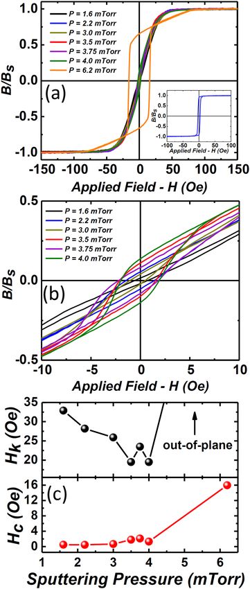
www.nature.com/scientificreports/
Figure 3. TEM image of the cross-section of 250 nm film deposited under different sputtering pressures, (a)
1.6 mTorr, (b) 6.2 mTorr.
atomic structure that makes the amorphous films viable for a broad range of MEMS applications. Contrarily, the
microstructure of film was remarkably distinct under high-pressure deposition, thus proposing a fundamen-
tal divergence in the mechanism of the thin-film growth process. Cross-sections of the film deposited under
6.2 mTorr is illustrated in Fig. 3b, suggesting that high-pressure deposition leads to a porous columnar growth
structure. The size of the voided columnar regions measured using TEM is ~ 36 nm, which is on the same order
of magnitude for the grain size estimated from the SEM (~ 34 nm) and the AFM (~ 35 nm), see Fig. 2c,f. The
pressure-dependent change in the microstructure of amorphous films could cause a different nature of anisotropy
energies to emerge, i.e., magnetostatic or magnetoelastic, that might be competitive enough to influence the
global magnetic behaviours of the films, and, eventually, soft magnetic performance of the films.
The microstructure of sputtered films results from the energy of the sputtered atoms and the angles at which
they arrive at the s ubstrate25,31. At low pressures, the sputtered atoms have a long mean free path and overcome
a shadowing effect during the initial nucleation of the film due to being highly energetic. This shadowing effect
is an interaction between the initial roughness of the substrate and the angle at which sputtered atoms arrive at
the substrate. Thus, in this low-pressure regime, the sputtered atoms from the Co–Zr–Ta–B arrive at the substrate
with high energy, strike the material out, and consequently, no inter-columnar voids are produced. Diversely, for
the higher argon pressure of the 6.2 mTorr, the mean free path of sputtered Co–Zr–Ta–B atoms is reduced due to
scattering with the working argon gas and creates a bigger angle of incidence when arriving at the substrate. In
this high-pressure regime, the sputtered atoms are less energetic when arriving at the substrate, and the material
is unable to overcome the shadowing effect during the initial nucleation of the film. The material preferentially
grows on higher surface features and prevents deposition on shadowed regions. This shadowing effect produces
inter-columnar voids on the substrate, as the atoms are unable to be incorporated at grain b oundaries32. This is
in agreement with Thornton’s growth model of thin films, which suggests how high working gas pressure results
in a porous columnar type growth structure due to this pinning effect during the initial nucleation of the fi lm33.
Kim et al.25, demonstrated that high pressure during sputtering lead to a porous columnar microstructure for
amorphous Fe–Zr films, which eventually, transforms the nature of the underlying magnetism. The solidus
melting temperature of the Co–Zr–Ta–B alloy was found as ~ 1021 °C by calculating the phase diagram using
Pandat software (version 2019, https://computherm.com/)34. The temperature of the substrate during low pres-
sure (1.6 mTorr) growth was measured as ~ 110 °C by using temperature sensitive labels. Note that this value is an
upper bound. As the pressure increases, the atoms arrive at the substrate with less energy, decreasing the substrate
temperature during deposition. This substrate temperature value results in a maximum Ts/Tm ratio of ~ 0.1, and
thus the high-pressure film is consistent with a Zone 1 type growth formation from the Thornton model. Zone
1 type growth is associated with the formation of a columnar microstructure with voided boundary regions
and occurs when the ratio of Ts/Tm is low in conjunction with an elevated working gas p ressure35. The absence
of porous columns in the low-pressure films is caused by the coating atoms having sufficient energy to fill the
voided regions due to lack of collisions with the working gas, causing the coating atoms to arrive at near normal
incidence. The pinning of sputtered atoms during the initial nucleation of the film may explain why the high pres-
sure regime film (i.e. 6.2 mTorr) has a larger number of grains as seen in the SEM and AFM images in Fig. 2c,f.
DC magnetic properties. Figure 4a presents the BH loops of the films measured along the hard anisotropy
axis, while the inset shows a typical easy anisotropy axis BH loop of the film deposited under 1.6 mTorr pres-
sure. A well-defined easy and hard anisotropy axis of BH loops show that a significant uniaxial anisotropy was
Scientific Reports | (2021) 11:3734 | https://doi.org/10.1038/s41598-020-78950-7 4
Vol:.(1234567890)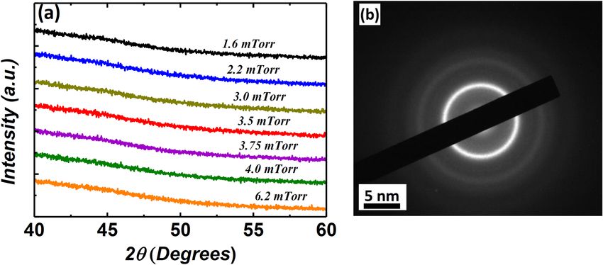
www.nature.com/scientificreports/

                                  Figure 4.  (a) BH loops of Co–Zr–Ta–B thin films deposited under different argon sputtering pressure. Inset
                                  shows the easy axis hysteresis loop of the 1.6 mTorr film, (b) Zoomed-in area of the BH loops of films deposited
                                  at 1.6–4 mTorr pressure showing the evolution of perpendicular magnetic component, (c) Anisotropic filed (Hk)
                                  and coercivity (Hc) versus argon sputtering pressure for all films.

                                  induced during the deposition process of films deposited in low-pressure regime (1.6–4 mTorr). Contrarily, the
                                  nature of magnetic anisotropy was surprisingly different in the high-pressure films (i.e., 6.2 mTorr). Interestingly,
                                  the zoomed-in region of hard anisotropy loops of low-pressure films (1.6–4 mTorr), presented Fig. 4b, show
                                  two distinct slopes before saturation. Nevertheless, the strength of the slope, i.e. close to zero-field, is feeble as
                                  compared to the 6.2 mTorr film. More importantly, the slope of the loops continuously emerged as a function
                                  of deposition pressure, thus suggesting a pressure-dependent evolution in the nature of magnetic anisotropy.
                                  Furthermore, the effect of the evolution of magnetic anisotropy is evident in the resultant anisotropic field (Hk)

Scientific Reports |   (2021) 11:3734 |                https://doi.org/10.1038/s41598-020-78950-7                                                     5

                                                                                                                                                 Vol.:(0123456789)
www.nature.com/scientificreports/
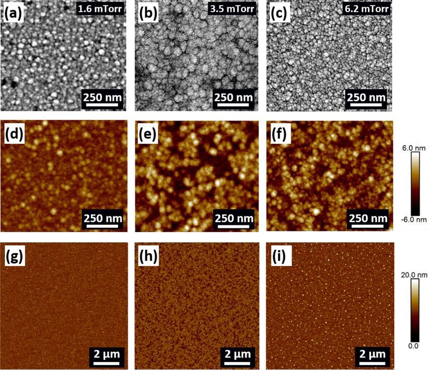
Figure 5. MFM images performed at the remnant state of magnetisation of the films deposited under different
sputter pressure, (a) 1.6 mTorr, (b) 3.5 mTorr, (c) 6.2 mTorr.
of the films measured using the BH loops; see Fig. 4c. The highest uniaxial Hk ~ 32.92 Oe was measured for the
1.6 mTorr film. The Hk values decreased as a function of increasing pressure, due to the competing uniaxial and
perpendicular components, and approached a minimum Hk ~ 19.51 Oe in the pressure range of 3.5–4 mTorr. The
dramatic increase in Hk ~ 75 Oe of 6.2 mTorr film was due to the isotropic BH loop with no discernible easy or
hard magnetic axis ascribed to the dominant PMA component. Another evolution in the coercivity (Hc) of films
was observed, which steadily increased with sputtering pressure with a minimum Hc ~ 0.49 Oe at 1.6 mTorr to an
undesirable large Hc ~ 15.95 Oe for 6.2 mTorr pressure (Fig. 4c).
A double-sloped hysteresis, known as a transcritical loop, is indicative of perpendicular magnetisation, where
the slope emerging before the saturation shows the PMA component36. Films in the pressure range of 1.6–4 mTorr
display both uniaxial in-plane anisotropy and a PMA, as evident from the double-sloped loops presented in
Fig. 4b. It further illustrates that the PMA component is deposition pressure-dependent, and once the pressure
was increased from 4 to 6.2 mTorr, the PMA component becomes dominant. The resultant hysteresis of the
6.2 mTorr films remains isotropic and displays a transcritical shape, which is attributed to the dominant out-of-
plane magnetisation37. This phenomenon is known as SRT, where magnetisation transforms from in-plane to
out-of-plane configuration and has been recently reported for many amorphous thin fi lms14,20.
Magnetic force microscopy (MFM) images were obtained at the remnant state of magnetisation for the follow-
ing films; 1.6, 3.5 and 6.2 mTorr, as presented in Fig. 5. The 1.6 mTorr and 3.5 mTorr pressure films display some
faint striped domain patterns, as seen in Fig. 5a,b. This is in good agreement with the BH loops that manifested a
weak PMA component in the films deposited under low-pressure. However, once the pressure increased beyond
the critical point to 6.2 mTorr, a distinct striped domain pattern emerged, as seen in Fig. 5c. A well-defined striped
magnetic domain suggests that the easy axis magnetisation of the film resides perpendicular to the plane. The
difference in contrast of striped domains is related to the orientation of the magnetic spins, which are pointing
either upward or downward in relation to the film p lane36. The change in sign of the magnetisation component
between domains causes a reduction in the effective anisotropy energy and hence, explains why a higher external
field (i.e., > 75 Oe) is required to saturate the 6.2 mTorr film38,39.
AC magnetic properties. The permeability of the films was measured in the frequency range of
1 MHz—9 GHz, as presented in Fig. 6. The films deposited under low-pressure (1.6–4 mTorr) show high perme-
ability and ferromagnetic resonance frequency (fFMR > 1 GHz). This could be ascribed to the dominant uniaxial
anisotropy induced during deposition pressure of the films, as seen from BH loops (Fig. 4). Inset Fig. 6a shows
the real permeability values (µʹ, quoted at f = 40 MHz) as a function of Ar sputter pressure. The 1.6 mTorr film
displayed the lowest µʹ ~ 366 for low-pressure regime films and is related to the large Hk ~ 32.92 Oe. The 3.5 mTorr
and 4 mTorr films having the lowest Hk ~ 19.5 Oe display the highest µʹ ~ 509 and ~ 646, respectively. The imagi-
nary component of permeability (µʺ) of each film is negligibly small up to 100 MHz, as presented in Fig. 6b.
The smaller µʺ is due to the thickness of the films, which is below the skin depth of the Co–Zr–Ta–B a lloy40.
Interestingly, a small kink at the shoulder of the main fFMR was observed in all films, except for the 6.2 mTorr
sample. The emergence of multiple peaks before the main FMR could be attributed to the heterogeneous amor-
phous structure of the films, as reported by the same authors e lsewhere13. More interestingly, the 6.2 mTorr
film displayed low µʹ ~ 144 and multiple resonance peaks after the main f FMR both in the real and imaginary
permeability spectra. The low µʹ and multiple peaks may have emerged due to the strong PMA component, as
confirmed from BH loops and domain imaging.
The Landau–Lifschitz–Gilbert (LLG) equation (see Eq. 1) was used to calculate the Gilbert damping constant,
α, for the films with dominant in-plane uniaxial anisotropy (i.e., films deposited under low deposition pressure)41
� � � �
γ 2 Ms · Hk − Ms + iαω γ
tanh (1+i)t
2δ
µ= 1+ 2 · (1)
γ Hk · (Hk + Ms ) − ω2 + iωαγ · (2Hk + 4πMs ) (1+i)t
2δ
Scientific Reports | (2021) 11:3734 | https://doi.org/10.1038/s41598-020-78950-7 6
Vol:.(1234567890)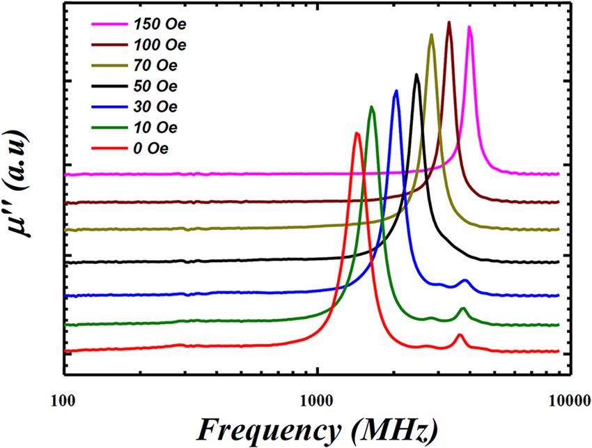
www.nature.com/scientificreports/
Figure 6. (a) High-frequency real permeability (μʹ) spectrum of for films deposited under different sputtering
pressure (1.6–6.2 mTorr). The inset shows the values of μʹ at f = 40 MHz versus argon sputtering pressure. (b)
High-frequency imaginary permeability (μʹʹ) for all films. Note the emergence of multiple peaks after the main
f FMR for the films deposited under the highest sputtering pressure (i.e., 6.2 mTorr) in the present series of films.
The inset shows the Gilbert damping factor, α, of films deposited under different argon sputter pressures.
where MS is the saturation magnetisation,√Hk is the anisotropy field, γ is the gyromagnetic ratio, t is the thick-
ness of the film and δ is the skin depth as 2ρ/(ω · µ0 · µstatic ). The damping factor, α, describes the ease of the
spins to undergo magnetisation reversal at high frequencies42. One would expect the loss of the material to be
substantial at high frequencies if the value of α is significantly large. The α increased gradually as a function of
Scientific Reports | (2021) 11:3734 | https://doi.org/10.1038/s41598-020-78950-7 7
Vol.:(0123456789)www.nature.com/scientificreports/
Figure 7. High-frequency imaginary permeability (µʹʹ) of the 6.2 mTorr films under a bias field from 0 to 150
Oe along easy anisotropy axis. The multiple resonance peaks after main FMR peak disappears when the bias
field ≥ 70 Oe.
deposition pressure, as shown in Fig. 6b inset hence suggesting how emerging PMA, however feeble, is correlated
to the damping loss of the films that could rise at high frequencies to undermine the performance of the material.
The high-frequency permeability spectrum strongly depends on the magnetic domain structures of the
material. Multiple f FMR peaks normally can originate from stripe magnetic domains due to perpendicular
magnetisation43. The effect of magnetic domain structure on the permeability spectrum of the films can be
negated, if any, to a single domain by saturating the films using a bias magnetic field. The in-plane biased mag-
netic field from 0 to 150 Oe was applied along the easy-axis of 6.2 mTorr film and response of multiple resonance
peaks was investigated, as presented in Fig. 7. The multiple peaks only disappeared when the bias-field increased
to 70 Oe, that is similar to the measured Hk ~ 75 Oe required to saturate the 6.2 mTorr film to a single magnetic
domain (see Fig. 4a). This concludes that the multiple peaks after main FMR in the high-pressure film may have
originated from the dominant PMA component, and disappeared when using a bias field. Furthermore, these
multiple peaks were missing in the AC permeability spectra for low-pressure regime films (1.6–4 mTorr), see
Fig. 6, which further confirms the dominant uniaxial anisotropy in low-pressure films, as seen in the BH loops
(Fig. 4).
Furthermore, OOMMF micromagnetic s imulations44 were performed to verify the effect of PMA on the
emergence of multiple peaks after the main FMR. 2D static micromagnetic simulations (78 × 25 grids) were
constructed for the film thickness 250 nm with, (1) a dominant PMA for the film deposited under 6.2 mTorr
(Fig. 8, Inset 1), and (2) a significant in-plane uniaxial anisotropy for the film with strong biased field (Fig. 8, Inset
3), following the method introduced by Youssef et al.45. The in-plane easy axis is along the stripe domains and
defined as the x-axis, the thickness is defined along the z-axis, and periodic structures with vortex-like domain
walls were constructed along the y-axis. The PMA was set as 0.3 × 10⁵ erg/cm3 for films deposited under 6.2 mTorr,
which results in a domain width ~ 200 nm comparable to the domain width as seen in the MFM image presented
in Fig. 5c. In this zero-field cross-sectional equilibrium magnetisation configuration, mx was considered as 0.57,
where mx is the ratio of magnetic remanence over magnetic saturation. This is comparable with the BH loop
measurements for the high-pressure film. The µʺ of the zero-field microwave permeability (excited along the
y-axis) were simulated, which showed multi-peaks after the main FMR (Fig. 8, solid black line), similar to the
experimental results presented in Fig. 6b. The Fig. 8 inset 2 shows the magnitude distribution at the secondary
peak position, where the red colour indicates a larger magnitude and the blue colour indicates a smaller magni-
tude, which shows that the secondary peaks are mainly contributed by localized resonances, similar to the work
reported elsewhere45. While the simulation results for films with strong in-plane uniaxial anisotropy (6.2 mTorr
films with strong in-plane biased field) only show a single FMR peak, shown in Fig. 8 (solid red line), similar
to the result under > 70 Oe biased field in Fig. 7. Conclusively, simulation results further confirm that multiple
peaks in high-pressure films emerged due to the dominant PMA component, which disappeared when PMA
became feeble due to applying a suitable in-plane biased field.
The PMA shows the detrimental effects on the high-frequency soft magnetic properties of films, such as
high Hc, low permeability, and high material loss due to multimode resonance in the permeability spectrum,
as discussed in detail in previous sections. Several mechanisms have been proposed as an origin of PMA in
amorphous thin films. For example, Sharma et al.14 concluded that the residual stress and high degree of atomic
randomness are the fundamental reasons for the emergence of the PMA in Co–Fe–B–Ta amorphous films. The
residual stress of each film was measured by calculating the difference in the curvature of the wafer pre- and
post-deposition of the films. The stress values remained in the range of 0.15–0.27 GPa for the series of the
investigated films, though no systematic change was observed. All films revealed compressive stress in nature
where the films stretch after deposition. The target alloy used for sputtering was in direct line of sight with the
substrate rather than utilising oblique angle deposition, which tends to promote the formation of tensile stress
Scientific Reports | (2021) 11:3734 | https://doi.org/10.1038/s41598-020-78950-7 8
Vol:.(1234567890)www.nature.com/scientificreports/
Figure 8. OOMMF simulation of the high-frequency imaginary permeability (µʺ) for films with different
magnetisation configurations. The solid black line shows the simulated µʺ of the film with a dominant PMA,
while the solid red line indicates the µʺ of the film with strong in-plane uniaxial anisotropy. In-plane easy axis
is along the x-axis, the thickness is along the z-axis, and the configuration is periodic along the y-axis. Inset 1
shows the cross-section of the static magnetisation configuration (arrows indicate the magnetisation direction,
the green colour indicates the magnetisation direction along the positive x-axis, the orange colour shows the
magnetisation along the negative x-axis). Inset 2 shows the FMR magnitude distribution (red colour indicates
a larger magnitude, the blue colour indicates a smaller magnitude). Inset 3 shows the static magnetisation
configuration of the films. All inset images were generated using OOMMF micromagnetic software (version 1.2
(beta), http://math.nist.gov/oommf).
due to the increase in inter-columnar voids46. A long mean free path due to low deposition pressure results in
the sputtered atoms arriving at the substrate at near-normal incidence, and compressive type stress is typically
seen under this m ode47. One would expect the stress of the high-pressure film of 6.2 mTorr to be tensile in nature
due to the increased incident angle of arriving atoms. However, the existence of porous inter-columnar voids,
see Fig. 3b, can reduce the effect of tensile s tress32. The incorporation of oxygen from the surrounding air after
removing the film from the vacuum chamber nullifies the tensile stress, and eventually, induces compressive
residual stress48. In addition, porous films are also susceptible to impurity formation when exposed to ambient
atmospheric conditions after deposition. This might be the reason for the white dot contaminants, as seen in the
AFM image of the 6.2 mTorr films in Fig. 2i. Conclusively, the residual stress of all films remained compressive
in nature and comparable in magnitude, suggesting that it should not be the dominant factor to influence the
underlying mechanism of magnetism.
A correlation between thin film growth mechanism from a homogeneous disorder atomic structure to a
porous inter-columnar void, the emergence of PMA from a feeble strength to a dominant component, and
evolution of single-mode FMR to a multimode resonance suggests the origin of perpendicular magnetisation
in the high-pressure film is related to the remarkable shape anisotropy in out-of-plane direction originated by
the columnar growth of the films. To the author’s best knowledge, this is the ever first report that links the high
sputtering pressure to the columnar structure of the films as a mechanism of perpendicular magnetisation in
amorphous thin films.
Conclusions
The Co–Zr–Ta–B amorphous films of 250 nm thickness were deposited using DC magnetron sputtering from a
single alloy target. The effect of argon sputtering pressure (1.6–6.2 mTorr) on the thin film growth mechanisms,
global magnetic behaviours, magnetic domains, and high-frequency permeability response was investigated. The
structural analysis of the films confirmed the amorphous nature of the atomic structure at the local scale. Thin-film
growth mechanism drastically changed from a homogeneous structure to a porous columnar structure when the
deposition pressure elevated from a low (1.6 mTorr) to a high-pressure (6.2 mTorr) regime. The columnar growth
of the films was ascribed to the lower energy of sputtered atoms arriving at the substrate and a self-shadowing
effect. The films deposited under low-pressure retained dominant in-plane uniaxial magnetic anisotropy, though
an incremental increase in the PMA component as a function of deposition pressure was observed, as confirmed by
the evolving BH loops and faint stripe domain patterns. The anisotropy of the films deposited under high-pressure
completely transformed to perpendicular, thus resulting in an out-of-plane magnetic configuration, as confirmed by
isotropic transcritical BH loops, stripe magnetic domain pattern, and multiple mode resonance in high-frequency
permeability spectrum. The OOMMF micromagnetic simulations further confirmed the origin of multiple reso-
nance peaks was associated with the dominant PMA in high-pressure films. We conclude that the origin of PMA
in the present amorphous films is associated with porous columnar microstructure, grown due to the high sputter
deposition pressure. Thus, we suggest that the ultra-soft magnetic performance of amorphous films can be retained
by carefully selecting a low-pressure deposition regime to avoid the porous columnar growth of films.
Scientific Reports | (2021) 11:3734 | https://doi.org/10.1038/s41598-020-78950-7 9
Vol.:(0123456789)www.nature.com/scientificreports/
Methods
Amorphous films of C o84–Zr4–Ta4–B8 (atomic %) alloy were deposited by a DC-magnetron sputtering (Nordiko
Advanced Energy NDX 2500-W) deposition technique. DC magnetron sputtering was used on an 8″ single
alloy target (Testbourne Ltd., 99.9% purity) with a throw distance of 5.5 cm. The same alloy target was used
for all deposition runs. The sputtering chamber was pumped down to a base pressure of ~ 10–7 mbar. Prior to
deposition, the substrates (100 mm diameter Si/SiO2, 0.25 um thermal oxide) were cleaned by generating an RF
plasma in the sputtering chamber at 1 kW for 25 min using high purity argon gas. An adhesive layer of 20 nm
thickness of Ti was deposited prior to the deposition of the magnetic film. An aligning magnetic field was used
during deposition, and a DC power of 1 kW was applied to the target material. The deposition was in a bottom-
up configuration and the wafers were sitting on a carousel. The carousel rotation throughout the deposition was
kept constant at 10 revolutions per minute (RPM). A Dektak profilometer was used to determine the stress and
thickness of each film. The deposition rate was calibrated at 22.7 nm/min by measuring the step height of the
films. The thickness of the magnetic material was kept constant at 250 nm for the whole series of films. The flow
rate of the argon gas was adjusted using a mass flow controller before every deposition run to achieve the desired
argon pressure for the sputtering of the magnetic alloy. Seven films were deposited under the same deposition
parameters except varying the argon pressure in the range of 1.6–6.2 mTorr.
XRD was used to determine the atomic structure of each film (XRD, Phillips Xpert diffractometer, Cu Kα
− 1.54 Å). Surface morphology images were taken with a SEM and AFM (Bruker Dimension Icon). The solidus
temperature of the Co–Zr–Ta–B alloy was found using Pandat software (version 2019, https: //comput herm. com),
based on the thermodynamics database. The temperature of the substrate during deposition was measured using
temperature-sensitive labels (Radionics). TEM lamella cross-sections were prepared using a DualBeam FIB (FEI
Helios NanoLab 600i). The microstructural analysis was performed using a high-resolution transmission elec-
tron microscope (HR-TEM, Jeol 2100, 200 kV) using a double tilt sample holder. The resistivity of each film was
measured using a 4-point probe setup and the resistivity of the titanium layer was subtracted in each case. The
static magnetic properties were investigated by using a B-H loop tracer (SHB, MESA 200 HF) on the 100 mm
wafer. Magnetic domain images were taken over a 10 µm × 10 µm area using MFM (Bruker Dimension Icon) at
the remnant state of the magnetisation along with surface topography images. A high-frequency Permeameter
(Ryowa, PMM 9G) was used to measure the permeability of 4 mm × 4 mm samples taken from the centre of
each wafer. Micromagnetic simulations were undertaken using OOMMF micromagnetic software (version 1.2
(beta), http://math.nist.gov/oommf).
Received: 20 July 2020; Accepted: 19 November 2020
References
1. Wang, F. et al. Soft magnetic Fe–Co-based amorphous alloys with extremely high saturation magnetization exceeding 1.9T and
low coercivity of 2A/m. J. Alloys Compd. 723, 376–384 (2017).
2. Wang, N., O’Donnell, T., Roy, S., McCloskey, P. & O’Mathuna, C. Micro-inductors integrated on silicon for power supply on chip.
J. Magn. Magn. Mater. 316, e233–e237 (2007).
3. Fergen, I., Seemann, K., von der Weth, A. & Schüppen, A. Soft ferromagnetic thin films for high frequency applications. J. Magn.
Magn. Mater. 242–245, 146–151 (2002).
4. Podder, P. et al. In CIPS 2020; 11th International Conference on Integrated Power Electronics Systems. 1–4.
5. Pavlovic, Z. et al. In CIPS 2020; 11th International Conference on Integrated Power Electronics Systems. 1–5.
6. Gardner, D. S. et al. Review of on-chip inductor structures with magnetic films. IEEE Trans. Magn. 45, 4760–4766 (2009).
7. Korenivski, V. GHz magnetic film inductors. J. Magn. Magn. Mater. 215, 800–806 (2000).
8. Mathúna, C. Ó., Wang, N., Kulkarni, S. & Roy, S. Review of Integrated Magnetics for Power Supply on Chip (PwrSoC). IEEE Trans.
Power Electron. 27, 4799–4816 (2012).
9. Fish, G. E. Soft magnetic materials. Proc. IEEE 78, 947–972 (1990).
10. Luborsky, F. E., Frischmann, P. G. & Johnson, L. A. Amorphous materials—A new class of soft magnetic alloys. J. Magn. Magn.
Mater. 19, 130–137 (1980).
11. Warlimont, H. The impact of amorphous metals on the field of soft magnetic materials. Mater. Sci. Eng. 99, 1–10 (1988).
12. Yu, J. et al. Thermal annealing effect on FeCoB soft underlayer for perpendicular magnetic recording. J. Appl. Phys. 91, 8357–8359
(2002).
13. Masood, A., McCloskey, P., Mathúna, C. Ó. & Kulkarni, S. Co-based amorphous thin films on silicon with soft magnetic properties.
AIP Adv. 8, 056109 (2018).
14. Sharma, P., Kimura, H., Inoue, A., Arenholz, E. & Guo, J. H. Temperature and thickness driven spin-reorientation transition in
amorphous Co–Fe–Ta–B thin films. Phys. Rev. B Condens. Matter https://doi.org/10.1103/PhysRevB.73.052401 (2006).
15. Masood, A., McCloskey, P., Mathúna, C. Ó. & Kulkarni, S. Controlling the competing magnetic anisotropy energies in FineMET
amorphous thin films with ultra-soft magnetic properties. AIP Adv. 7, 055208 (2017).
16. Coïsson, M., Barrera, G., Celegato, F., Tiberto, P. & Vinai, F. in Journal of Physics: Conference Series. 1 edn.
17. Tong, L., Deng, P., He, X. M. & Li, T. Abnormal effect of substrate temperature on perpendicular magnetic anisotropy in sputter-
deposited NdFeCo films on silicon substrates. Thin Solid Films 562, 543–548 (2014).
18. Dittschar, A. et al. Composition-driven spin-reorientation transition in ferromagnetic alloy films. Phys. Rev. B Condens. Matter
57, R3209–R3212 (1998).
19. Gayen, A., Prasad, G. K., Mallik, S., Bedanta, S. & Perumal, A. Effects of composition, thickness and temperature on the magnetic
properties of amorphous CoFeB thin films. J. Alloys Compd. 694, 823–832 (2017).
20. Coïsson, M., Vinai, F., Tiberto, P. & Celegato, F. Magnetic properties of FeSiB thin films displaying stripe domains. J. Magn. Magn.
Mater. 321, 806–809 (2009).
21. Xi, L. et al. Thickness dependence of magnetic anisotropic properties of FeCoNd films. J. Magn. Magn. Mater. 322, 2272–2275
(2010).
Scientific Reports | (2021) 11:3734 | https://doi.org/10.1038/s41598-020-78950-7 10
Vol:.(1234567890)www.nature.com/scientificreports/
22. Cronin, D. et al. Soft magnetic nanocomposite CoZrTaB–SiO2 thin films for high-frequency applications. J. Appl. Phys. 127, 243903
(2020).
23. Fu, Q., Tietz, F., Sebold, D., Wessel, E. & Buchkremer, H. P. Magnetron-sputtered cobalt-based protective coatings on ferritic steels
for solid oxide fuel cell interconnect applications. Corros. Sci. 54, 68–76 (2012).
24. Müller, K. H. Stress and microstructure of sputter-deposited thin films: Molecular dynamics investigations. J. Appl. Phys. 62,
1796–1799 (1987).
25. Kim, M., Sung, N. E. & Lim, S. H. Large variation of magnetic properties of amorphous Fe–Zr thin films with Ar pressure during
sputtering. Sci. Rep. 7, 41894 (2017).
26. Penilla, E. & Wang, J. Pressure and temperature effects on stoichiometry and microstructure of nitrogen-rich TiN thin films
synthesized via reactive magnetron DC-sputtering. J. Nanomater. https://doi.org/10.1155/2008/267161 (2008).
27. Masood, A., McCloskey, P., Mathúna, C. Ó. & Kulkarni, S. in Journal of Physics: Conference Series. 1 edn.
28. Wu, H., Gardner, D. S., Xu, W. & Yu, H. Integrated RF on-chip inductors with patterned Co–Zr–Ta–B films. IEEE Trans. Magn.
48, 4123–4126 (2012).
29. Lacy, F. Developing a theoretical relationship between electrical resistivity, temperature, and film thickness for conductors.
Nanoscale Res. Lett. 6, 1–26 (2011).
30. Schneider, C. A., Rasband, W. S. & Eliceiri, K. W. NIH Image to ImageJ: 25 years of image analysis. Nat. Methods 9, 671–675 (2012).
31. Petrov, I., Barna, P. B., Hultman, L. & Greene, J. E. Microstructural evolution during film growth. J. Vac. Sci. Technol. A 21, S117–
S128 (2003).
32. Abadias, G. et al. Review Article: Stress in thin films and coatings: Current status, challenges, and prospects. J. Vac. Sci. Technol.
A 36, 020801 (2018).
33. Thornton, J. A. High rate thick film growth. Annu. Rev. Mater. Sci. 7, 239–260 (1977).
34. Chen, S. L. et al. The PANDAT software package and its applications. CALPHAD 26, 175–188 (2002).
35. Thornton, J. Structure-Zone Models of Thin Films. Vol. 0821 OP (SPIE, 1988).
36. Cosson, M. et al. Stripe domains and spin reorientation transition in Fe78 B13 Si9 thin films produced by rf sputtering. J. Appl.
Phys. 104, 033902 (2008).
37. Álvarez-Prado, L. M. & Alameda, J. M. Micromagnetism of nanowires with low out-of plane-anisotropy. Phys. B 343, 241–246
(2004).
38. Romera, M., Ranchal, R., Ciudad, D., Maicas, M. & Aroca, C. Magnetic properties of sputtered Permalloy/molybdenum multilay-
ers. J. Appl. Phys. 110, 083910 (2011).
39. Skomski, R., Oepen, H. & Kirschner, J. Micromagnetics of ultrathin films with perpendicular magnetic anisotropy. Phys. Rev. B
Condens. Matter 58, 3223–3227 (1998).
40. Goodenough, J. B. Summary of losses in magnetic materials. IEEE Trans. Magn. 38, 3398–3408 (2002).
41. Liu, X. L. et al. Influence of total film thickness on high-frequency magnetic properties of the [FeCoSiN/SiNx]n multilayer thin
films. J. Magn. Magn. Mater. 374, 85–91 (2015).
42. Lakshmanan, M. The fascinating world of the Landau–Lifshitz–Gilbert equation: An overview. Philos. Trans. R. Soc. A 369,
1280–1300 (2011).
43. Shimada, Y., Shimoda, M. & Kitakami, O. Multiple magnetic resonance in amorphous Co–Nb–Zr films with weak perpendicular
anisotropy. Jpn. J. Appl. Phys. 34, 4786–4789 (1995).
44. 44Donahue, M. J. & Porter, D. G. OOMMF User’s Guide, Version 1.0. (National Institute of Standards and Technology, Gaithers-
burg, MD, 1999), http://math.nist.gov/oommf/, Software Version 1.2 (beta).
45. Youssef, J. B., Vukadinovic, N., Billet, D. & Labrune, M. Thickness-dependent magnetic excitations in Permalloy films with nonu-
niform magnetization. Phys. Rev. B Condens. Matter https://doi.org/10.1103/PhysRevB.69.174402 (2004).
46. Yu, H. Z. & Thompson, C. V. Effects of oblique-angle deposition on intrinsic stress evolution during polycrystalline film growth.
Acta Mater. 77, 284–293 (2014).
47. Thornton, J. A. & Hoffman, D. W. Stress-related effects in thin films. Thin Solid Films 171, 5–31 (1989).
48. Windischmann, H. Intrinsic stress in sputter-deposited thin films. Crit. Rev. Solid State 17, 547–596 (1992).
Acknowledgements
This work was funded and supported by Science Foundation Ireland (SFI) under the Grant Number 15/IA/3180.
The author would like to acknowledge Brendan Sheehan and Michael Schmidt in the Speciality Products and
Services team in Tyndall who assisted in MFM and TEM characterisation. The author would also like to thank
Hasan Baghbaderani to provide the Solidus temperature of Co–Zr–Ta–B alloy using Pandat software.
Author contributions
D.L. carried out the sample fabrication, BH loop, SEM, AFM and MFM characterisation, formal data analysis,
and design and preparation of the original manuscript. G.W. performed the OOMMF simulations and XRD,
permeability and resistivity characterisations. A.M. provided conceptualisation, idea generation, methodology
validation, supervision and revisions to the manuscript. P.Mc.C. and C.O.M. provided the funding resources to
undertake the experiments and general feedback throughout the manuscript generation process.
Competing interests
The authors declare no competing interests.
Additional information
Correspondence and requests for materials should be addressed to A.M.
Reprints and permissions information is available at www.nature.com/reprints.
Publisher’s note Springer Nature remains neutral with regard to jurisdictional claims in published maps and
institutional affiliations.
Scientific Reports | (2021) 11:3734 | https://doi.org/10.1038/s41598-020-78950-7 11
Vol.:(0123456789)www.nature.com/scientificreports/
Open Access This article is licensed under a Creative Commons Attribution 4.0 International
License, which permits use, sharing, adaptation, distribution and reproduction in any medium or
format, as long as you give appropriate credit to the original author(s) and the source, provide a link to the
Creative Commons licence, and indicate if changes were made. The images or other third party material in this
article are included in the article’s Creative Commons licence, unless indicated otherwise in a credit line to the
material. If material is not included in the article’s Creative Commons licence and your intended use is not
permitted by statutory regulation or exceeds the permitted use, you will need to obtain permission directly from
the copyright holder. To view a copy of this licence, visit http://creativecommons.org/licenses/by/4.0/.
© The Author(s) 2021
Scientific Reports | (2021) 11:3734 | https://doi.org/10.1038/s41598-020-78950-7 12
Vol:.(1234567890)You can also read