QUICK START GUIDE SMART FULL ZONE TABLE - (877) 477-4874 - Vanguard Protex Global
←
→
Page content transcription
If your browser does not render page correctly, please read the page content below
QUICK START GUIDE
SMART FULL ZONE TABLE

For ALL videos and guides, visit our directory:   Customer Care:
www.vanguardprotexglobal.com/verizon-directory    (877) 477-4 874
1-2   Smart Full Zone Table

                            3     EnCore Installation

                            4     CR338 Installation

T A B L E O F C O N TENTS   5-6   Slim Wearable Sensor Installation

                            7     Accessory Security

                            8     Adhesive Resistant Devices

                            9     CR338 Removal

                            10    IR Keyfob Troubleshooting

                            11    Spare Parts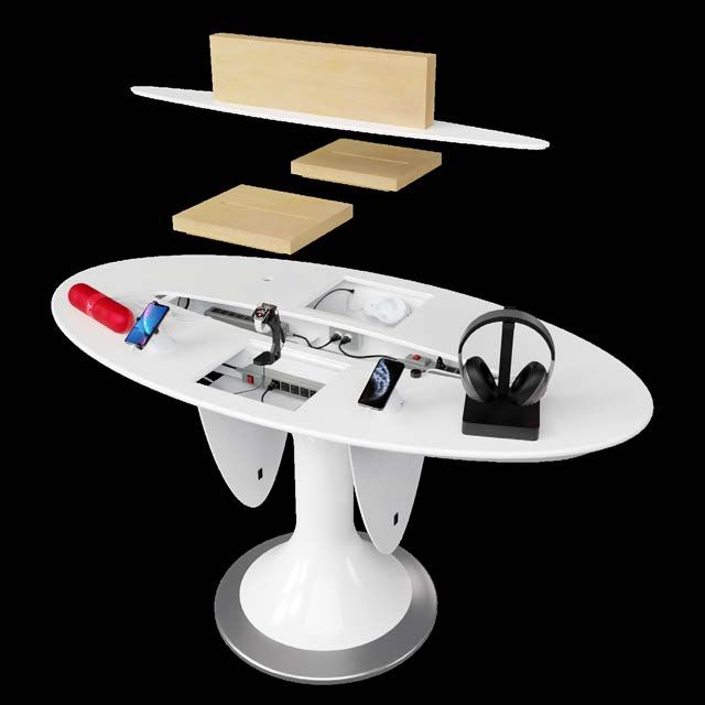
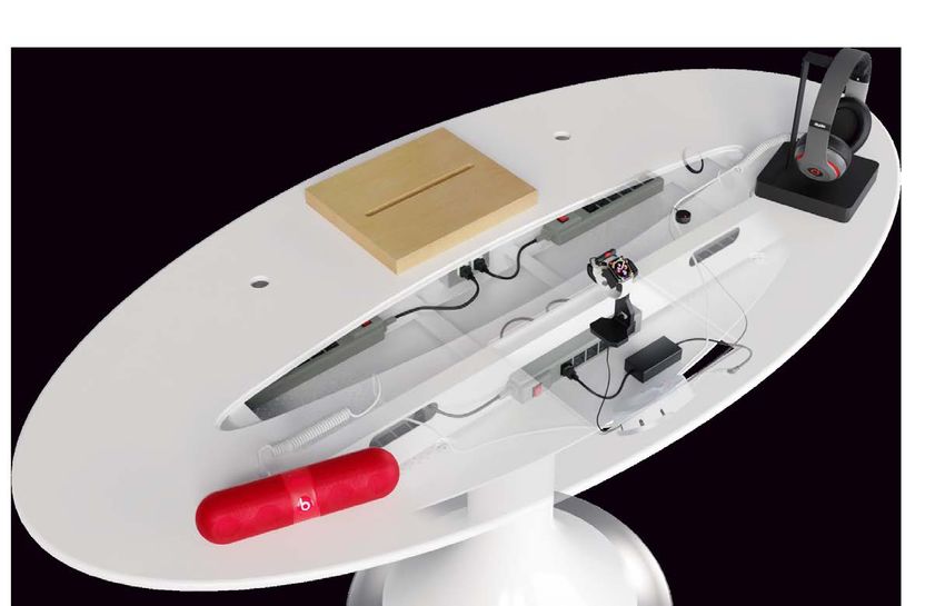
SMART FULL ZONE TABLE
                  EnCore | CR338 | Slim Wearable Sensor                                                                VP-1397W    K-CR338-02W    VZW-Wearable3

     CR338 - Phone & Tablet Security
                                                                                             CR338

                                                                                                                                        K-1140

                              CR338 positions will
                              adhere to the top
                              of the Smart Full
                              Zone Table.
                                                                                         For tables with the overlay, secure
             CR338                                                                       the CR338 using the K-1140 adapter
          Bottom View                                                                    mounting kit. This may already be                   Underside View
                                                                                         installed on the CR338.                              with Adapter

                                                                                                                              CR338
                                                                                                                            Side View

                                                                                                                INCORRECT                    CORRECT
                                                                           How to Remove Access Panels
                                                                           Lift and remove wood platter         Ensure the tamper switch is depressed
                                                                           and the center cover panels          and the power cord is properly aligned
                                                                           on top of the table.                 prior to securing the pedestal in place.
                                                                           Pull latch to open underside
                                                     Inside View           panels and push latch to close.

                                                                       EnCore - Accessory Security

                                                           The EnCore alarms can be                                         Ensure the tamper switch is
                                                           placed in the recess underneath                                  depressed prior to securing
                                                           the wooden blocks on either                                      the EnCore in place.
                                                           side of the table.

                                                                                                               EnCore
                                                                                                             Bottom View

  Back to Table of Contents                                                                                                                                   1
Rev. 09/01/2021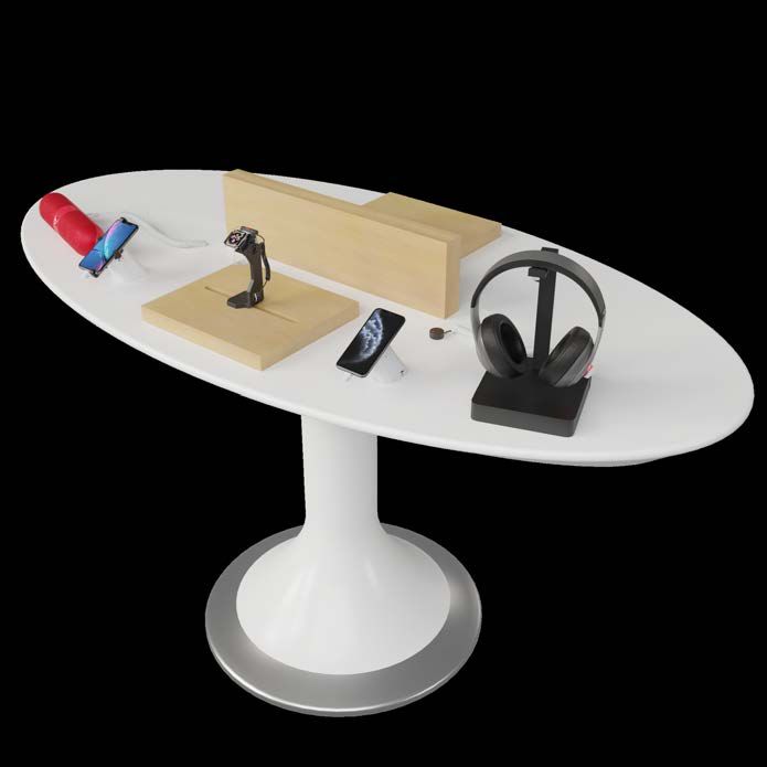
SMART FULL ZONE TABLE
                  EnCore | CR338 | Slim Wearable Sensor                                                   VP-1397W   K-CR338-02W   VZW-Wearable3

       Sensors - Accessory Security                                IR Extender Cable (KF-1102) - Accessory Security
       Sensors can be routed to the center of the fixture          The IR extender cable is used to extend                            IR Extender
                                                                                                                                        KF-1102
       and out through the mouse holes in the center               the EnCore receiver.
       cover. For accessories displayed on the wood
       blocks, sensors can be routed directly up through           Feed the cable up through the fixture
       the slot in the block.                                      slot and adhere the dome to the top
                                                                   shelf close to the edge of the slot.
       Micro-USB, Type-C, and X-Sensors feed up
       through the fixture and plug in, or adhere to               When it’s plugged in, you will see a
       products.                                                   green light illuminated on the dome.

       Up to 5 sensors are used with the EnCore.                   To arm and disarm the EnCore alarm,
       Typically, you will not use all 5.                          point the IR keyfob at the dome.

                                                     Mouse Holes

           X-Sensor        Type-C        Micro USB
          VP-1350WXL      VP-1439W      VP-1349WXL

                                                                                                               Power Supply
                              Full Zone Table
                              with Overlay
                                                                                                               The power cable drops
                                                                                                               through the hole and rounds
                                                                                                               into the ‘trap door’ on the
                                                                                                               bottom of the table.

  Back to Table of Contents                                                                                                                     2
Rev. 09/01/2021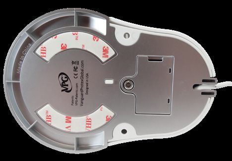
ENCORE                                                                                                                      click or scan QR code
Installation                                                                                                                   for installation video

   1       Tools & Parts Needed                               2     Remove the cover of the EnCore            3
                                                                    (VP-1397) with the V-T900 security
                                                                    driver or V-900-T Allen wrench.
                  VP-1397W                        V-T900                                                      Remove the 3M
                                                              Set the security                                adhesive liner.
                                                  or
                                                              code by changing                     or
                                                  V-900-T     the DIP switch
                  VP-1439W                                                                                    Clean the fixture
                                                              inside the EnCore.
                  or                                                                                          surface. Then,
                                                  V-37                                                        adhere the EnCore
                  VP-1349WXL                                                                                  to the fixture. Hold
                                                                         Switch #8 changes
                                                                                                              in place for 30
                  or                                                     the sensor LEDs to red.
                                                  KF-1102                                                     seconds.
                  VP-1350WXL
                                                                                                              Plug the
                  or                              KF-1106                                                     appropriate VPG
                  VP-1626                                                                                     accessory sensors
                                                  VP-1524C    IMPORTANT: The code must match the              into the Encore.
                                                              switches inside the IR Keyfob.

   4         Plug the IR Receiver cable into the              5                                               6    Plug the V-37 power supply into the
             back port of the EnCore.                                                                              EnCore’s power connector

                              Adhere the IR dome close
                               to the edge of the fixture
                                 slot. The IR Receiver will
                                  accept the keyfob’s IR
                                                                                                              Point the IR Keyfob at the IR
                                   signal for the EnCore.
                                                              Thread the sensor cables through the            Reciever and press the red
                              Reinstall the EnCore cover.     fixture. Install the sensors to the products.   lock button to arm the EnCore

  Back to Table of Contents                                                                                                                              3
Rev. 09/01/2021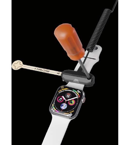
CR338                                                                                                                                   click or scan QR code
Installation | Smart Full Zone Table                                                                                                       for installation video

   1              Tools & Parts Needed           2    Make sure the tamper switch
                                                      is fully depressed and properly
                                                                                             3       ADHESIVE MOUNTING
                                                                                                   (for fixtures WITHOUT overlay)
                                                                                                                                    4            ADAPTER MOUNTING
                                                                                                                                               (for fixtures WITH overlay)
                                                      aligned before mounting.
                                                                                             Clean fixture surface and wipe dry.    IMPORTANT: This step & step 5A are
            VP-1751W                AD-238-8                                                 Remove the adhesive liner on the       necessary if the single hole adapter
                                                                                             base of the pedestal and adhere        is NOT already installed on the
                                                                                             the pedestal to the fixture.           CR338 pedestal.
            VP-1707W                AD-239-5                              Tamper Switch
                                                                                             Bottom View

            V-39                    AP-001-200

            KF-1106                 *K-1140                                                                                         Adhesive Tape

                  or              or                          Side View                                                             Adhesive Liner

   P-21012             P-21006         P-21002                                                                                        Fully remove both the adhesive liner
                                                  INCORRECT                 CORRECT          IMPORTANT: Hold for 30 seconds to        and the tape from the bottom of
  *Single Hole Adapter may come installed
                                                                                             ensure a strong bond.                    the pedestal.
  on pedestal.

   5               ADAPTER MOUNTING              6     Clean the back of the                 7    Attach the sensor to the          8
                  (for fixtures WITH overlay)          device with an alcohol pad                 pedestal by twisting the boot
                                                       and wipe dry.                              into the sensor.
   A. Thread the pedestal power cord
   through the adapter and screw to
   the bottom                                                   Plug the power
   of the pedestal.                                             coupler into sensor
                                                                                                                                    Plug the power
                                                                and device.
                                                                *if coupler is not plugged
                                                                                                                                    supply into the         Arm the system
                                                                in, system will not alarm.                                          pedestal and            by pressing the
                                                                                                                                    into an AC              red “lock” button
                                                                Remove adhesive                                                     outlet.                 on the IR Keyfob
                                                                liner on sensor and                                                                         (KF-1106). Point
                                                                adhere to the center                                                                        the keyfob near
                                                                of the device.                                                                              the black receiver
                                                                                                                                                            above the LED.
    B. Place
    connected
    pedestal and                                 IMPORTANT: If you are securing a                                                   System is on battery only if LED is
    adapter through the hole in the              glass back device, see page 8 prior                                                flashing quickly. Must have power
    fixture and tighten nut.                     to adhering sensor.                                                                plugged in to arm the system.

  Back to Table of Contents                                                                                                                                                  4
Rev. 09/01/2021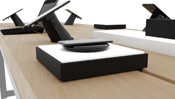
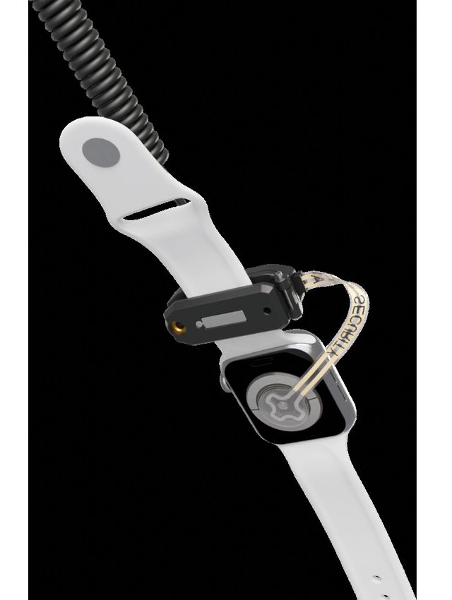
SLIM WEARABLE SENSOR                                                                                                click or scan QR code
Installation                                                                                                           for installation video

  1        Tools & Parts Needed                                             2     Thread the watch charger through the stand as shown.
                                      Cradles
                                      VP-1635
                                                                 V-T900
                  Stands              Samsung
                                       or
                  VP-1625             VP-1656                    V-T99
                  Generic
                                      Garmin
                                       or
                  or                                             V-37
                                      VP-1657
                                      Generic
                  VP-1559              or
                  Apple               VP-1664                    VP-1626
                                      Galaxy Active
                                       or
                                      VP-1689                    VP-1636
                  Alarms              Mont Blanc                                                                           Side View
                                       or
                  VP-1397W                                       VP-1433M
                                      VP-1694
                                      Gizmo

  3          Insert the watch stand into the bottom of the black Wearable   4
             Riser box. Thread the watch sensor cable through the watch
             stand and riser as shown.                                                                                           Bottom View

                                                           Bottom View

                                                                            Install the Wearable Riser’s base plate with the 4 Phillips head screws.

  Back to Table of Contents                                                                                                                            5
Rev. 09/01/2021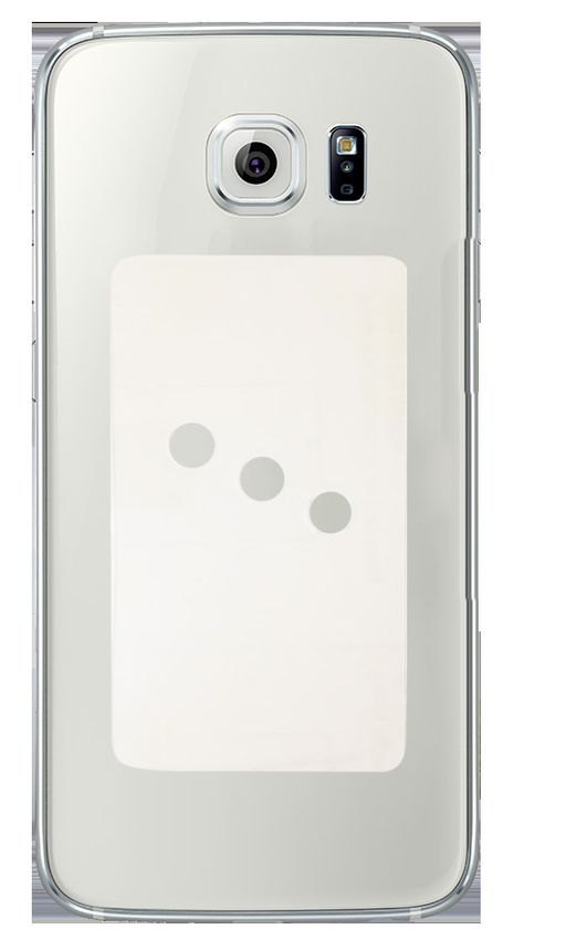
SLIM WEARABLE SENSOR                                                                                              click or scan QR code
Installation                                                                                                         for installation video

  5          Use the appropriate watch cradle for
             the product you wish to secure.
                                                    6     Insert the provided binding screw into
                                                          the watch cradle.
                                                                                                   7
                                                                                                   Loosen the screw
                                                                                                   on the top of the
                                                                                                   Slim Wearable
                                                                                                   Sensor (VP-1626)
                                                                                                   and remove the
                                                                                                   clear shunt plug
                                                                                                   on the side of the
                                                                                                   sensor.

                                                                                                   Insert the Flex Sensor
                                                                                                   (VP-1636) into the
   Apply the circular adhesive to the back of                                                      sensor.
   the watch puck. Thread the watch charging
   cable through the watch cradle for the           Screw the watch cradle to the watch stand
   specified device. Remove adhesive liner and      with the security driver
   adhere the charging puck inside the cradle.      (V-T900).

  8                                                 9                                              10                  For the Apple Watch Cradle,
                                                                                                                 remove the rubber padding if using
                                                                                                                    a 42mm Apple Watch or larger.

                                                    Remove adhesive liner
                                                    and adhere the Flex
                                                    Sensor to the back of
                                                    the watch head.
   Close the Slim Wearable                          Ensure the Flex Sensor will
                                                                                                                 Rest the watch on the stand,
   Sensor onto the top watch                        not be crimped when the
                                                                                                                 and plug the sensor into the
   band and tighten with the                        watch is placed on the
                                                                                                                 EnCore alarm unit (VP-1397).
   security driver.                                 display stand or fixture.
                                                                                                   IMPORTANT: If the Flex Sensor is damaged
                                                                                                   or missing, do NOT plug sensor into EnCore.

  Back to Table of Contents                                                                                                                           6
Rev. 09/01/2021
DEVICES WITH INDUCTIVE CHARGING/CAMERAS
Accessory Security

                              X-Sensors

                              X-Sensors will be used on phones that use inductive
                              charging. No flex cover is necessary.

                              If the phone has a removable back, detachable
                              parts or pieces, or the battery can be removed, you
                              will need to use a secondary X-Sensor to fully secure it.

                              Thread the X-Sensor up through the slot in the table,
                              and adhere it near the top of the phone, clearing the
                              camera and other important features of the device.

                              Speakers & Other Devices w/EnCore

                              Speakers use a Type-C input for powering the device.

                              Use a VPG power and security Type-C sensor
                              plugged into the side of the device as shown.

                              The EnCore lights on the sensor will light up a steady
                              red when the product is secure.

                              Type-C Power & Security Sensors

                              Type-C PAS sensors are able to charge and secure
                              devices at the same time.

                              When applicable, use the retainer bracket that
                              comes with the sensor. These sensors work with the
                              EnCore, but remember, the EnCore is not designed
                              to charge phones.

                              Charge pads, speakers, and other small accessories
                              are perfect for the Type-C PAS plugged into an
                              EnCore alarm.

  Back to Table of Contents                                                               7
Rev. 09/01/2021
ADHESIVE RESISTANT DEVICES
Merchandising Requirements | All Glass Back Phones

              AD-218 - Clear Adhesive

              Any device that has a glass back requires the AD-218 to
              make sure VPG sensors properly adhere to the product.

              1) Clean the back of the device with an alcohol pad
                  and wipe dry immediately.

              2) Remove the adhesive liner from the AD-218.

              3) Adhere the AD-218 to the back of the device.

              4) IMPORTANT: Ensure the tamper switch on the CR338
                 sensor aligns with one of the 3 holes on the AD-218
                 adhesives.

              Note: Heat (whether it be ambient or from the device)
              plays a major role in the effectiveness of adhesives. For
              optimal adhesive bond, phones should be displayed in a
              cool, dry area.

  Back to Table of Contents                                               8
Rev. 09/01/2021
CR338 IMPORTANT: Do NOT try to pull up on the CR338 base. It can damage the
pedestal and/or the fixture. To remove a CR338 pedestal that’s adhered
Pedestal Removal to Verizon fixtures, follow the steps below.
click or scan QR code for video
1 Tools & Parts Needed 2 Disarm the system by pressing the 3
green “unlock” button on the IR
Keyfob (KF-1106).
KF-1106
VP-1446
VP-1477
or
V-44 Place the VP-1477 removal tool over
Use the magnet tool (VP-1446) to twist and the pedestal with the indentation side
release the boot from the sensor. facing up.
4 5 6
Optionally, you can use the V-44 removal Alternate pulling the removal tool handles
Gently twist the removal tool to break the tool. Wrap the removal tool’s cable with each hand, in a sawing motion, until
adhesive bond. underneath the pedestal. the pedestal is detached.
Back to Table of Contents 9
Rev. 09/01/2021IR KEYFOB (KF-1106)
Troubleshooting
Arming and Disarming
Arm
Use the red “lock” button to arm
the system, and the green “unlock”
Disarm button to disarm the system.
IMPORTANT: Ensure the button pads IR Emission
are not installed upside down.
Ensure you hold the keyfob in
the proper orientation.
The IR signal emits from the front
and front underside of the fob.
Range Point the keyfob at the IR lens on
the product.
You must be within 6”-12” of the IR receiver.
DIP Switches
Battery Check
Check to see if the
alarm’s DIP switches To check if the battery is dead, cup your
match by opening the hand around the keyfob, or go into a dark
IR keyfob. Compare room. Hold down one of the buttons and look
the DIP switch settings for a strobing red LED through the blue plastic
inside the keyfob with as shown.
the alarm you are
arming or disarming. IMPORTANT: Do NOT hold down the buttons
Pictured to the right is when attempting to arm or disarm. After
the EnCore. holding a button down for 5 seconds, the key
is programmed to stop emitting the IR signal
Note: CR338s do not have to have to avoid draining the battery. You must wait
matching DIP switch settings in order 10 seconds for it to reset.
for the keyfob to arm and disarm those
systems. Battery Life
Battery life varies depending on keyfob usage. In most use
cases, the keyfob battery (CR2032) can last at least 1 year.
Back to Table of Contents 10
Rev. 09/01/2021SPARE PARTS
Maintenance
CR338 Kit
Alarms
K-CR338-02W
CR338 Pedestal CR338 Sensor Mounting Kit Power Supply EnCore
VP-1751W VP-1707W K-1106 V-39 VP-1397
Power
PAS
Couplers
Micro USB PAS
PAS Bracket Clear PAS Bracket Type-C PAS Sensor Sensor Micro USB Coupler USB-C Coupler Lightning Coupler
VP-1431C-5 VP-1202C-5 VP-1439W VP-1349WXL P21002 P21006 P21012
Tools Power Supply
Sensor Removal 1/8” Allen Security 1/8” Allen Security Allen Security
Tool Screwdriver Screwdriver Wrench Magnet Tool Power Supply Power Supply
VP-1477 T-99 V-T900 V-41 VP-1446 V-37 V-39
Adhesives
CR338 Sensor
CR338 Adhesive Adhesive EnCore Adhesive X-Sensor Adhesive Glass Adhesive Primer Stick Alcohol Pads
AD-239-5 AD-238-8 AD-139-20 AD-131-50 AD-218-10 AD-105-5 AP-001-200
Misc.
IR Receiver IR Keyfob X-Sensor X-Sensor Cover Velcro Supply Bag
KF-1102 KF-1106 VP-1350WXL VP-1524C V-60V VPG Bank Bag
Generic Watch Garmin Watch
Cradle Cradle
*Cradle
Wearable Kit VP-1657 VP-1656
VZW-Wearable3
options for Samsung Watch Mont Blanc Watch
VP-1625 Cradle Cradle
Apple Watch Slim Wearable VP-1635 VP-1689
Wearable Stand Stand Sensor Flex Sensor Wearable Sensor Galaxy Active Gizmo Watch Cradle
VP-1625* VP-1559 VP-1626 VP-1636 VP-1433M VP-1664 VP-1694
Back to Table of Contents 11
Rev. 09/01/2021You can also read