The Complexity of Joint Regeneration: How an Advanced Implant Could Fail by Its In Vivo Proven Bone Component
←
→
Page content transcription
If your browser does not render page correctly, please read the page content below
Journal of Trial and Error 23 March, 2021 EMPIRICAL
https://doi.org/10.36850/e3 ROLLING ARTICLE

The Complexity of Joint Regeneration: How
an Advanced Implant Could Fail by Its In
Vivo Proven Bone Component
Paweena Diloksumpan1† , Florencia Abinzano2† , Mylène de Ruijter2 , Anneloes
Mensinga1,2 , Saskia Plomp1 , Ilyas Khan3 , Harold Brommer1 , Ineke Smit1 , Miguel
Dias Castilho2 , P. René van Weeren1 , Jos Malda1,2 , Riccardo Levato1,2

1 Department of Clinical Sciences, Faculty of
 Abstract
Veterinary Medicine, Utrecht University,
3584 CM, Utrecht, the Netherlands Articular cartilage damage is a major challenge in healthcare due to the lack of long-term
2 Department of Orthopaedics, University repair options. There are several promising regenerative implant-based approaches for the
Medical Center Utrecht, Utrecht University,
 treatment, but the fixation of the implant remains a significant challenge. This study evalu-
3584 CX, Utrecht, the Netherlands
3 Center for Nanohealth, Institute of Life ated the potential for repair of an osteochondral implant produced through a novel combined
Science, College of Medicine, Swansea bioprinting-based chondral-bone integration, with and without cells, in an equine model. Im-
University, SA2 8PP, Swansea, UK
†Paweena Diloksumpan and Florencia
 plants consisted of a melt electrowritten polycaprolactone (PCL) framework for the chondral
Abinzano contributed equally to this work. compartment, which was firmly integrated with a bone anchor. The bone anchor was pro-
Correspondence: Riccardo Levato, duced by extrusion-based printing of a low-temperature setting bioceramic material that had
Department of Orthopaedics, University
Medical Center Utrecht, Utrecht University,
 been proven to be effective for osteo-regeneration in an orthotopic, non-load bearing and
3584 CX, Utrecht, the Netherlands non-articular site in the same species in an earlier in vivo study. Articular cartilage-derived
Email: R.Levato-2@umcutrecht.nl progenitor cells were seeded into the PCL framework and cultured for 28 days in vitro in the
Companion Piece: This paper has an presence of bone morphogenetic protein-9 (BMP-9), resulting in the formation of abundant
accompanying reflection piece,
Nederbragt, H., (2021). Ponies, Joints,
 extracellular matrix rich in glycosaminoglycans (GAGs) and type II collagen. The constructs
Complexity and the Method of Indifference. were implanted in the stifle joints of Shetland ponies with cell-free scaffolds as controls. Clin-
Read the abstract at the end of this article.
 ical signs were monitored, and progression of healing was observed non-invasively through
 radiographic examinations and quantitative gait analysis. Biochemical and histological anal-
 yses 6 months after implantation revealed minimal deposition of GAGs and type II collagen in
 the chondral compartment of the defect site for both types of implants. Quantitative micro-
 computed tomography showed collapse of the bone anchor with low volume of mineralized
 neo-bone formation in both groups. Histology confirmed that the PCL framework within the
 chondral compartment was still present. It was concluded that the collapse of the osteal an-
 chor, resulting in loss of the mechanical support of the chondral compartment, strongly af-
 fected overall outcome, precluding evaluation of the influence of BMP-9 stimulated cells on
 in vivo cartilage regeneration.

 KEYWORDS
 cartilage, 3D (bio)printing, equine model, osteochondral, articular cartilage-derived progenitor cells

Take home message bone morphogenetic protein-9 (BMP-9) stimulated progenitor cells. Collapse
The collapse of the osteal anchor of these osteochondral implants affected the occurred because bone regeneration competent materials, which had shown
integration of the construct with the native tissue and seriously compromised success in a different anatomical location, were unable to correctly anchor the
the mechanical stability. This precluded drawing firm conclusions about the implant in the complex biomechanical environment of the joint. The imperfect
potential for in vivo cartilage repair of the chondral compartment, consisting of dimensional match, originating from the intrinsic variability of the 3D printing

Received: 15 April, 2020, Accepted: 11 March, 2021, Published Online: 23 March, 2021 https://www.jtrialerror.com 1
2 EMPIRICAL DILOKSUMPAN ET AL.

process, had a much bigger influence than in previous studies. When combined Another major challenge is the connection between the osteal and chondral
with the brittle nature of the material, the implant was unable to withstand the compartments of the tissue-engineered osteochondral graft when using cell-
complex loading of the knee joint. friendly materials of strongly different mechanical characteristics. Recently, a
 technique for attaching the chondral compartment to the osteal compartment
Purpose using melt electrowriting (MEW) was developed (Diloksumpan, de Ruijter,
The current study aimed at evaluating a cell-laden and a cell-free version of an et al., 2020), in which MEW fibers of the chondral compartment were partially
osteochondral composite scaffold for cartilage repair that consisted of an in incorporated into the slowly setting apatite-based osteal compartment, thereby
vivo proven osteogenic bone scaffold for the osteal compartment and made use binding the two compartments together. This strategy allows both for optimiz-
of a novel interface for the connection of the chondral and osteal compartments. ing the mechnical properties of the MEW-reinforced chondral compartment,
 and for integrating the chondral and osteal compartments.
Introduction Regarding the seeding of regeneration-competent cells within the chondral
Focal cartilage damage is a major challenge in human healthcare since it compartment, articular cartilage-derived progenitor cells have been recently
leads to an increased risk of developing early osteoarthritis (Kloppenburg & identified and characterized in both humans and horses as a distinct cell popula-
Berenbaum, 2020). Most of the available repair approaches are palliative with tion that has the potential for cartilage repair (McCarthy et al., 2012; Williams
limited alleviation time, generating fibrous tissue with reduced mechanical et al., 2010). This potential was further shown to be retained in combination
strength (Kwon et al., 2019). There are no effective treatments that can fully with biomaterials (Frisbie et al., 2015; Levato et al., 2017), making this cell
restore the anatomical structure and function of focal cartilage defects. This type a promising candidate for a comprehensive regenerative approach. Addi-
unmet clinical need drives the ongoing quest for regenerative medicine and tionally, it was recently discovered that supplementation with BMP-9 during in
tissue-engineering approaches for articular cartilage repair (Malda et al., 2019). vitro culture of ACPCs resulted in higher expression of gene-markers related
 Many new promising technologies (Johnstone et al., 2019; Patel et al., with hyaline-like extracellular matrix production, compared to supplementation
2019) are currently being developed and tested with the aim of finding an with transforming growth factor (TGF ), a more commonly used growth factor
implant that is effective in facilitating regeneration of cartilage. Given the in cartilage tissue engineering (Morgan et al., 2020). This observation sparked
difficulties associated with the fixation of chondral constructs in the joint interest in further investigation of the potential of BMP-9-stimulated ACPCs
(Gotterbarm et al., 2008; Mancini et al., 2017), an alternative approach is for cartilage repair in vivo.
the use of composite osteochondral constructs composed of distinct osteal The current study aimed at evaluating an osteochondral composite scaffold
and chondral compartments that can be surgically press-fitted into suitably for cartilage repair. These constructs were composed of a combination of a
prepared defects, thereby avoiding the risk of dislodgement (Martin et al., 2007). previously proven osteogenic CDHA 3D printed scaffold for the osteal compart-
However, the latter approach still faces many challenges, including design and ment, onto which a chondral compartment composed by MEW micro-fibrous
optimization of the osteal compartment to act as an anchor for the overlying meshes is tightly anchored. For the chondral compartment, an experimental
chondral compartment, production of a firm and durable connection between group in which the MEW structure was seeded with ACPCs that had been
osteal and chondral compartment (Boushell et al., 2017), and optimization stimulated for 28 days with BMP-9 before implantation (Abinzano et al., 2018),
of the composition and structure of the chondral compartment (Diekman & was compared with an implant featuring a non-filled, cell-free MEW cartilage
Guilak, 2013; Lee et al., 2014). scaffold as control. It was hypothesized that 1) the CDHA scaffold would
 To address those challenges, biomaterials that hold the potential for facilitat- show comparable performance in the horse when implanted in the subchondral
ing osteoregeneration within the osteal compartment were recently developed bone as in the tuber coxae in terms of firmly anchoring in the surrounding
and investigated. First, 3D printed brushite-based scaffolds have been shown to tissue and inducing bone growth; 2) the novel interface would provide a lasting
be effective in promoting new bone growth after 6 months in an equine model connection between the osteal and chondral compartments of osteochondral
that used the tuber coxae as implantation site (R. A. Vindas Bolaños et al., graft; and 3) the engineered chondral compartment of the osteochondral graft
2020). However, these materials are usually processed using aggressive acidic containing the stimulated ACPCs would outperform the cell-free structures in
treatments, precluding the direct incorporation of cells and/or some types of terms of in vivo cartilage matrix production (specifically, amount and density
polymer during the fabrication phase. Therefore, an apatite-based scaffold that of type II collagen and GAGs, with resulting mechanical properties as close as
could harden under physiological conditions into a calcium-deficient hydroxya- possible to those of native, healthy cartilage).
patite (CDHA) was developed. This material had been shown to be effective in
a 7-month long in vivo study, upon implantation in a critical size defect in the Materials and Methods
tuber coxae of horses. That study was performed to compare two sophisticated Experimental design
architectures with constant and gradient pore size, respectively. The material To assess the performance of integrated 3D printed osteochondral grafts that
was shown to facilitate excellent new bone formation, particularly when using contained a cell-laden or a cell-free chondral compartment, the constructs
the scaffold with constant pore size (Diloksumpan, Vindas Bolaños, et al., were orthotopically implanted in a large animal model. Eight Shetland ponies
2020). This showed the potential for using such material as an osteal anchor of (female, age 4 − 12 years, weight 149 − 217 (166 ± 29 )) were used and
a tissue-engineered osteochondral graft. samples were implanted in the medial femoral ridge in the stifle joints. Healing

View interactive version here. Journal of Trial and Error 2021
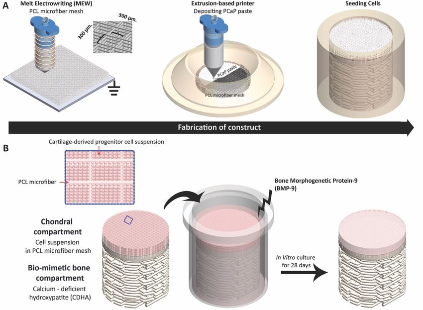
DILOKSUMPAN ET AL. EMPIRICAL 3

FIGURE 1 Flow chart representing timeline of the experiment including health monitoring at each phase of the experiment.

was monitored for 6 months, after which the animals were humanely euthanized. filter (Millex®-GS). This paste was loaded to a cartridge and kept at 4°C until
The study was approved by the ethical and animal welfare body of the Utrecht use.
University (Approval nr. AVD108002015307 WP23). Osteochondral constructs were produced by combining the PCL microfiber
 Ponies were housed in individual boxes and fed a limited ration of concen- mesh and the PCaP paste to form the reinforcement of the chondral compart-
trates together with hay for maintenance and free access to water. Quantitative ment and the biomimetic bone compartment, respectively. Fabrication was
gait analysis and radiographic examination of the stifle joints were performed performed by directly depositing the PCaP paste (approximated strand diam-
before surgery for baseline values. Post-operatively, the animals were kept eter = 250 ) onto the hydrolyzed MEW mesh (Figure 2). Eighty percent
stabled for 6 weeks with daily monitoring of vital signs, lameness checks at of the mesh thickness was set as the initial height for depositing the first of
walk, and examination of the operated joints for swelling or other signs of non-macroporous PCaP layer, as this proved to be the height that did not dam-
inflammation. In week 5 and 6, they were hand-walked for 10 minutes twice age the mesh structure and ensured an optimal integration between the bone
daily and from week 7 on, they were kept at pasture. Quantitative gait analysis compartment and the chondral compartment. The first two layers of PCaP
and radiographic exams were performed at 3 weeks, 3 months, and 6 months were deposited without macro-spacing, to mimic the subchondral bone plate,
post-operatively. After 6 months, ponies were humanely euthanized for har- and followed by layers with designed macro-spacing of 700 to mimic the
vesting samples for both quantitative and qualitative analyses. The timeline of cancellous bone section (diameter = 6 , height = 5 ).
the experiment is represented in Figure 1. After finishing the fabrication process, the osteochondral constructs were
 allowed to set at 37°C under saturated relative humidity to form a solid,
 Fabrication of construct biomimetic bone compartment through conversion of the PCaP composite to
Microfiber meshes were produced from medical-grade PCL (Purasorb® PC 12 CDHA. Finally, the osteochondral constructs were disinfected in 70% ethanol
Corbion PURAC, The Netherlands) by using MEW technology as previously and exposed to UV-light for 1 hour, prior to seeding of cells.
described (de Ruijter et al., 2019). The meshes were produced by horizontally
patterning the microfiber (diameter = 10 ) to form continuously uniform In Vitro pre-culture
square spacing (300 300 ) and vertically stacking the same pattern until Allogeneic articular cartilage progenitor cells (ACPCs) were obtained as pre-
reaching 1300 in total thickness. This structure was achieved by printing viously described (Levato et al., 2017; Williams et al., 2010) from animals
with a temperature of 90°C, a pressure of 1.25 bar, voltage of 10 kV, and collec- that were euthanized at the Utrecht University Veterinary Hospital for causes
tor velocity of 15 ⋅ −1 . Additionally, printing was performed at ambient unrelated to disease or impairment of the musculoskeletal system and whose
temperature (22 − 24°C) with a humidity between 30 − 50%. Subsequently, remains were donated for research purposes. Briefly, hyaline cartilage was
PCL microfiber meshes were hydrolyzed by soaking them in sodium hydroxide collected in a sterile fashion, minced, and digested at 37°C with 0.2% ⋅ −1
(1M NaOH) for 15 minutes and washed in Milli Q water for 10 minutes 4 times. pronase solution for 2 hours, followed by 12 hours in 0.075% ⋅ −1 collagenase
Finally, sterilization was carried out by immersion of the mesh in 70% ethanol solution. ACPCs were then selected using a fibronectin adhesion assay (Levato
for 15 minutes, followed by air-drying in a sterile cabinet until use. et al., 2017). Cells were expanded in culture and stored in liquid nitrogen until
 Printable calcium phosphate (PCaP) paste was prepared as earlier described further use. After thawing, cells were expanded until passage 3 prior to their
(Diloksumpan, de Ruijter, et al., 2020). In short, 2.2 ⋅ −1 of alpha-tri use for the experiment.
calcium phosphate ( -TCP, average particle size = 3.83 , Cambioceramics, The constructs made of the combined CDHA and MEW meshes were dis-
Leiden, the Netherlands) and 0.13 ⋅ −1 of nano-hydroxyapatite (nano-HA, infected in ethanol and exposed to UV-light for 1 hour as mentioned above.
particle size = 200 , Ca5 (OH)(PO4 )3 , Sigma-Aldrich) were mixed with To avoid any pH changes that might affect the cells, the constructs were sub-
40% ⋅ −1 poloxamer solution (Pluronic® F-127, Sigma-Aldrich). -TCP sequently washed 3 times for 10 minutes with PBS and then immersed for 1
and nano-HA powder were disinfected with UV-light for 1 hour before mixing. week in cell culture medium consisting of Dulbecco’s Modified Eagle Medi-
The poloxamer solution was disinfected by filtration through a 0.22 sterile um/Nutrient Mixture F-12 (DMEM/F-12, 11320033, Gibco, The Netherlands)

Journal of Trial and Error 2021 View interactive version here.
4 EMPIRICAL DILOKSUMPAN ET AL.

F I G U R E 2 Schematic picture representing the fabrication process of the tissue engineered osteochondral constructs. Fabrication techniques and
processes for forming osteochondral graft (A), Material composition of osteochondral graft and process during in vitro preculture (B).

supplemented with 10% ⋅ −1 heat-inactivated fetal calf serum (FCS, Gibco, 10 − 15 ⋅ −1 ) were administered pre-operatively as analgesic medication
The Netherlands), 0.2 L-ascorbic acid 2-phosphate (Sigma), 1% MEM and antibacterial preventative therapy, respectively.
Non-Essential Amino Acids Solution (11140035, Gibco, The Netherlands) and The medial femoral ridge of the stifle joint was exposed by arthrotomy
100 ⋅ −1 penicillin with 100 ⋅ −1 streptomycin (Life Technologies, and an osteochondral lesion (diameter = 6 , depth = 6 ) was surgically
The Netherlands). Media were refreshed every 2-3 days. created using a power drill. The surgical area was flushed by saline for cooling
 On the day of seeding, medium was refreshed 2 hours before seeding and and removal of debris. Cell-laden constructs were implanted press-fit in a
scaffolds were placed inside a custom-made polydimethylsiloxane (PDMS) randomly chosen hind limb, with the cell-free control being implanted in the
ring (Figure 2) that prevented overflow of the cell suspension from the cartilage contralateral limb. After closing the arthrotomy wound in four layers in routine
compartment to the bone scaffold. Ten million cells were suspended in 100 fashion, procaine penicillin was administered (Procapen, intramuscular (IM),
of medium and seeded on top of the constructs. The cell suspension was left 20 ⋅ −1 ). Post-operatively, nonsteroidal anti-inflammatory medication
to settle at the bottom of the cartilage part for 30 minutes. Afterwards, 2 (metacam, per os (PO), SID, 0.6 ⋅ −1 ) was administered for 5 days and
of cartilage medium supplemented with 100 ⋅ −1 of BMP-9 (PeproTech, opioids (tramadol, PO, BID, 5 ⋅ -1 ) were administered for 2 days.
The Netherlands) was carefully added to the well. The seeded constructs were
cultured for 4 weeks prior to implantation, refreshing the medium 3 times a Gait analysis
week. The ponies were trained on a treadmill prior to the study using a standard
 protocol for treadmill habituation. Twenty-eight spherical reflective markers
 Surgical procedure with a diameter of 24 (topline) and 19 (elsewhere) were attached with
Ponies were premedicated with detomidine (intravenous (IV), 10 ⋅ −1 ) and double-sided tape and second glue to anatomical landmarks (Figure 3). Kine-
morphine (IV, 0.1 ⋅ −1 ) and anesthesia was induced with midazolam (IV, matic data were collected on a treadmill (Mustang, Fahrwangen, Switzerland)
0.06 ⋅ −1 ) and ketamine (IV, 2.2 ⋅ −1 ). Anesthesia was maintained at trot using six infrared optical motion capture cameras (ProReflex, Qualisys,
with isoflurane in oxygen together with continuous rate infusion of detomidine Gothenburg, Sweden) recording at a frame rate of 200 for 30 seconds at
(IV, 10 ⋅ −1 /h) and ketamine (IV, 0.5 ⋅ −1 /h). Meloxicam (IV, 0.6 ⋅ each session to obtain a sufficient number of strides.
 −1 ), morphine (epidural injection, 0.1 − 0.2 ⋅ −1 ) and ampicillin (IV, To process the data, the reconstruction of three-dimensional coordinates

View interactive version here. Journal of Trial and Error 2021
DILOKSUMPAN ET AL. EMPIRICAL 5

 and for collecting tissue from the chondral compartment of the implant for
 biochemical analyses. After this, all tissues were fixed in 4% formaldehyde for
 subsequent histological processing.

 Biomechanical evaluation
 The compressive properties of the chondral compartment of the defect site,
 the adjacent surrounding native cartilage and the more distant surrounding
 native cartilage (5 − 10 from the boundary of the defect) ( = 7 for cell-
 laden constructs and = 7 for cell-free constructs) were evaluated with a
 dynamic mechanical analyzer (DMA, DMA Q800, TA instrument) equipped
 with a custom-size compressing probe (diameter = 2 ). A ramp force of
 0.250 ⋅ −1 was applied until reaching 2.0 , to limit the deformation of
 sample to values below 200 . Compression modulus was calculated as the
 slope of the stress-strain curve in the range between 10 − 12% strain.

 Biochemical evaluation
F I G U R E 3 Schematic picture representing location of the markers for Firstly, biochemical analyses were performed on supplemental pre-implantation
gait analysis. constructs ( = 3) that had been prepared in the same batch as the constructs
 that were later implanted. The chondral compartments of 28-day cultured
 constructs were removed and freeze-dried. Next, dry samples were digested in
of each marker was automatically calculated by Q-Track software (Qtrack,
 papain (Sigma Aldrich) at 60°C overnight. DNA, sulphated glycosaminoglycan
Qualisys, Gothenburg, Sweden). Each marker was identified and labelled
 (sGAG), and alkaline phosphatase (ALP) content were quantified by perform-
using an automated model (AIM model) and manual tracking. Raw data of
 ing the Quan-iT-Picogreen-dsDNA-kit assay (Molecular Probes, Invitrogen,
the designated markers were exported to Matlab (version 2018a, Niantics,
 Carlsbad, USA), the dimethylmethylene blue assay (DMMB, Sigma-Aldrich,
California) for further analysis using custom written scripts. For each stride,
 The Netherlands) and the p-nitrophenyl phosphate assay (SIGMAFAST™,
two symmetry parameters were calculated using the vertical displacement of
 Sigma-Aldrich), respectively.
the head and pelvis (tubera sacrale) markers. For each stride, the differences
 Secondly, tissue fractions that were collected from the chondral compart-
between the two vertical displacement minima of the head (MinDiffhead) and
 ments of harvested implants ( = 6 for cell-laden constructs, = 7 for
pelvis (MinDiffpelvis) were calculated. Using the markers, limb-segments
 cell-free constructs) were kept at −80°C, followed by lyophilization. Colla-
were formed and angles between these limb-segments were calculated. The
 gen content was quantified using an hydroxyproline assay (L-Hydroxyproline,
difference between the maximal and minimal angle was defined as the range
 Merck KGaA), and the sGAG and DNA quantification was performed as de-
of motion (ROM) of a joint. For each timepoint, the mean value of all strides
 scribed above.
for each parameter was calculated.

 Radiographic examination Microcomputed tomography
 Microcomputed tomography was employed for the quantitative analysis of
Stifles were radiographed in 3 projections: lateromedial, craniolateral-
 the bone compartments from the harvested osteochondral lesions ( = 7
caudomedial oblique and caudo-cranial projection using standard machine
 for cell-laden constructs, = 7 for cell-free constructs). Six freshly made
settings before surgery (baseline), at 3 weeks postoperatively and at 6 months,
 osteochondral grafts were scanned in a micro-CT scanner (Quantum FX-Perkin
just before euthanasia.
 Elmer) to quantify the initial volume of PCaP material, pre-operatively. The

 Euthanasia and sample harvest post-mortem harvested tissue containing the defect area and the surround-

After 6 months, animals were euthanized by induction with Midazolam (IV, ing native tissue were similarly scanned (voltage = 90 , current = 200 ,

0.06 ⋅ -1 body weight) with ketamine IV, (2.2 ⋅ −1 body weight) voxel size = 30 3 and total scanning time = 3 ). Subsequently, the

and subsequent administration of sodium pentobarbital (IV, 1400 ⋅ −1 3D-reconstructed images were processed and analyzed using image J soft-

body weight). Next, the stifle joint was exposed, and gross assessment of the ware (Schindelin et al., 2012) and Bone J plugin (Doube et al., 2010). Two-

medial trochlear ridge was performed, focusing on the degree of filling of the dimensional regions of interest (ROIs) were selected in an axial plane at the

defect, the integration of repair tissue with the surrounding native tissue and boundary between the defect and the surrounding native tissue and interpo-

the surface quality of the repair tissue. Subsequently, the entire osteochondral lated to form a three-dimensional volume of interest (VOI). Thresholding was

area containing the constructs was harvested for further analyses with the aid of performed to separately select areas of ceramics and newly formed bone re-

a surgical bone saw. Harvested tissues were initially kept in sterilized PBS for spectively for further calculation. Then, the percentages of mineralized newly

micro-computed tomography (micro-CT) scanning, biomechanical analyses formed bone, of non-mineralized tissue and of remaining ceramics, including
 the percentage of ceramics volume loss, were quantified.

Journal of Trial and Error 2021 View interactive version here.
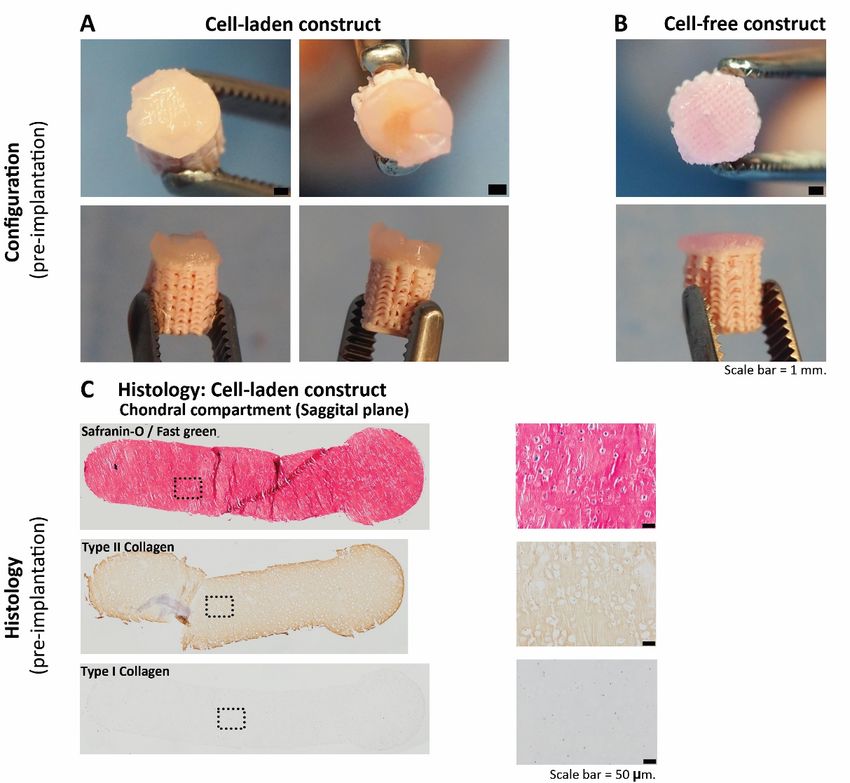
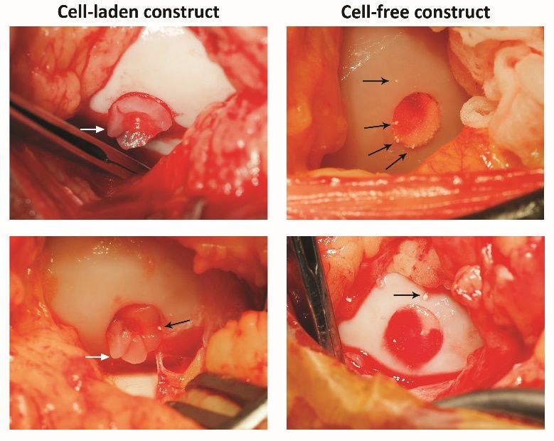
6 EMPIRICAL DILOKSUMPAN ET AL.

 Histological evaluation
Firstly, supplemental pre-implantation constructs ( = 3) that had been pre-
pared in the same batch as the ones that later were implanted were fixed in
4% formaldehyde. After decalcification in 0.5 Ethylenediaminetetraacetic
acid (EDTA) disodium salt ( = 8) for 1 day, tissues were dehydrated with
graded ethanol series, cleared in xylene, and embedded in paraffin. Paraffin
embedded tissues were sliced to 5 sections. Histochemical evaluation of
GAG was done by safranin-O / fast green staining. Type I collagen (primary
antibody: monoclonal antibody EPR7785, 1.083 ⋅ −1 , Abcam) and type
II collagen (primary antibody: monoclonal antibody II-II6B3, 0.06 ⋅ −1 ,
DSHB) were visualized by immunohistochemistry.
 The tissues that were harvested after 6 months ( = 7 for cell-laden con-
structs, = 7 for cell-free constructs) were kept in 4% formaldehyde and then
decalcified in 0.5 EDTA disodium salt ( = 8) for 24 weeks. Decalcified
tissues were cut into two halves before processing to enable visual inspection
of the center of the lesion. Tissues were dehydrated with graded ethanol series,
cleared in xylene and finally embedded in paraffin. Paraffin embedded tissues
were sliced to 5 sections. For assessment of morphology and cell distribu-
 F I G U R E 4 Representative pictures of cell-laden and cell-free
tion, hematoxylin-eosin staining (Mayer’s haematoxylin, Merck 109249 and osteochondral constructs at the time of implantation. Cell-laden (A) and
eosin, Merck 115935) was performed. GAG and collagen alignment were cell-free constructs (B) at the time of implantation. Positive safranin-O
assessed after safranin-O / fast green and picrosirius red staining, respectively. staining indicating the presence of glycosaminoglycans (pink = positive),
Types I collagen and type II collagen were visualized by immunohistochem- positive type II collagen (brown = positive) and negative type I collagen
 (brown = positive) immunohistochemistry were observed in the chondral
istry, as described above. For immunohistochemistry, all samples were treated
 compartment of the cell-laden constructs before implantation (C).
according to previously published protocols (Levato et al., 2017). Stained
histological slides were imaged using a light microscope (Olympus BX51,
Olympus Nederland B.V.), equipped with a digital camera (Olympus DP73, osteochondral constructs. The BMP-9 stimulated ACPCs meant to colonize
Olympus Nederland B.V.). To observe the picrosirius red stained slides, a the MEW scaffolds formed neo-tissue that had grown into a disc shape after 3
polarizer was also mounted to the light microscope. weeks of culture. During the 4th week of culture, outgrowth from the MEW
 meshes was observed (Figure 4A) from this construct. Cell-free constructs did
 Statistical analysis not change after immersion in growth factor-free medium for 4 weeks (Fig-
Normality of distribution of the data was assessed from skewness, kurtosis, ure 4B). Biochemical analyses of the chondral compartment of the cell-laden
and Q-Q plots. Results were reported as mean ± standard deviation. Wilcoxon constructs were performed to quantify matrix production of stimulated cells
signed rank tests were used to analyze the biochemical, biomechanical, and toward chondrogenic lineage and osteogenic lineage, which revealed the pres-
micro-CT data. Statistical significance was set at = 0.05. All tests were ence of GAGs (GAGs⋅ DNA-1 was 199.7 ± 67.7 ⋅ −1 ) and ALP activity
performed using Matlab (version R2018b, The MathWorks, Inc.). (ALP·DNA-1 was 3702 ± 2111 ⋅ −1 ), respectively. Safranin-O staining
 To evaluate the gait parameters, stride-level data were analyzed with R and type II collagen immunohistochemistry were also performed to visualize
software (version 3.6.0, R Core Team, 2019), using package NLME (version hyaline-liked matrix production from stimulated cells, which revealed abundant
3.1-137) for mixed modelling. Dependent variables were investigated for deposition of GAGs and type II collagen within the constructs after 3 weeks
normality using normal probability plotting and examining for skewness and of in vitro culture (Figure 4C), showing that the chondral compartments of
kurtosis. If not normally distributed, data were transformed to permit linear the constructs (meant for subsequent implantation) were filled with a hyaline
mixed modeling. The random effect was subject and timepoint was the fixed cartilage-like tissue. No preferential alignment of the collagen fibers could be
effect. Significance was set at p < 0.05 and p-values were corrected using the observed.
false discovery rate method. Residual plots were checked for heteroscedasticity
versus the outcome, as well as for normality in Q-Q plots. Evaluation during surgical implantation
 Both cell-laden and cell-free constructs were press-fit implanted into the surgi-
Results cally created defect sites. During this procedure, the slightly irregular outer
 In vitro edge of the osteal part of the construct hampered easy sliding of the construct
After 4 weeks of preculture, macroscopic characterization of tissue formation down into the defect and some fragmentations of the edges of the bioceramic
and hyaline-like extracellular matrix production were assessed both quanti- scaffold was observed during the procedure. This was similar for the cell-laden
tatively and qualitatively within the chondral compartment of the cell-laden and cell-free constructs, which had identical osteal parts (Figure 5). Further,

View interactive version here. Journal of Trial and Error 2021
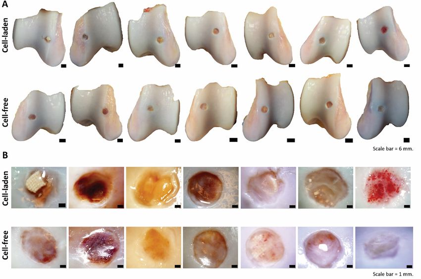
DILOKSUMPAN ET AL. EMPIRICAL 7

 (except for the case referred to above that was euthanized), for both the head
 and the pelvis, there was no clear pattern in the direction of the asymmetries
 between baseline and endpoint and those differences between baseline and
 endpoint were minimal and statistically not significant. Therefore, symmetry
 measures could not discriminate between cell-laden and cell-free constructs.
 Further, there was also no clear effect of timepoint on pelvis roll and pelvis
 yaw range of motion (Supplementary Figure 12), however, pelvis pitch range
 of motion (ROM) (Figure 6C) decreased for all subjects with almost 20% over
 time (Supplementary Table 1).

 Limb parameters, effects of time
 There was a significant effect of time for the height the toe was lifted from the
 surface during the swing phase of the limb that decreased significantly in the
 cell-free treated limbs, but not in the limbs treated with cell-laden constructs
 (Supplementary Table 1). The only other significant effect of time was a
 decrease in the extension of the metacarpophalangeal joint of the forelimb
F I G U R E 5 Representative pictures show white fragments of broken ipsilateral to the hind limb that had been treated with cell-laden constructs,
ceramic after press-fitting cell-laden and cell-free osteochondral constructs
 indicating unloading of that forelimb (Supplementary Table 1).
into the defect. Black arrows indicate the position of some visible
bioceramic fragments. White arrows indicate protrusion of the chondral
 Limb parameters, differences between cell-laden and cell-free at
compartment
 endpoint
 There were no significant differences between any of the cell-laden and cell-free
of some cell-laden constructs, the surface of the chondral compartment was limb parameters at the end of the experiment. Results from the linear mixed
not level over the entire circumference with the surrounding native cartilage model are shown in Supplementary Table 2.
after press-fitting into the defect site.
 Radiographic examination
 Post-operative clinical monitoring Healing progression within the osteal compartment of the implanted osteo-
After surgical implantation, the animals were checked clinically for physical chondral constructs was followed up non-invasively through radiographic
appearance and vital signs on a daily basis. All ponies recovered well from examination. On the radiographs taken at baseline, 3, and 6 months, no obvi-
anesthesia after surgery and passed uneventfully through the rehabilitation ous abnormalities in term of the architecture of the surrounding native tissue
period without any abnormalities in body temperature or behavior, with good were detected, other than the defects that had been created. This was with the
weight-bearing on all operated limbs and no clinical signs of lameness during exception of the pony that developed severe lameness. In that animal, severe
the entire period, with the exception of a single pony that developed severe lame- osteolysis was noted at the implantation site 3 months after the implantation
ness at 10 weeks after surgery. This pony was treated with anti-inflammatory (Supplementary Figure 13).
medication and examined radiographically, which revealed extensive osteolysis
around the created lesion. Because of persistent discomfort, the pony was Post-mortem macroscopic evaluation of the repair tissue
euthanized at 12 weeks after surgery. Therefore, it was excluded from all Macroscopic characteristics, for instance, color, appearance, and filling level
analyses. of the lesion, were observed and documented before harvesting tissue sample
 for further analyses. After 6 months, macroscopic evaluation revealed that the
 Gait analysis defects were filled with repair tissue that in all cases did not fill the entire defect
Objective gait analysis was used to check for lameness or other signs of dys- and remained lower than the level of the surrounding native cartilage in both
function of the musculoskeletal system. Objective data retrieved before implan- cell-laden and cell-free treatments (Figure 7A). The color of the repair tissue
tation and at the end of the experiment were assessed for relevant parameters, was variable (from reddish, to yellow and translucent) within the different
including symmetry parameters and limb parameters. treatments (Figure 7B). In some cases, ceramic fragments could be observed
 within the repair tissue of the chondral compartment.
Symmetry parameters
Front and hind limb lameness were analyzed through evaluation of the sym- Biochemical analyses of repair tissue within the chondral
metry parameters of the head (MinDiff Head (Figure 6A)) and of the pelvis compartment
(MinDiff Pelvis (Figure 6B)). These values reflect the differences in minimal The deposition of GAGs and collagen, the two main elements that compose
vertical displacement with a negative MinDiff indicating a left-sided asym- cartilage extracellular matrix, were quantified within the chondral compart-
metry and a positive MinDiff a right-sided asymmetry. In the treated ponies ment of the osteochondral graft 6 months after implantation. There were no

Journal of Trial and Error 2021 View interactive version here.
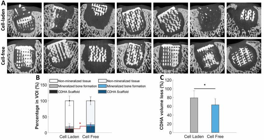
8 EMPIRICAL DILOKSUMPAN ET AL.

F I G U R E 6 Gait analysis: Symmetry parameters. Symmetry data of the head (A) and pelvis (B) show no consistent differences over time. However, pelvis
pitch decreased consistently in all individuals (C).

 F I G U R E 8 Biochemical analysis from chondral compartment at the
 defect site after an implantation for 6 months. Quantitative analysis of
 GAG·DNA-1 between cell-laden and cell-free treatments (A). Quantitative
 analysis of collagen⋅ DNA-1 between cell-laden and cell-free treatments (B)
 ( = mean). Grey dotted line indicates level in native cartilage.
F I G U R E 7 Macroscopic appearance of the repair tissue and
surrounding native tissue in all individual animals at euthanasia.
 2.19 ± 0.77 ) (Figure 9C, 9D). However, the compression modulus of the
Macroscopic appearance of the defect site and surrounding femoral ridge
(A). Close-ups of macroscopic appearance at the defect site (B). native tissue was substantially higher (approximately 5 − 6-fold) than inside
 the chondral compartment of the implant.

significant differences in either GAGs (cell-laden: 30.46 ± 15.95 ⋅ −1 , Micro-CT evaluation of repair tissue within the osteal
cell-free: 24.44 ± 15.31 ⋅ −1 ) or collagen expressed per DNA (cell-laden: compartment
79.66 ± 91.21 ⋅ −1 , cell-free: 134.21 ± 153.73 ⋅ −1 ) between the Bone healing and integration after was assessed through micro-CT scanning 6
chondral compartments of the cell-laden and cell-free constructs (Figure 8A, months after implantation. Micro-CT images showed significant bone loss sur-
8B and Supplementary Figure 14). However, all values were substantially rounding the implant in both the cell-laden and the cell-free groups, which could
lower than those from native cartilage (Figure 8, grey dotted line) that was be visualized as black areas between the porous bioceramic structure (white)
harvested distantly from the defect site. and the surrounding native bone (grey). However, mineralized bone formation
 could be visualized in some scaffolds from both groups with an integration to
 Biomechanical properties of the repair tissue within the neighboring native bone (Figure 10A). Statistically, there were no significant
chondral compartment differences in mineralized bone formation (cell-laden: 6.14% ± 10.09%, cell-
Compressive strength of the chondral compartment was assessed and compared free: 4.73%±4.93%) and non-mineralized tissue (cell-laden: 81.38%±15.37%,
in three different locations: the defect site, adjacent surrounding native tissue, cell-free: 74.71% ± 12.44%). However, there was a significant difference
and distant surrounding native tissue (Figure 9A), the latter two as control in the amount of remaining ceramics between the two groups (cell-laden:
measurements from healthy cartilage tissue. There were no significant differ- 12.48% ± 9.75%, cell-free: 20.56% ± 10.54%( = 0.0313)) (Figure 10B). In
ences in the Young’s modulus of the chondral compartment between cell-laden line with this, there was a difference in the degradation of ceramics in the
(0.31 ± 0.13 ) and cell-free (0.42 ± 0.19 ) constructs (Figure 9B). cell-laden construct versus the cell-free constructs (cell-laden: 79.02 ± 16.18%,
This was also true for two sites of the native cartilage, one close to the border of cell-free: 63.20 ± 13.90%( = 0.0313)) (Figure 10C).
the defect (cell-laden: 1.75 ± 0.80 , cell-free: 2.22 ± 0.48 ) and one
at 5 − 10 from the defect boundary (cell-laden: 1.86 ± 0.78 , cell-free:

View interactive version here. Journal of Trial and Error 2021
DILOKSUMPAN ET AL. EMPIRICAL 9

 Discussion
 This study aimed to evaluate the efficacy of an engineered osteochondral com-
 posite scaffold that was fabricated by combining a proven osteogenic CDHA
 scaffold for the osteal compartment with a novel interface for the connection
 between the chondral and osteal compartments. For the chondral compartment,
 BMP-9 stimulated cell-laden and cell-free constructs were compared. The
 cell-laden constructs contained in vitro formed tissue that was rich in GAGs
 and type II collagen, obtained by seeding Articular Cartilage Progenitor Cells
 (ACPCs) and stimulating them with BMP-9 for 4 weeks prior to implantation.
 After implantation in an equine osteochondral defect for 6 months, there was
 poor chondral repair tissue in both the cell-laden and cell-free implants. The
 repair tissue was akin to fibrocartilage and was characterized by the presence of
 fibrous tissue with low content of GAGs and type II collagen and a degenerated
 surface. The CDHA scaffold had failed to act as an osteal anchor, as evidenced
 by the radiographical images showing misalignment and partial collapse of the
 CDHA construct, the presence of CDHA fragments within the defect and in
 the surrounding tissues, and a limited volume of newly formed calcified bone
F I G U R E 9 Compression modulus of the chondral compartment at the
defect site and surrounding native cartilage of harvested samples 6 months in the pores of the osteal anchor.
after implantation. Schematic picture demonstrating locations where In the quest for a method to achieve satisfactory and durable repair of ar-
mechanical properties were analyzed (A). Compression modulus of the ticular cartilage, several osteochondral grafts that incorporate cells and that
chondral compartment of cell-laden and cell-free constructs at 6 months were manipulated to optimize biochemical and biomechanical properties, have
(B) and at two sites of the native cartilage, close to the border of the defect
 been investigated in the past decades (Huang et al., 2016). Articular Cartilage
(C) and further away (D). ( = mean).
 Progenitor Cells have become a promising cell source due to their ability to re-
 tain their chondrogenicity after their expansion for several passages (Williams
 Histological evaluation of the osteochondral repair tissue et al., 2010). Recently, growth factor BMP-9 was shown to be a potent stimu-
Histological slides were assessed to identify the composition of the repair lator of chondrogenic differentiation of this cell type in vitro (Morgan et al.,
tissue matrix deposited within the defect site. In the chondral compartment, the 2020). This warranted further investigations to evaluate the use of BMP-9
defect sites of both cell-laden and cell-free structures were filled with fibrous stimulated ACPCs for cartilage repair in vivo. Indeed, the cell-laden chondral
repair tissue with degenerated and necrotic superficial surface with minimal compartment showed a high presence of neo-cartilage extracellular matrix
inflammatory reaction, as revealed by H&E and safranin-O staining (Figure production after pre-culture at the time of implantation, yet the average GAG
11, Supplementary Figure 15, Supplementary Figure 17, and Supplementary content decreased approximately 6.5-fold during the in vivo implantation pe-
Figure 18). Integration at the boundary of the defect between chondral repair riod. The GAG content of cell-laden constructs in fact decreased to the level of
tissue and surrounding native cartilage was observed in both groups. The the cell-free constructs, suggesting loss or disintegration of the in vitro formed
production of GAGs, type II collagen, and type I collagen was very limited in the tissue. Which factor initiated this loss of in vitro formed tissue remains unclear.
repair tissue in both groups (Figure 11). The organization of the collagen fibrils A previous study from McCarthy et al. (2012) demonstrated superior results
in both groups seemed random, without any hierarchical pattern that could be in using ACPCs for cartilage repair in an equine model, in comparison with
identified by polarized light imaging of picrosirius red staining. Additionally, mesenchymal stem cells. However, due to the use of different materials and
the special distribution of PCL-microfibers, which had disappeared because of cell culture protocols, it is impossible to directly compare those results with
the xylene treatment during sample preparation, was still traceable within the the ones from the current study. Several factors might have been involved in
chondral compartment of both groups (1 out of 7 for cell-laden and 5 out of 7 the deterioration of the chondral compartment in this study, most prominently
for cell-free structure). mechanical stresses due to the partial failure of the osteal basis and the resulting
 In the bone compartment, there was positive staining for type I collagen poor osteointegration (Heuijerjans et al., 2018).
in some scaffolds from both groups at places where there were islands of The nature of the osteal anchor is an important factor when developing
new mineralized bone formation. There were multifocal coalescing spots of tissue-engineered osteochondral implants. Much work has been done on the
inflammatory reaction characterized by macrophages, multinucleated giant development of several types of bone grafts and many of these are routinely
cells, lymphocytes, eosinophils, and plasma cells (Supplementary Figure 16, used in clinical settings (Oryan et al., 2014), so of the various elements of
Supplementary Figure 17, Supplementary Figure 18). an osteochondral implant, the bone part is seemingly the least difficult one.
 However, the relationship between the osteal anchor and the quantity and
 quality of the repair tissue in the chondral compartment has been the subject of
 debate (Bal et al., 2010) and it is still unclear what osteal anchor would form the

Journal of Trial and Error 2021 View interactive version here.
10 EMPIRICAL DILOKSUMPAN ET AL.

F I G U R E 1 0 Representative micro-CT images from the middle of the sagittal plane of the constructs and quantification from 3D-reconstruction of micro-CT.
Representative micro-CT images from the middle of the sagittal plane of the constructs (white = ceramics, grey = mineralized tissue, black =
non-mineralized tissue) (A). Quantitative analysis from micro-CT reconstruction showing percentage of mineralized bone formation, non-mineralized
tissue, and remaining ceramics (B). The volume loss of ceramics was slightly higher in the cell-laden constructs compared to the cell-free ones (C).

best base for facilitating cartilage repair. The exact same bioceramic material identical (7 months in the earlier study, 6 months in the current), which makes
tested in this long-term, orthotopic equine study, had previously been shown direct comparisons between the two impossible. However, there were clear
to successfully guide osteoregeneration in the same species, when implanted histological differences with many more multifocal to coalescing inflammatory
in the tuber coxae, an anatomical locus less subject to intense mechanical reactions in both cell-laden and cell-free implants in the current study, compared
loads (Diloksumpan, de Ruijter, et al., 2020). Additionally, this previous to the earlier study, in which there were very few inflammatory cells visible.
study also focused on comparing different pore architecture within the 3D This difference is likely due to the chronic irritation caused by fragments of
printed bone scaffolds. The scaffold architecture that led to the highest rate material and to instability resulting from the imperfect fit of scaffold within
of new bone formation, consisting of a constant pore size across the sample, the defect in the current study.
was selected for the present study, with the goal of maximizing neo-bone Some scaffolds from the current study collapsed and showed misalignment
repair (Diloksumpan, de Ruijter, et al., 2020). However, there are two major of the CDHA structure within the defect, with slightly enlarged defect size
differences with the use of the material in the current study. First, in the previous after an implantation for 6 months (as evident from the micro-CT analysis).
study the material was implanted in the tuber coxae, which is an orthotopic Bone resorption around the implant was found both in the groups with cell-
area but not representative of the intra-articular environment. Second, in the laden and with cell-free chondral compartment, which infer the effect from the
former study the implant was surrounded by a cylindrical case made of PCL osteal anchor rather than from the variable within chondral compartment. The
that served to prevent bone ingrowth from the sides. Without such a shell of the circumstances described above likely resulted in failure to place the implant in
mechanically deformable PCL in the current study, the surgeon encountered a real press-fit fashion and hence, in the creation of (micro)movement, leading
difficulties during the surgical placement of the implants, provoked by the to increasing instability under repetitive loading together with possible material
non-resilience and brittleness of the CaP-based material, combined with some degradation over time and ensuing osteolysis, as seen earlier (Albrektsson et al.,
deviation from an ideal cylindrical shape of the CDHA implant. This resulted 2019; Goodman et al., 2019). Additionally, the gap between the implant and
in fragments breaking off from the bioceramic osteal anchor. In fact, although surrounding native tissue due to the imperfect fit may have allowed for the
inadvertently and as a side-effect, this problem of fragment formation was intrusion of synovial fluid. Contact of synovial fluid with subchondral bone
avoided in the former study when using PCL to encase. Polycaprolactone has been shown to induce osteolysis (Kold et al., 1986). In the few scaffolds
is deformable material, and the encasing will have facilitated the sliding of that remained in place, the volume of mineralized bone formation was also
the ceramic implant into the defect. The duration of both studies was not lower than what was found in the earlier study, both in cell-laden and cell-free

View interactive version here. Journal of Trial and Error 2021
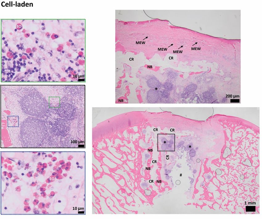
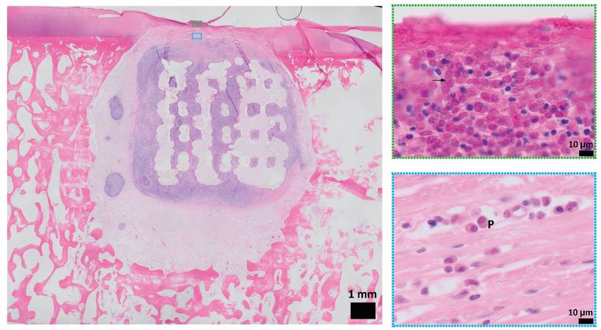
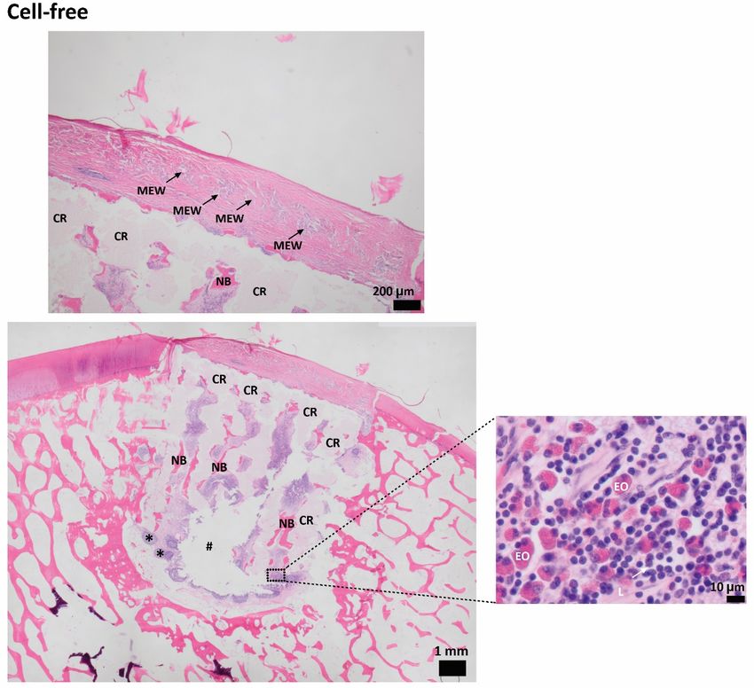
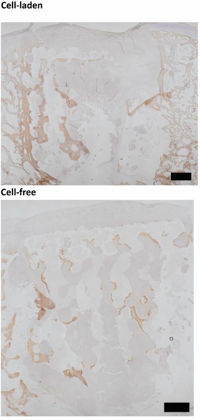
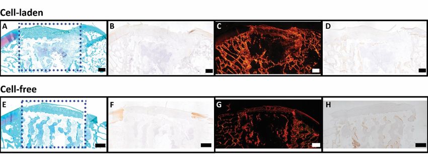
DILOKSUMPAN ET AL. EMPIRICAL 11

treatments. This is potentially due to the higher and cyclical loads experienced delocalized MEW-mesh structures were observed in some scaffolds from both
in the articulating joint compared to the tuber coxae. Overall, it was not possible groups. This might be due to misalignments of the osteal compartment as
to determine a single cause for the failure of the CDHA scaffolds to act as discussed above, to shear forces during loading, or a combination of both.
the anchor of the engineered osteochondral implant, and it is likely that the During the in vivo post-operative monitoring of the animals, the clinical
limited osteointegration is due to a combination of misalignment after surgery, signs were very mild and far from alarming, except for the single pony that
mechanical failure under cyclic loading, and synovial fluid infiltration. developed severe lameness. Clinical examinations were performed routinely by
 In earlier studies (Bothe et al., 2019; van Susante et al., 1998) similar experienced veterinary specialists, however, assessment of locomotion through
observations were made. In those studies, fibrous repair tissue was seen in visual observation alone is subjective and known to have poor repeatability,
the chondral compartment, together with osteolysis and formation of a fibrous especially in mild cases. This is partly due to the inability of human visual per-
interface surrounding the osteal anchor when tissue-engineered osteochondral ception to properly distinguish, notice, and quantify differences in locomotion
grafts were implanted in a load-bearing area for a 12-month long-term study. at high resolution (Serra Bragança et al., 2018). Therefore, quantitative gait
It was hypothesized that osteolysis and the fibrous layer surrounding the osteal analysis was employed as an objective and non-invasive assessment. The gait
anchor led to instability that might have caused the degradation of the newly analysis data did not show many differences with respect to baseline. This may
formed cartilage-like repair tissue observed at the early of the experiment. to a certain extent have been related to methodological factors. During the
Stability of the osteochondral graft might be affected by multiple parameters assessment, ponies were put on a treadmill and they were imposed the same
including the alignment of an osteal compartment within the defect and the belt velocity during both measurements. Therefore, the subjects were forced to
properties of the materials being used (Heuijerjans et al., 2018; Nosewicz et al., trot at the same velocity, ensuring that stride length needed to be maintained.
2014; Schlichting et al., 2008; von Rechenberg et al., 2003), as these might This might be the reason why there were no differences between timepoints
affect stability of the overlying chondral compartment. In the current study, for maximal protraction and retraction (the limb parameters). However, pelvis
misalignment and partial collapse of the osteal part of the construct might also pitch range of motion (ROM) decreased for all subjects with almost 20% over
be at the basis of the protrusion of the chondral compartment of some cell-laden time. This pattern is often seen in case of dysfunction of the back. The finding
constructs and the inconsistent position of the chondral graft with respect to may thus be related to earlier observations that bilateral hindlimb lameness
the surrounding native tissue in both groups. These conditions may have led may induce back problems in horses (Alvarez et al., 2008; Alvarez et al., 2007;
to an abnormal load distribution, possibly inducing inferior biomechanical Greve et al., 2017). Toe dragging of the lame limb, in which the hoof is lifted
properties (Bowland et al., 2015). It is thus clear that the imperfect implantation less high off the ground, is another sign of pain (Buchner et al., 1995). Never-
had severe repercussions and can be considered a major factor that affected theless, the overall impact of the bilateral lesions in the stifle joints was low,
the chondral compartment and hence the outcome of the study. This effect as evidenced by the fact that there was no sign of load redistribution from the
was noticeable to the extent that drawing any conclusions about the effect of hind to the front limbs. If that had been the case, the subjects would have
BMP-9 seeded ACPCs, which was the principal variable that was to be tested compensated by displacing their center of mass more to the front, resulting in
in the study, is not possible. Also, no conclusion could be reached about the more negative angles for forelimb fetlock extension, as fetlock hyper extension
interface between the osteal and chondral compartments that was used since correlates with peak ground reaction force (GRFPeak) (Crevier-Denoix et al.,

F I G U R E 1 1 Representative histological images from the center part of cell-laden and cell-free structures after implantation for 6 months. Safranin-O/fast
green (red color = positive) (A, E); Collagen type II (brown color = positive) (B, F); Picrosirius-red (C, G); collagen type I (brown color = positive) (D, H) of
cell-laden (A-D) and cell-free structures (Scale bar = 1 ).

Journal of Trial and Error 2021 View interactive version here.
12 EMPIRICAL DILOKSUMPAN ET AL.

2010), where less negative angles indicate a lowered GRFpeak. In fact, only Alvarez, C. B., Bobbert, M. F., Lamers, L., Johnston, C., Back, W., & van
the fetlock angles of the forelimb ipsilateral to cell-laden construct changed, Weeren, P. R. (2008). The effect of induced hindlimb lameness on tho-
becoming less negative, hence indicating unloading rather than additional racolumbar kinematics during treadmill locomotion. Equine Veterinary
loading (lower GRFpeak). The reason for this is not clear. Journal, 40(2), 147–152. https://doi.org/10/bsjkv7
 It can be concluded that even seemingly minor modifications of a successful Alvarez, C. B., Wennerstrand, J., Bobbert, M. F., Lamers, L., Johnston, C., Back,
implant may have grave consequences and extrapolation is dangerous in the W., & Weeren, P. R. (2007). The effect of induced forelimb lameness on
complex in vivo situation. In this case, the failure of the osteal compartment of thoracolumbar kinematics during treadmill locomotion. Equine Veterinary
the construct, the use of which seemed well-backed by solid in vivo data, did not Journal, 39(3), 197–201. https://doi.org/10/djxztr
permit drawing conclusions about the original hypotheses. Given the relatively Bal, B. S., Rahaman, M. N., Jayabalan, P., Kuroki, K., Cockrell, M. K., Yao,
frequently occurring, rather disappointing results of in vivo orthotopic testing J. Q., & Cook, J. L. (2010). In vivo outcomes of tissue-engineered osteo-
of promising techniques for joint repair, it may be wise to put more emphasis chondral grafts. Journal of Biomedical Materials Research Part B: Applied
on performing pilot experiments before embarking on a full-scale in vivo study Biomaterials, 93(1), 164–174. https://doi.org/10/cn94hf
in a large animal experiment (R. A. Vindas Bolaños et al., 2017). Functional Bothe, F., Deubel, A. K., Hesse, E., Lotz, B., Groll, J., Werner, C., Richter, W.,
joint repair remains a huge challenge that has not been addressed to some & Hagmann, S. (2019). Treatment of focal cartilage defects in minipigs with
satisfying extent during the last decades, despite many promising approaches. zonal chondrocyte/mesenchymal progenitor cell constructs. International
It is likely that the quest for a real solution will go on for some time by trial Journal of Molecular Sciences. https://doi.org/10/gh63z7
and error with more errors to come. Those errors are inevitable and need to be Boushell, M. K., Hung, C. T., Hunziker, E. B., Strauss, E. J., & Lu, H. H.
made but they should take the least possible toll on experimental animals. (2017). Current strategies for integrative cartilage repair. Connect Tissue
 Research, 58(5), 393–406. https://doi.org/10/gf5bw7
Conclusion Bowland, P., Ingham, E., Jennings, L., & Fisher, J. (2015). Review of the
This study presented the results from the evaluation of a cell-laden and cell- biomechanics and biotribology of osteochondral grafts used for surgical
free versions of an osteochondral implant for cartilage repair in a challenging interventions in the knee. Proceedings of the Institution of Mechanical
in vivo large animal model. The osteal anchor of this osteochondral implant, Engineers, Part H: Journal of Engineering in Medicine, 229(12), 879–888.
composed of a bioceramic material that had previously been proven to facilitate https://doi.org/10/gh63z6
mineralized new bone formation in the same species, failed to perform as Buchner, H. H., Savelberg, H. H. M., Schamhardt, H. C., & Barneveld, A.
an effective fixation with sufficient stabilization for both cell-laden and cell- (1995). Bilateral lameness in horses a kinematic study. Veterinary Quarterly,
free osteochondral implants. This insufficient fixation was evidenced by the 17(3), 103–105. https://doi.org/10/chdqdt
extensive osteolysis, the collapse and misalignment of the osteal anchor, and the Crevier-Denoix, N., Robin, D., Pourcelot, P., Falala, S., Holden, L., Estoup,
limited volume of newly formed bone. The failure of the bone anchor hindered P., Desquilbet, L., Denoix, J. M., & Chateau, H. (2010). Ground reaction
the evaluation of the two versions of the chondral compartment for cartilage force and kinematic analysis of limb loading on two different beach sand
repair. The study shows that, even after an equivalent ceramic bone component tracks in harness trotters. Equine Veterinary Journal, 42(38), 544–551.
had shown very satisfactory results in the same species, minor differences in https://doi.org/10/dn9j57
the implant and a change in testing condition proved to be enough to lead to de Ruijter, M., Ribeiro, A., Dokter, I., Castilho, M., & Malda, J. (2019). Simul-
completely different results, in this case precluding drawing conclusions about taneous micropatterning of fibrous meshes and bioinks for the fabrication
the effect of the principal variable. This outcome stresses the need of carrying of living tissue constructs. Advanced Healthcare Materials, 8(7), Article
out in vivo pilot studies under exactly the same conditions before moving into 1800418. https://doi.org/10/gh63z5
a larger in vivo study. Diekman, B. O., & Guilak, F. (2013). Stem cell-based therapies for osteoarthri-
 tis: Challenges and opportunities. Current Opinion in Rheumatology, 25(1),
References 119–126. https://doi.org/10/f5k74n
Abinzano, F., de Ruijter, M., Mensinga, A., Castilho, M., Khan, I., Levato, R., Diloksumpan, P., de Ruijter, M., Castilho, M., Gbureck, U., Vermonden, T.,
 & Malda, J. (2018). Combining melt electrowriting of microfiber meshes van Weeren, P. R., Malda, J., & Levato, R. (2020). Combining multi-scale
 with aggregated chondroprogenitor cells stimulated with BMP-9 to enhance 3D printing technologies to engineer reinforced hydrogel-ceramic interfaces.
 cartilage tissue engineering [Conference presentation abstract]. Annual Biofabrication, 12(2), Article 25014. https://doi.org/10/gh63z4
 Meeting of the European Society for Biomaterials, Maastricht, the Nether- Diloksumpan, P., Vindas Bolaños, R., Cokelaere, S., Pouran, B., de Grauw, J.,
 lands. https://pure.ulster.ac.uk/ws/portalfiles/portal/71294610/ESB_2018_ van Rijen, M., van Weeren, R., Levato, R., & Malda, J. (2020). Orthotopic
 Abstract_Proceedings_4.pdf bone regeneration within 3D printed bioceramic scaffolds with region-
Albrektsson, T., Becker, W., Coli, P., Jemt, T., Molne, J., & Sennerby, L. (2019). dependent porosity gradients in an equine model. Advanced Healthcare
 Bone loss around oral and orthopedic implants: An immunologically based Mater, 9(10), Article 1901807. https://doi.org/10/gh63z3
 condition. Clinical Implant Dentistry and Related Research, 21(4), 786–795. Doube, M., Klosowski, M. M., Arganda-Carreras, I., Cordelieres, F. P.,
 https://doi.org/10/gg53t3 Dougherty, R. P., Jackson, J. S., Schmid, B., Hutchinson, J. R., & She-

View interactive version here. Journal of Trial and Error 2021
You can also read