The "Donut" A New Compound Support for the 9X20 Lathe
←
→
Page content transcription
If your browser does not render page correctly, please read the page content below
The “Donut”
A New Compound Support for the 9X20 Lathe
By John Pitkin
Greenville, Texas
The objectives of this project were to identify the design flaws in the compound slide
mounting and fabricate a true corrective modification.
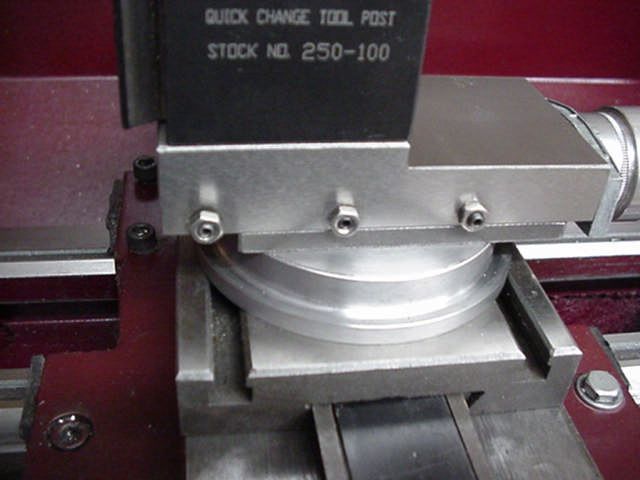
What is pictured, here, is not a clamp over the original ring base. This is a whole new
support for the compound. The compound sits on the outer ring of circular support
resembling a squashed bagel or “donut.” It is far easier to machine than any four bolt
clamp that uses the factory mount. The new donut is a solid support system for the
compound that reduces machining chatter to absolute minimum.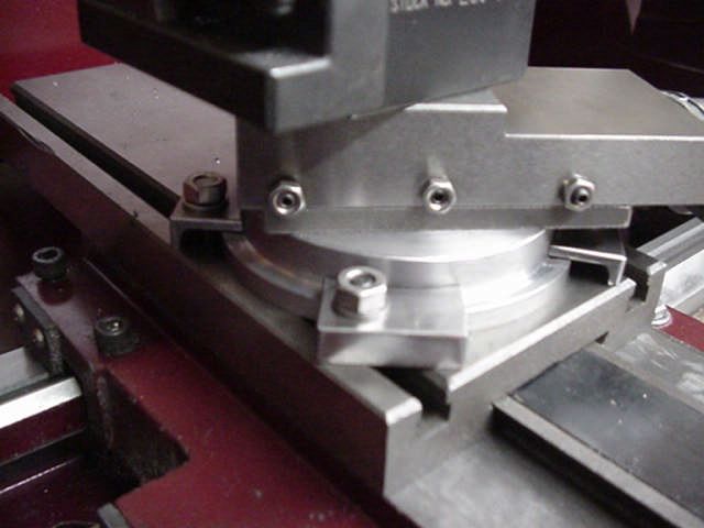
History
The factory mounting of the compound slide is a graduated ring attached to the swivel
base using three M6-1.0 x 12 FH screws. The graduated ring is held to the cross slide
with a two bolt clamp. The two bolt clamp flexes and does not support the narrow swivel
base. This led to the development of the widely used four bolt clamp.

The four bolt clamp greatly improved the rigidity of the compound. The four bolts and a
stiffer clamp held the graduated ring much tighter. Most owners also replace the three or
four FH screws with hardened button head screws.

The four bolt clamp has served users for many years and is largely responsible for the
increased functionality of the lathe. However, after doing the “four bolt clamp”, I was not
satisfied the problem was solved. The four bolt clamp improved the chatter problem, but
considering the solidity of the cross slide, I detected more flex in the compound than
should be present.

The Theory
The original graduated ring is barely two inches (50mm) in diameter. When cutting
forces are applied to the tool post, the compound slide tips on the small diameter base and
creates chatter in the workpiece. Both the stock clamp and the four bolt clamp attempt to
restrict the see-sawing motion by using a clamp in tension. I felt this is the wrong
approach.

No matter how many bolts are used, or how tightly the clamp fits under the base of the
compound, the support is simply too small in diameter.
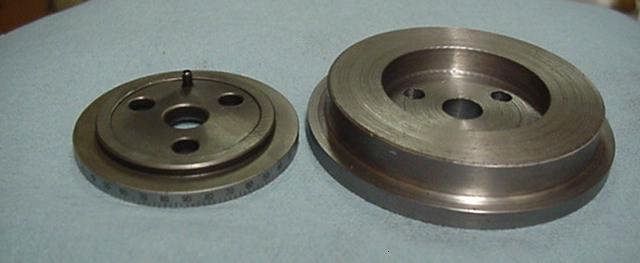
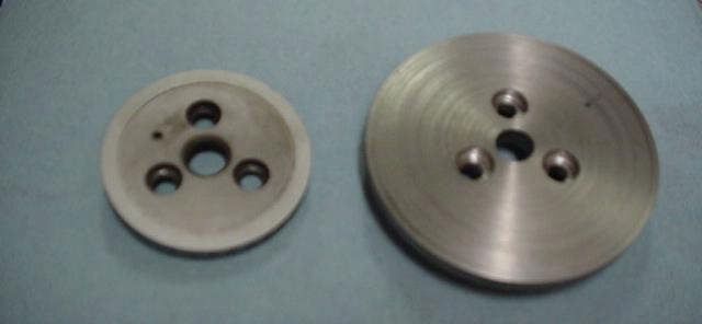
The Solution
I fabricated a new “donut” ring 3.50 inches (89mm) in diameter. The compound now sits
on the outer surface of the donut instead of standing on the center pivot. The support area
increased from approximately 3 square inches (20 cm²) to over 9.6 square inches (62
cm²). Here the stock graduated ring, left, and the donut, right, are shown for comparison.
The compound slide swivel base will fit in the center recess. .

Below are pictured the old graduated ring and the new donut showing the counter-bored
mounting holes.
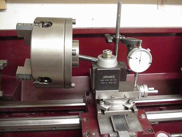
The stability of the new mount is instantly noticeable. Here the new donut is attached to
the compound and sitting on the cross slide without any hold down bolts.

Testing and Measurement
With the unit completed, I wanted to prove there was measurable improvement. To
measure the amount of deflection, I locked down the carriage, cross slide and compound
by firmly tightening the carriage lock and all the gib screws. The dial indicator base was
attached to the cross slide so the only relative movement I would be measuring was
compound deflection. I first mounted the stock graduated ring to the compound base
using a four bolt clamp. I then hung a heavy four jaw chuck on the tool post handle and
measured the deflection. It was measured between 0.0015 to 0.0018 inches. (0.0375 to
0.0455mm) Next I mounted the donut and clamping system. The deflection was
measured at less than 0.0003 inches (0.0075mm).*

Based on these results, this new donut mounting system is five times stiffer than the stock
mount, even if using a four bolt clamp.

[*Note: Measurements were taken by adding and removing the weight several times, and
checking the indicator returned to reference zero after each reading. Readings not
returning to zero were deemed invalid.]
Below: Testing deflection with the new “donut” base.

The new mounting system attributes its stiffness due to the major components being in
compression and a much wider supporting area.

Some other advantages of the donut mount:

Removal of the compound is much easier. Loosen the four nuts and they slide out of the
t-slots. No need to take the nuts and washers all the way off the T bolts.

The new donut may be scribed with degree markings and used for accurate angle setting
of the compound. Nothing covers or hides the edge of the base. (As of this writing, the
author had not marked the pictured donut. A locating pin will be added to index the
graduations after the donut is marked. A pin is not necessary for rigidity.)
Fabricating the “Donut”
Machining the donut is very easy. None of the dimensions is critical. Approximate
measurements are given in inches and (metric)

The thickness of the donut is 0.625 (16mm). This approximates the original height of the
compound slide. Tool post height is unchanged. It is not recommended to make the donut
thicker than 0.625” (5/8”) or 16mm. Keeping the donut low profile will ensure no milling
of the compound is necessary if the owner installs a quick change tool post.

The major OD, to the outside of the flange is 3.50 inches (89mm)

The minor OD is 3.00 inches (76mm) to allow a 0.250 wide flange (6.35mm) for
clamping. The outer flange is 0.250 tall and deep. (6.35mm)

The small center bore is 0.476 (12mm). The small hole allows the compound pivot to
protrude though the base and plug into the cross slide pivot hole.

Your existing compound swivel base fits into the large center recess or the “donut hole”.
The hole is approximately 1.90 ID (48.26mm) by 0.315 (8mm) deep. These actual
dimensions depend on your compound base.

Important: The round base of the compound bottom swivel should just clear the bottom
of the recess to ensure good perimeter contact. Repeat… the swivel base does NOT touch
the surface in the bottom of the donut hole recess. When assembled, there should be
solid contact between the outer surface of the donut and the compound slide bottom face.

Caution: the three factory screw holes on my factory graduated ring and swivel base are
NOT symmetrically spaced. Do not assume yours are symmetrical.

To accurately locate the mounting screw holes, use the old graduated ring as a template.
Remove the old graduated ring and drive the locating pin out of the old ring in order for
the ring to lay flat when marking the holes. Next, place both rings on the swivel base to
align the center holes. The top of the old ring should be facing the bottom of the new
donut. Then, using a transfer punch, mark the hole locations. Be sure you do not invert
the original ring base when marking the new mounting hole locations.

The mounting holes are drilled and counter-bored for hardened M6-1.0 x 12 button head
screws. This is easiest to accomplish on a mill but can be done using a drill press.
Step by Step Machining Instructions

1. Rough cut the oversize ring.

Get a piece of plate material about 4 x 4 x ¾ inch. Cut off the corners with hack saw or a
band saw to reduce the amount of machining to make a round plate.

2. Mount it on the lathe.

Drill a 7/16 or 11 mm hole through the center.

Chuck a 7/16 x 3 inch bolt in the lathe with the head inside the chuck so it hooks onto the
inside of the chuck jaws. Close the Jaws on the bolt. The threads of the bolt will be
protruding.

Slip the workpiece over the bolt and up against the chuck jaws. Tighten with a nut firmly
using a wrench.

3. Make the blank round

Begin by making an interrupted cut on the outside diameter to make the blank round. Go
slowly as you cut off the corners. Do not try to take too deep a cut. A few thousands at a
time is safe. The lathe will bang and thump throwing off small chips until the piece is
round, then the cutting will smooth out and produce long curly chips.

4. Turn outside diameter to 3.5 inches and cut a clamping ledge.

Cut a clamping ledge on the outer edge. The ledge is 0.25 high and 0.25 deep. This
means your major OD is 3.5 inches and your minor OD is 3.0 inches. Leave a bit of extra
height to the ledge, as you will face the bottom in the next step.

5. Face the bottom

Remove the workpiece from the lathe.
Remove the bolt from the chuck.
Mount the workpiece in the lathe using outside jaws clamped in the ledge. The bottom of
the workpiece is to the right.
Take a shallow face cut across the workpiece to flatten the bottom. Face cut enough to
make the ledge 0.25 thick.

6. Face the top

Turn the workpiece over in the chuck. The top is to the right. Face the top to reduce the
total thickness of the piece to 5/8 inch. (0.625)
7. Cut the center recess.

Machine a recess in the top center 1.90 wide x 0.315 deep.
Bore the center hole to 12mm
Remove the workpiece from the lathe.

8. Drill mounting holes

Remove the original graduated ring from the bottom of the compound and discard the
original Allen head screws. These screws are much too soft to hold the base. Remove the
original two bolt, or four bolt replacement clamp ring. It is not used.

Locate mounting holes to match your existing holes in the compound base.
The holes are NOT symmetrically spaced on my lathe. Yours may be different.
Drill counter-bores first. The counter-bores should be deep enough for M6-1.0x12 button
head Allen screws. About 0.20 deep. Then drill through holes for the button head screws.

Tip: You can use the original graduated ring to locate the holes on the new ring base. You
must remove the locating pin from the old ring in order to hold the parts together. Do not
place the pieces bottom to bottom as the orientation will NOT be correct. They must be
held bottom to top.

9. Install new oversize ring.

The original compound base rests on the outer ring of the new donut. The pivot sits inside
the donut hole. The center 12mm stub of the compound protrudes through the bottom of
the donut to act as a swivel on the cross slide. Attach the new oversize ring with new
button head Allen screws. Use a bit of Loc-tite to retain the screws.

10. Make four small angle clamps from angle iron or aluminum.

Refer to the article to see the shape and size. The leg on the clamp is 0.25 high to match
the height of the ledge on the new ring base.

11. Attach the compound assembly to the cross slide.

Use two or four hold down clamps and bolts.

.
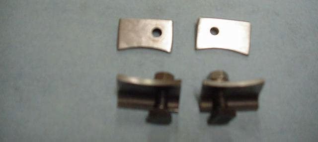
The Hold Downs
To hold the new support in place on the cross slide, I made hold-downs similar to ones
used on end mill tables.

The hold downs are constructed from 3/4 X 1/8 inch angle iron. They are easily made
using a hack saw, files and drill

The four hold downs are shown. The two on the top are right side up. The lower two are
shown with bolts and t-nuts installed. The arc on the hold downs fit the clamping ledge
on the donut. The bolt holes are off-set to allow the hold downs to span the t-slots. They
are made with left and right bolt hole off-sets.

.
Notes:

Hold downs were used instead of a large ring type clamp. A clamp ring will not improve
rigidity and adds to the complexity.

Information here may be distributed freely without compensation.
Many thanks to members of the Yahoo 9X20lathe group for inspiration on this project.

This mount is easy to make and results in a much stiffer lathe. I am confident you will
find the “donut” to be an improvement over any four bolt clamp using the stock
graduated ring.

John Pitkin
Cedar Creek Run
Greenville, TX
Addendum February 13, 2006

A few people noted a similarity of this mount to others posted on the 9X20lathe Yahoo!
group. To clarify, this mount is simply an oversize version of the original factory
graduated ring. Given the size limitations of the cross slide and the available space
between the cross slide and the swivel base, it is not surprising the dimensions and shape
are nearly identical to other mounts. It is a physical limitation, not an artistic design
interpretation. Perhaps the others also are variations of the original factory ring.

The dimensions of the donut, specifically the OD, allow the compound to travel its full
range, without bumping the leadscrew wheel into the ring or the hold downs; and, to
prevent the hold downs from overhanging the sides of the cross slide.

The primary difference of this mount is the attachment. The donut uses the factory screw
holes and does not require drilling or tapping of any original parts. I didn't think many
new lathe owners would try it if they had to drill holes in their compound. The user, may,
if desired, return the lathe to factory configuration.

As for similarity to other mounts, there is not much room for variance.

The design criteria were as follows:

It must be made on a lathe with beginner level skill, no end mill required for machining.
It’s as wide as possible for maximum support.
It does not increase tool holder height to allow installation of a quick change tool post.
It must have a ledge for clamping to the cross slide while allowing it to swivel.
The mounting screws must utilize the existing tapped holes.
It must use simple shop made hold downs.

That pretty much says what the mount will look like. However, some credit is due to the
following for aiding in the design:

It is the size of a thrust washer from a Caterpillar D5; my thanks, to Cat™.
It uses screws for the attachment; my thanks, to Archimedes.
It has a hole in the middle; my thanks, to Dunkin Donuts™.

JP

Version 1.3 April 08, 2008 Renamed the “Donut” for identification. Consolidated
machining instructions with main file.
Version 1.2 Apr 12, 2006 Clarified machining instructions
Version 1.1 Feb 13, 2006 Corrected grammatical errors, added note.
Version 1.0 Jan 25, 2006
You can also read