Tough Nature-Inspired Helicoidal Composites with Printing-Induced Voids
←
→
Page content transcription
If your browser does not render page correctly, please read the page content below
ll
                                                                                                                   OPEN ACCESS

Article
Tough Nature-Inspired Helicoidal Composites
with Printing-Induced Voids
                                                                                      Sha Yin, Haoyu Chen, Ruiheng
                                                                                      Yang, ..., Yiu-Wing Mai, Jun Xu,
                                                                                      Robert O. Ritchie

                                                                                      shayin@buaa.edu.cn (S.Y.)
                                                                                      jun.xu@uncc.edu (J.X.)
                                                                                      ritchie@berkeley.edu (R.O.R.)

                                                                                      HIGHLIGHTS
                                                                                      Micron-scale voids are observed
                                                                                      adjacent to the Bouligand
                                                                                      structures in mantis shrimp

                                                                                      Bioinspired composites are
                                                                                      printed to mimic Bouligand
                                                                                      architectures with voids

                                                                                      The impact energy of the printed
                                                                                      composites is enhanced by the
                                                                                      presence of the voids

                                                                                      FEA modeling shows that voids
                                                                                      expand and guide twisting cracks
                                                                                      to enhance toughness

Micro-scale voids are discovered in the exoskeletons of Odontodactylus japonica.
Yin et al. print bioinspired composites to mimic this material, which are found to
have superior specific impact energy in the presence of voids. Simulations indicate
that the voids expand and coalesce on loading, contributing to impact toughness.

                                                                                      Yin et al., Cell Reports Physical Science 1,
                                                                                      100109
                                                                                      July 22, 2020 ª 2020 The Author(s).
                                                                                      https://doi.org/10.1016/j.xcrp.2020.100109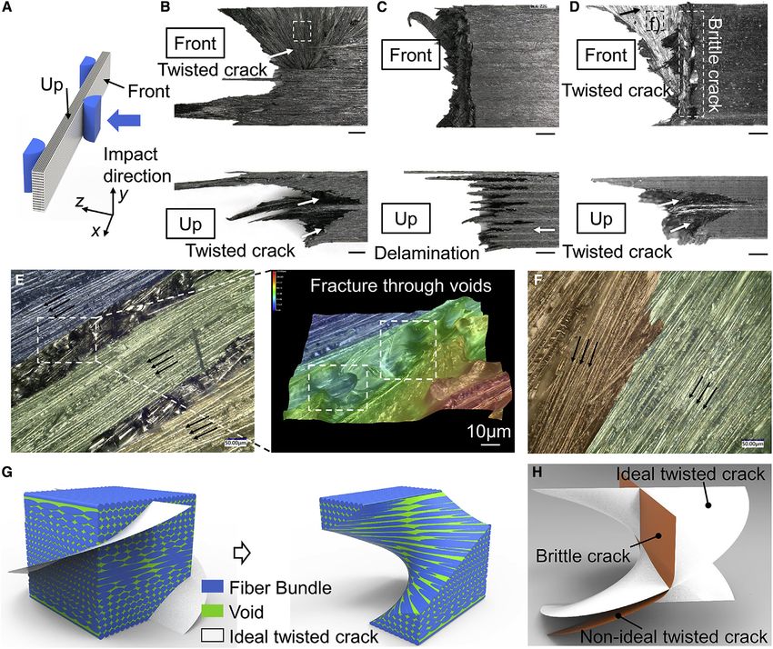
ll
                                                                                                                               OPEN ACCESS

Article
Tough Nature-Inspired Helicoidal Composites
with Printing-Induced Voids
Sha Yin,1,* Haoyu Chen,1 Ruiheng Yang,1 Qinghao He,2 Dianhao Chen,1 Lin Ye,2 Yiu-Wing Mai,2
Jun Xu,3,* and Robert O. Ritchie4,5,*

SUMMARY
Exoskeletons of Odontodactylus japonicas, the ‘‘smasher-type’’
mantis shrimp, feature a raptorial appendage comprising a Bouli-
gand architecture of chitin nanofibrils with newly observed voids
or defects between the polysaccharide a-chitin and protein inter-
faces. Here, we use a continuous-fiber 3D printing technology to
simulate such materials in carbon fiber-reinforced (helicoidal) com-
posites, complete with the presence of voids due to imperfect print-
ing. The specific impact energies of the 3D printed helicoidal com-
posites are clearly superior and further enhanced by the presence
of the voids. To explain the role of the Bouligand architecture, inter-
laminar stresses are computed and found to yield anti-delamination
characteristics, and a theoretical model is derived to evaluate the
optimal helicoidal architecture. Finite element modeling indicates
that the voids tend to deform and coalesce on loading and appear
to guide the fracture into the formation of an ideally twisted crack
in the printed helicoidal composites, thereby contributing to the
impact toughness.

INTRODUCTION
Biological materials invariably feature complex hierarchical microstructures that can
exhibit excellent mechanical properties. As an example, during millions of years of
evolution, some crustaceans have developed extremely strong, stiff, and tough exo-
skeletons to resist attack1 and weapons to engage in attack.2 The stomatopod dactyl                1Vehicle Energy & Safety Laboratory (VESL),
club of the ‘‘smasher-type’’ mantis shrimp, for instance, can impose intensive impact              Department of Automotive Engineering, School
loads of >10 kg at a speed of 23 m/s without generating structural failure.3 To                    of Transportation Science & Engineering,
                                                                                                   Beihang University, Beijing 100191, China
accomplish this feat, the structure of the appendage comprises three primary re-                   2Centre for Advanced Materials Technology,
gions, each with a distinct architecture—the impact, periodic, and striated re-                    School of Aerospace, Mechanical, and
gions.4–6 Of interest to the present study, the periodic region normally consists of               Mechatronic Engineering, The University of
                                                                                                   Sydney, Sydney 2006, NSW, Australia
a Bouligand-type (twisted plywood) structure7 of helicoidal laminated chitin fibers
                                                                                                   3Vehicle Energy & Safety Laboratory (VESL),
embedded in protein matrix, which serves as a major energy-absorption structure                    North Carolina Motorsports and Automotive
during impact.5,6,8 Weaver et al.7 investigated the fracture mechanisms across the                 Research Center, Department of Mechanical
periodic region of the dactyl club of the stomatopods after impact and found that                  Engineering and Engineering Science, The
                                                                                                   University of North Carolina at Charlotte,
cracks predominantly grew in a twisted penetrating mode (helicoidal pattern) via                   Charlotte, NC 28223, USA
fracture of the chitinous organic matrix rather than breaking the fibers; such marked              4Department   of Materials Science & Engineering,
crack deflection and, more important, twisting created by the Bouligand structure                  University of California, Berkeley, Berkeley, CA
                                                                                                   94720, USA
induces considerable (extrinsic) toughening and high impact resistance. Consider-
                                                                                                   5Lead   Contact
able effort has been made to understand the basic mechanisms that underlie the
                                                                                                   *Correspondence: shayin@buaa.edu.cn (S.Y.),
exceptional toughness and damage resistance of these bioinspired materials, such                   jun.xu@uncc.edu (J.X.),
as minimizing the crack driving force,9 maximizing the damage area per unit vol-                   ritchie@berkeley.edu (R.O.R.)
ume,10 and increasing the complexity of crack configurations.11 Theoretical studies                https://doi.org/10.1016/j.xcrp.2020.100109

                                                                Cell Reports Physical Science 1, 100109, July 22, 2020 ª 2020 The Author(s).      1
                                        This is an open access article under the CC BY license (http://creativecommons.org/licenses/by/4.0/).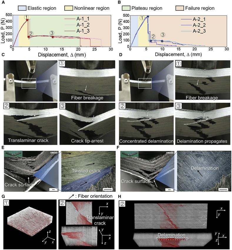
ll
     OPEN ACCESS
                                                                                             Article

of the crack driving force for a twisted crack in a Bouligand composite have demon-
strated that the resistance to cracking is significantly increased for a twisted crack
path compared to a linear (flat) crack in a homogeneous material.12,13 However, bio-
logical materials are a hierarchical assembly of architectures at multiple length
scales; their elegant and effective toughening mechanisms are thus complex. Phys-
ics-based models to explain the toughening mechanisms are far from complete,
which hinders systematic bioinspired designs for possible engineering applications.

The question that we pose in this study is whether the remarkable impact resistance
of the mantis shrimp’s dactyl club is associated with toughening mechanisms other
than those resulting from the Bouligand-type architecture and whether these fea-
tures can be made and realistically built into synthetic materials to make energy-
absorbing structures. To emulate these structures requires the fabrication of syn-
thetic materials that can mimic these structures and mechanisms. This is a chal-
lenging task, particularly with respect to finding an appropriate processing method
to fabricate nature’s complex structures. Although many advanced fabrication tech-
niques are available now,14 most are ‘‘top-down,’’ in which one starts with a large
piece of material and then processes it to a smaller scale. Nature’s design, however,
is ‘‘bottom-up,’’ in which the initial atomistic or molecular design is built up over mul-
tiple length scales into a macro-scale material. While still an immature process from
the perspective of guaranteeing the quality (rather than just the shape) of fabricated
components, additive manufacturing represents a promising array of techniques to
make bioinspired materials in the image of nature. Biomimetic helicoidal composite
materials have been three-dimensionally (3D) printed with hard-soft bi-materials,
liquid-crystal polymers, and cement-based materials so as to explore their resulting
mechanical properties.15–18 Also, thin-ply Bouligand composites with a small inter-
ply angle have been fabricated using automated tow or tape placement, with the
aim of exploring whether enhanced impact damage resistance can be obtained in
Bouligand architectures with carbon fiber (CF)-reinforced plastics.19 Similarly,
continuous-fiber reinforced composites can be easily fabricated through fused
deposition molding (FDM)-based 3D printing for any type of fiber stacking architec-
ture. In addition, voids as manufacturing defects can be derived either from gas bub-
bles by volume expansion of moisture or gaps of adjacent filaments during fiber
printing, as illustrated by Blok et al.20 and He et al.21 Due to their generally delete-
rious effects on mechanical properties, efforts are invariably made to suppress voids
in modern manufacturing techniques, such as with out-of-autoclave curing.22 How-
ever, the plastic growth of voids, which are induced during injection molding in
deformed polyamide and polypropylene matrices, have been found to trigger large
plastic deformation of the surrounding matrix, which suggests that the presence of
voids could play a role in contributing to the toughness.23,24 However, the effects of
such voids on the mechanical properties of bioinspired materials fabricated by addi-
tive manufacturing have yet to be investigated.

Dactyl clubs from Odontodactylus japonicas, a species of aggressive mantis shrimp
with a hammer-like appendage, were targeted in the present study. Morphologies
across the transverse section of the periodic region, these appendages were
observed and are shown in Figure 1A. Chitin fibers were found to be helicoidally ar-
ranged in a Bouligand-type structure with each layer rotated by a small angle a from
the layer below, which was consistent with the architecture previously reported for
the peacock mantis shrimp (O. scyllarus).7,12,13 However, a different feature was
visible, showing the presence of numerous voids randomly distributed with elliptical
shapes in the coronal section of the periodic region (Figure 1A), which we believe
may have been overlooked in previous studies.

2    Cell Reports Physical Science 1, 100109, July 22, 2020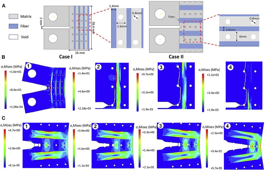
ll
                                                                                                                                    OPEN ACCESS
Article

Figure 1. Characterization of Structures
(A) Morphologies of Odontodactylus japonicas: SEM images of cross-section and coronal section in periodic region (red).
(B–F) Bioinspired composite laminates created by 3D printing.
(B) Schematic of the helicoidal fiber orientation in the bioinspired composites and the printing process.
(C) Schematic illustration of the ideally distribution pattern of voids in the printed helicoidal composites.
(D) 3D micro-CT image and a sectional view of helicoidal composites by 3D printing showing void distribution marked in red.
(E and F) Micrographs of voids in the polished sections of the helicoidal composites by 3D printing: (E) without hot pressing and (F) with hot pressing.

To mimic the microstructure of the dactyl club, in this work bioinspired helicoidal
composite laminates are fabricated using FDM-based 3D printing methods with
continuous CFs. All of the printed samples together with the fabrication defects
are carefully characterized and then tested in three-point bending and under Charpy
pendulum impact loading, with the toughening mechanisms including the Bouli-
gand-type architecture and voids carefully examined. The interlaminar stress

                                                                                            Cell Reports Physical Science 1, 100109, July 22, 2020    3
ll
     OPEN ACCESS
                                                                                                 Article

Table 1. Summary of Fabricated Samples with Different Stacking Sequences for Different Tests
 Group   Test Method    Specimen Geometry            Stacking Sequence     Dimension (mm)/
                                                                           Number of Layers

 A       Three-point    A-1 (Helicoidal 16.36 )     [0/16.36/32.72...     (96 33 13 3 3.5)/24
         bending                                     /163.6/180]S
                        A-2 (Quasi-isotropic)        [0/G45/90]3S          (96 3 13 3 3.5)/24

                        A-3 (Helicoidal 36 )         [0/36/.../144/180]S   (96 3 13 3 3.5)/24
 B       Charpy         B-1 (Helicoidal 9.47 )      [0/9.47/18.95./       (80 3 10 3 5.0)/40
         pendulum                                    170.53/180]S
                        B-2 (Quasi-isotropic)        [0/G45/90]5S          (80 3 10 3 5.0)/40
                        B-3 (Helicoidal 9.47 with   [0/9.47/18.95./       (80 3 10 3 4.4)/40
                        hot pressing)                170.53/180]S

variation within the Bouligand-type structure is analyzed based on our simulation re-
sults, and a theoretical model established to correlate the crack growth patterns with
the laminate architecture to discern the optimal design for maximum fracture resis-
tance. Furthermore, the role of the voids in fiber composites containing matrix cracks
under load is also investigated by finite element (FE) modeling to validate their
possible contribution to the toughening.

RESULTS AND DISCUSSION
Microstructural Characterization
Based on the observations of biological microstructures, we designed our synthetic
composites with a helicoidal fiber stacking sequence shown in Figure 1B; the helicoi-
dal angle in the laminates was defined as the rotation angle between two adjacent
layers. Our considered ideal patterns for the distribution of the interbead voids
from 3D printing for the composite laminates with helicoidal and quasi-isotropic
([0/G45/90]5 s) stacking sequences are given in Figure 1C. However, in the actual
printing process of the CF/PA6 filaments through the heated nozzle without any
pressure mechanism in place, voids in the PA6 matrix and at the fiber-matrix inter-
face, which could vary in size and spatial distributions, would appear because of
the lack of matrix consolidation. Two groups of samples with different helicoidal an-
gles were printed for static bending (group A) and Charpy impact tests (group B),
respectively, together with their counterparts of quasi-isotropic stacking sequences
in each group for comparison. The structural details of all printed samples are given
in Table 1. X-ray computed tomography (CT) (Figure 1D) indicated that voids,
marked in red, were distributed helicoidally, with the interbead voids concentrated
in band-like areas parallel to the fiber orientation in each single layer. With the image
in Figure 1E, the void fraction, calculated in terms of area fractions25 for composites
with a helicoidal angle of 16.36 , was measured to be 7.1%. After hot pressing, the
voids were almost eliminated, with the void fraction reduced to 1.5% (Figure 1F).

Mechanical Properties
The load-displacement curves of printed specimens under three-point bending are
shown in Figures 2A and 2B for helicoidal (group A-1) and quasi-isotropic (group A-2)
samples, respectively. For the bioinspired helicoidal composites, the load-displace-
ment curves in Figure 2A can be classified into four regions: an elastic region, a
nonlinear region, a plateau region, and a failure region. The load increased nonli-
nearly following the initial elastic region; after reaching the peak load, the curves
dropped sharply due to fiber breakage, which was apparent in the lower layers. Sub-
sequently, cracks rapidly penetrated several layers in the thickness direction before
being arrested. The helicoidal composites were observed to sustain the load (150

4     Cell Reports Physical Science 1, 100109, July 22, 2020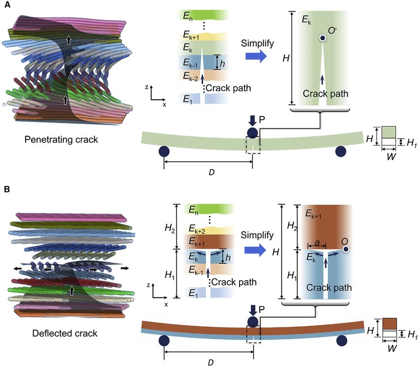
ll
                                                                                                                                   OPEN ACCESS
Article

Figure 2. Three-Point Bending Tests
(A and B) Load-displacement curves for (A) helicoidal (A-1) and (B) quasi-isotropic (A-2) composite laminate samples under three-point bending.
(C and D) Corresponding deformation history accompanied by failure modes from the side view for (C) helicoidal (A-1) and (D) quasi-isotropic (A-2)
samples, respectively.
(E and F) Micrograph observations for various crack morphologies for (E) helicoidal (A-1) and (F) quasi-isotropic (A-2) laminated samples after three-
point bending tests.
(G and H) Micro-CT images for (G) helicoidal samples (A-1) from the nonlinear and failure regions and (H) quasi-isotropic samples (A-2) are presented
with voids or crack paths highlighted in red.
The numbers in (C) and (G) correspond to those in (A), while those in (D) and (H) correspond to (B).

                                                                                           Cell Reports Physical Science 1, 100109, July 22, 2020   5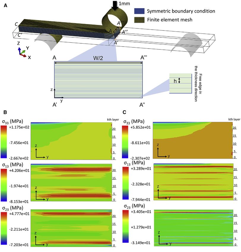
ll
OPEN ACCESS
Article
N) for a long period (5–20 mm in displacement) before they fully collapsed, where-
upon the cracks, which displayed a tortuous path, rapidly propagated through the
sample thickness. Conversely, for the quasi-isotropic (group A-2) samples, three re-
gions with no plateau region were observed in the load-displacement curves (Fig-
ure 2B). After the rapid load drop at the end of the nonlinear region, cracks again
propagated rapidly through the thickness direction with extensive delamination.
For these composites, the load-bearing capability in this failure region was dimin-
ished to essentially zero before abrupt failure.
Following testing, the fracture morphologies for different groups of samples were
examined and images are shown in Figures 2E and 2F. In addition, detailed charac-
terizations from computed X-ray micro-tomography (micro-CT) studies are also seen
in Figures 2G and 2H, where the voids within the vicinity of the fracture regions are
revealed in red. For the group A-1 helicoidal 16.36 composite laminates, while it
was difficult to discern whether matrix cracking occurred in the nonlinear region
owing to the ubiquitous presence of voids in the micro-CT images (Figure 2G),
twisted crack trajectories and delaminations could be readily identified after the first
load drop in Figures 2G and 2H, respectively.
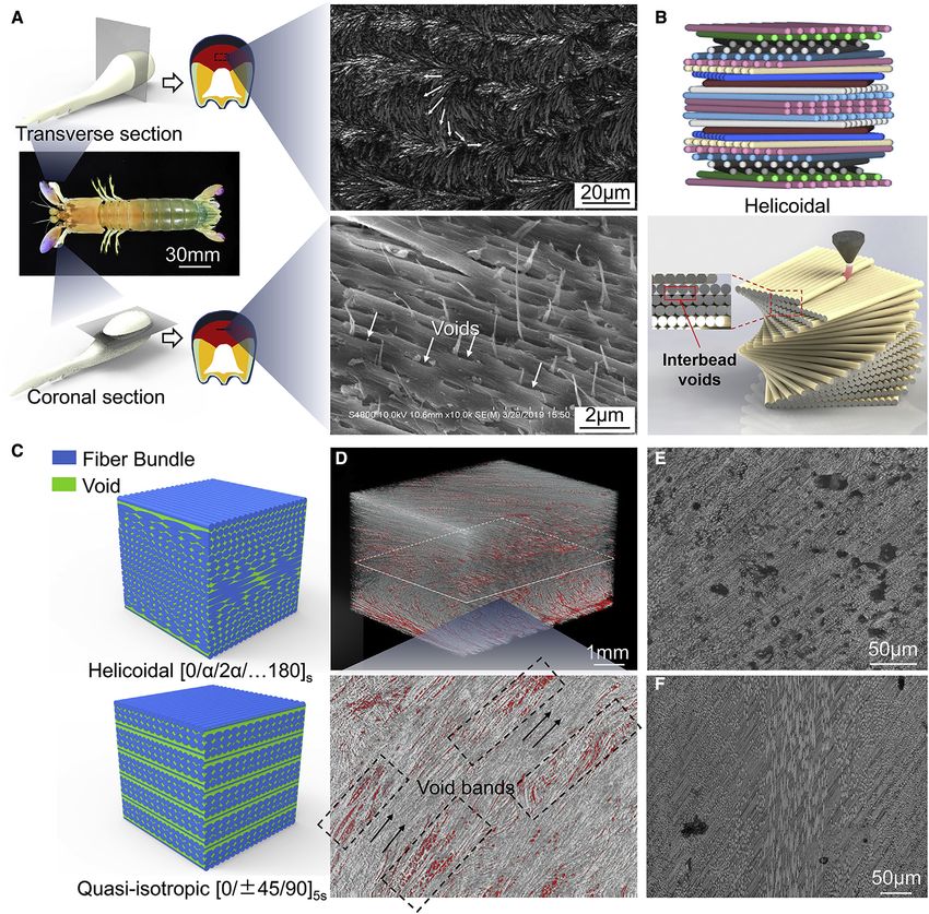
The fracture modes after the Charpy pendulum tests are shown in Figure 3. For the
3D printed helicoidal composite laminates with and without hot pressing, twisted
cracks were seen to be symmetrically distributed with respect to the neutral plane
(Figures 3B and 3D), but the crack surface was much smaller, with brittle cracks in ev-
idence after hot pressing. In contrast, extensive delaminations occurred in the
quasi-isotropic samples (Figure 3C). A higher magnification of the Figure 3B image
in Figure 3E provides more details of the nature of the twisted cracks in the helicoidal
composites. Cracked layers on crack surfaces were divided by bands, where the frac-
ture of interbead voids, sized in the range of tens of micrometers, was detected in
the matrix. However, there were no such void bands on the twisted crack surfaces
for the hot-pressed samples in group B-3 (Figure 3F). The ideal pattern for interbead
void intervals between every two fiber bundles is shown in Figure 3G. A twisted crack
in the helicoidal laminates penetrated each layer, with the crack front parallel to the
fiber orientation in that layer. These observations suggest a specific role for the in-
terbead voids to guide the tip of the twisting crack in the helicoidal composite lam-
inates to form an ideally twisted crack trajectory, as shown by the white surface in
Figure 3H. The lack of guidance from the interbead voids would result in crack
growth with low energy absorption, including the brittle fracture with a non-ideal
twisted crack path having a smaller surface area; this is typical of the helicoidal lam-
inates after hot pressing, as the brown surface exhibits schematically in Figure 3H.
However, more detailed effects on mechanical behavior, specifically due to the pres-
ence of the voids, from mere observations were difficult to discern; accordingly, to
gain better comprehension of the contribution of the voids to the toughness, a rela-
tively simple 2D FE model was developed, as discussed below.
The mechanical properties of the fabricated composite laminates were analyzed
with void fraction variations based on the above experimental results, as shown in
Figure 4A. The flexural stiffness Ef was defined in terms of the laminate width W
and height H, as Ef = ð2D 3 m =WH3 Þ, where m is the slope of the load-displacement
curve in the elastic region and D is the half-support span. The flexural strength was
calculated by sf = ð3Pm D =WH3 Þ where Pm is the peak load at failure. Compared to
their quasi-isotropic counterparts, the flexural stiffness Ef of the helicoidal 16.36
composites was >18% higher, but their flexural strength was 10% lower. The energy
absorption Ub, measured by the area under the load-displacement curves until the
6 Cell Reports Physical Science 1, 100109, July 22, 2020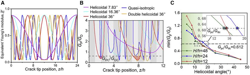
ll
                                                                                                                                    OPEN ACCESS
Article

Figure 3. Charpy Impact Tests
(A–H) (A) Observation direction; fracture modes of (B) helicoidal 9.47  composite beams (group B-1), (C) quasi-isotropic composite beams (group B-2),
and (D) helicoidal composite beams after hot pressing (group B-3) (scale bar: 100 mm); (E) microscopic observation of crack surface in (B), and fracture
through voids; (F) microscopic observation of crack surface in (D); (G) geometric model of ideal twisted crack in a helicoidal composite with interbead
voids and the exposed crack surface; and (H) a schematic comparison of crack paths in group B-1 and group B-3 (brown surface).

load dropped to 20% of the peak value, was used as an approximate estimate of the
toughness (i.e., fracture resistance). Using these Ub measurements, the helicoidal
16.36 laminates were found to possess a toughness over a factor of 2 higher than
that measured for the quasi-isotropic materials. Such an increased energy absorp-
tion of the helicoidal laminates was attributed to the unique twisting cracking
mode that provided an extrinsic toughening mechanism (crack deflection or twist)
to markedly diminish the crack-driving force (e.g., the strain energy release rate,
stress intensity factor),9,13 and therefore greatly minimize the risk of any fast-devel-
oping delamination. For the helicoidal composites with a = 36 , a mixed-mode frac-
ture was also observed with extensive twisted delamination cracks; the energy ab-
sorption of these composites was inferior to the helicoidal laminates with a =
16.36 . The mechanisms for such fractures are analyzed in more detail below.

                                                                                            Cell Reports Physical Science 1, 100109, July 22, 2020    7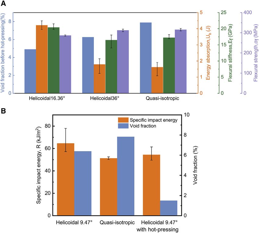
ll
      OPEN ACCESS
                                                                                                           Article

Figure 4. Comparison of Flexural and Impact Properties
(A) Comparisons of energy absorption, flexural stiffness, and flexural strength for helicoidal 16.36  ,
helicoidal 36  , and quasi-isotropic composite beams.
(B) Comparison of specific impact energy R between helicoidal and quasi-isotropic composite
laminates.
Data are represented as median, maximum, and minimum values.

The impact properties of all of the samples were calculated in terms of the specific
impact energy, R = Ui/WH, where Ui is the impact energy absorption. Values for
the helicoidal laminated composites are compared with those of the quasi-isotropic
laminates in Figure 4B. It is clear that 3D-printed helicoidal composites displayed
>25% higher specific impact energy than their quasi-isotropic counterparts, pro-
vided that they were not hot pressed. With hot pressing, the specific impact energy
R for group B-3 samples was decreased by 15.7% compared to group B-1 samples
without hot pressing; in addition, the void fraction decreased from 7.1% to 1.5%.
These results further confirm the role of voids in contributing to the impact fracture
resistance of the helicoidal laminates by locally arresting the crack growth and facil-
itating the twisting patterns of crack paths, both serving to alleviate brittle fracture.
We attempted to create voids in our composites induced by 3D printing to simulate
those observed in certain biomaterials, for example, the mantis shrimp raptorial
appendage, as we believed that the voids would contribute to the excellent impact
resistance of these helicoidal constructions.

Interlaminar Stress Analysis
For engineering composite laminates, as failure can occur readily by ply delamina-
tion, interlaminar stress analysis is often used for their architectural design. To better
understand these interlayer toughening mechanisms of Bouligand structures, the
interlaminar stresses s13, s23, and s33 between every 2 layers under 3-point bending
were estimated using finite element analysis (FEA) for a helicoidal 16.36 composite

8     Cell Reports Physical Science 1, 100109, July 22, 2020
ll
OPEN ACCESS
Article
beam. (Note that 1–3 refers to the main directions in a single ply.) To validate the
FEA used for interlaminar stress analysis, a 4-layer laminated composite [0/90]s
was conducted, as depicted in Figure S1A. The loading method, geometry, mechan-
ical properties of materials, and laminating schemes were the same as the finite dif-
ferences (FD) model of Pipes and Pagano26 and Solis et al.27. A minimum number of
6 FE nodes in the thickness direction of 1 layer was used. The FE model contained
>1.6 million elements. The resultant stresses from those studies and the present
work were compared and displayed good agreement, as shown in Figure S1B. In
addition, a convergence study was ensured.
Subsequently, a one-quarter model consisting of linear hexahedral solid elements
C3D8R in each layer was established with a locally refined mesh near the free
edge A00 -A000 , as shown in Figure 5A. Symmetrical boundary conditions and sur-
face-to-surface contact were used to improve computational efficiency, with an
imposed displacement of 1 mm. Using elastic parameters, specifically E11 = 137.9
GPa, E22 = E33 = 14.5 GPa as elastic modulus, m12 = m13 = m23 = 5.86 GPa as shear
modulus, and v12 = v13 = v23 = 0.21 as Poisson’s ratio, taken from published
work21 for our calculations, the FE method was validated on a 4-layer laminate
with a stacking sequence of [0/90/90/0] in tension by comparing the obtained inter-
laminar stress distributions with those in He et al.21 Following validation, similar cal-
culations were conducted on the composites with different laminating schemes.
Interlaminar stress distributions for s13, s23, and s33 in the area A-A0 -A00 -A000 (Fig-
ure 5A) were calculated, as shown in Figure 5B. Concentrated interlaminar tensile
stresses s33 can be found at the free edges (A00 -A000 ) of the helicoidal and quasi-
isotropic composites, which would promote tensile opening and thus delamination
at the free edge. However, interlaminar shear stresses s13 and s23 are also distrib-
uted widely along the interfaces (y direction), which can contribute to sudden
shear-dominated delamination, as reported elsewhere.28 For the helicoidal lami-
nated composites, such s13 and s23 interlaminar shear stresses concentrate near
the boundary area of the beam located between z/h = 2–5 in the lower half of the
beam, and between z/h = 20–23 in the upper half. This could trigger the twisted
crack formation in the area in between, as observed in Figure 2E. For the quasi-
isotropic laminated composites, these interlaminar shear stresses are concentrated
in multiple interfaces at z/h = 2, 6, 10 and symmetrically at z/h = 14, 18, 22, which
implies that such delaminations could occur for the composite beam at all of these
interfaces.
Theoretical Model
The fracture resistance of a composite laminate depends largely on its failure mode,
specifically, if the crack is deflected at, or penetrates through, the laminae (or
layered) regions. Accordingly, for the improved design of helicoidal composites,
one approach is to relate the failure mode to the composite micro-architecture.
To achieve this objective, we simplified the problem of crack propagation in 3D
space as a plane-strain problem with crack growth in the symmetrical mid-plane
along a path in the thickness direction (i.e., along the y direction). For the case of
a crack penetrating the layers (Figure 6A), a homogeneous 2D beam model was es-
tablished with an equivalent Young’s modulus Ek for the kth layer, where the crack is
sited. Detailed calculations of Ek are provided below. For the case of a crack deflect-
ing at the layers, the crack path is presumed to follow a straight line before encoun-
tering the interface, whereupon it deflects transversely along the interface, with a
deflection length of a on either side. We establish here a bi-material beam model,
shown in Figure 6B, which comprises two homogeneous layers with equivalent
Young’s moduli Ek and Ek+1, respectively. The equivalent Young’s modulus, Ek,
Cell Reports Physical Science 1, 100109, July 22, 2020 9ll
OPEN ACCESS
Article
Figure 5. Interlaminar Stress Analysis Based on Finite Element Method
(A–C) (A) Finite element model. Interlaminar stresses distributions in the area A-A 0 - A 00 -A 00 0 for (B) helicoidal 16.36 composites and (C) quasi-isotropic
composites: s 13 , s 23 and s 33 are the interlaminar stresses between 2 adjacent layers. Note that the number of the k th layer is marked on the right side of
the contours.
defined as the stiffness in the x direction, is analyzed for the subsequent stress cal-
culations using the Euler-Bernoulli beam theory. According to Fischer et al.,13 the
equivalent Young’s modulus varies continuously in the z direction and can be
derived in Equations 1 and 2:
E~k = 2FðzÞε2z ; (Equation 1)
.
FðqÞ = E22 F1 + F2 cos 2 q + F3 cos 4 q F4 ; (Equation 2)
10 Cell Reports Physical Science 1, 100109, July 22, 2020ll
OPEN ACCESS
Article
Figure 6. Simplification of Two Crack Propagation Scenarios
(A and B) Penetrating crack (A) and deflected crack (B).
where F~1 F
~ 4 are local elastic strain energy density items, which can be derived
from expressions in the work of Fischer et al.13 The 0 and 90 laminae have the high-
est and lowest values of their equivalent Young’s modulus, respectively. Thus, the
equivalent Young’s modulus of the laminae with other orientations must vary be-
tween these maximum and minimum values.
For the crack deflected at the lamellae, the energy release rate GD can be calculated
based on Equation 3,29 that is,
P2 1 1
GD = P P ðD aÞ2 ; (Equation 3)
8W c sub
P WH32 P H31 lH32 lH1 H2 ðH1 + H2 Þ2
where sub = 12 3 Esub , c = Ic 3 W 3 Ec , Ic = 12 + 12 + 4ðH1 + lH2 Þ , Ec =
E k 3H1 + E k + 1 3H2 Ek + 1
H , l= and Esub = Ek .
Ek
Here, H is laminate thickness, with H1, H2, and D defined in Figure 6.
Cell Reports Physical Science 1, 100109, July 22, 2020 11ll
OPEN ACCESS
Article
For the crack penetrating the lamellae, the crack tip is assumed to be in pure mode I
(tensile opening condition), with the corresponding energy release rate GP calcu-
lated from Equation 430:
K12
Gp = ; (Equation 4)
Ek
where the mode I stress intensity K1 = ð3PD =2WH3=2 Þf1 ðH1 =HÞ, P is the load in quasi-
static three-point bending, and
2 !
H1 H1 H1 H1
1:99 H 1 H 2:15 3:93 + 2:7
H H
H1
f1 = 3=2 :
H H1 H1
1+2 1
H H
Following the original idea of Gurney and Hunt31 that a crack will propagate in the
direction of the lowest load, equivalent to maximizing the entropy increase of an
isothermal system, Cherry and Harrison32 derived a general criterion for cracking
(penetrating) or splitting (deflecting) in an anisotropic medium (or bi-material), which
was also considered by Atkins and Mai.33 He and Hutchinson34 later obtained the
same criterion to determine whether the crack would penetrate through or deflect
into the interface. These conditions are:
8
>
> GP GPC
>
G Penetrating crack
D DC
: (Equation 5)
>
>
> GP < GPC Deflected crack
:
GD GDC
GPC and GDC are fracture toughness values of the lamella and interface, which can be
determined based on mode I and mode II fracture tests. As given in Equation 5, if the
ratio GP:GD drops below the fracture toughness ratio GPC:GDC, a delamination crack
occurs at the corresponding position in the z direction. The opposite is true if GP:GD
is larger than GPC:GDC, whereupon the crack will penetrate the interface.
GPC and GDC were calculated from the following expressions:
a a2
a a
rffiffiffi 1:99 1 2:15 3:93 + 2:7
2Pmax;1 D a L L L L
GPC = 3 ;
BL3=2 L a a3=2
2 1+2 1
L L
(Equation 6)
9Pmax;II 2 a2
GDC = ; (Equation 7)
16E11 B2 H3
where L, B, D, and H are the length, width, half-span, and height of the samples, and
a is the length of the notched crack. Pmax,I and Pmax,II refer to the peak load values in
the mode I and mode II tests, as shown in Figures S2C and S2D, respectively. The
tested values of GPC and GDC were 462.3 N,m1 and 755.8 N,m1, respectively.
Values of the Young’s modulus along and perpendicular to the fiber orientation
for unidirectional CF/nylon composite laminates were calibrated through compari-
son between FEA and experimental results, yielding E11 = 52 GPa, E22 = E33 =
2.334 GPa, m12 = m13 = m23 = 10.4 GPa, and v12 = v13 = v23 = 0.25.
For the helicoidal 16.36 composites, the GP/GD curves lie above the critical value
GPC/GDC; therefore, a penetrating or a twisted crack is the only expected cracking
configuration. However, the relatively higher GP/GD values around the valley
12 Cell Reports Physical Science 1, 100109, July 22, 2020ll
OPEN ACCESS
Article
Figure 7. Mechanical Properties of the Composites
(A) Equivalent Young’s modulus in thickness direction for helicoidal 7.83 , helicoidal 16.36 , helicoidal 36 , double helicoidal 36 , and quasi-isotropic
composite beams.
(B) Variation in G P/G D with position of crack tip in the thickness direction for the lamination configuration schemes above. Predicted delamination
positions are shown in shaded areas.
(C) The critical angle for the crack mode transitioning from penetrating the layers to delaminating at the matrix-layer interfaces for the helicoidal
laminated composite, with H/h ranging from 12 to 48.
between z/h = 2–5 also indicate those locations where delaminations can occur
easily due to the high interlaminar shear stress simulation results (Figure 5B). As re-
vealed by the shaded areas below the critical GPC/GDC (= 0.612) line (Figure 7B),
delamination cracks can initiate in the thickness direction twice in the helicoidal
36 composites; however, deflections will occur >5 times in the quasi-isotropic com-
posites. These results agree well with experimental observations. For the quasi-
isotropic composites, the ‘‘valleys’’ located at z/h = 2, 6, and 10 are consistent
with the interlaminar shear stress simulation results (Figure 5C).
Based on the above theoretical model, fracture modes are compared (Figure 7B) for
composites with various lamellar stacking schemes with a fixed 24 layers. These
include helicoidal composites with a = 7.83 , a = 36 , and double helicoidal com-
posites with a = 36 (i.e., stacking sequence [0/90/36/126/./180/90]s) inspired by
the microstructures of the scales of coelacanth fish.35 Only half of the samples in
the thickness direction (i.e., the first 12 layers) was considered in each case. Among
the 5 laminating schemes, delamination is only not likely to occur in the helicoidal
7.83 and 16.36 composites. The double helicoidal 36 does not exhibit delamina-
tion until the crack penetrates through one-third of the full thickness. In contrast, the
quasi-isotropic composites always exhibit the maximum quantity of delamination
cracks. In addition, the effect of the helicoidal angle a on the cracking mode, de-
picted in Figure 7C, shows that there is a critical angle of ac = 18.2 , for a major
change in the fracture configuration at H/h = 24. Helicoidal laminates with all
OPEN ACCESS
Article
Figure 8. Finite Element Modeling of Toughening Mechanisms for Voids in a Fiber Composite
(A–C) Two cases are shown for a matrix crack propagating in a composite containing voids (A). Variations in stress contours as the matrix crack
propagates, (B) perpendicular to the fibers (case I), and (C) parallel to the fibers, with the voids between them (case II).
parallel to the fibers with the voids between them (in case II). The stress contour var-
iations during crack advance are shown in Figures 8B and 8C. In case I, the crack
propagates toward the first fiber-matrix interface but deflects as the crack tip rea-
ches the first void and follows a path through the adjacent voids (Figure 8B). In
case II, the crack runs between two fibers and propagates through each void; voids
close to the crack tip expand and tend to coalesce, which triggers plastic deforma-
tion in the surrounding matrix. Accordingly, we can conclude that the collapse of
micrometer-sized voids and associated microcracking before the main twist fracture
will contribute to the impact resistance of the composite.
In conclusion, in this study, we have focused on unraveling the underlying mecha-
nisms that have perhaps been overlooked in previous research,6,13 and as such,
we have attempted to develop, using 3D printing, bioinspired impact-resistant
continuous CF-reinforced composite laminate materials in the image of the structure
of these dactyl clubs. A summary of our principal conclusions follows:
In addition to their Bouligand architecture, which is the most characteristic
feature of these biomaterials, voids were observed between polysaccharide
a-chitin and protein interfaces in the dactyl club of O. japonicas as one species
of aggressive mantis shrimp. Accordingly, helicoidal laminated composites
were designed and fabricated by continuous-fiber 3D printing technology to
mimic the periodic region of the dactyl club, with the presence of interbead voids
14 Cell Reports Physical Science 1, 100109, July 22, 2020ll
OPEN ACCESS
Article
distributed helicoidally. As seen in micro-CT imaging, the voids were concen-
trated in band-like areas parallel to fiber orientation in each single layer.
During static bending, our 3D-printed helicoidal laminates were seen to be
capable of still carrying loads after significant damage initiation and accumula-
tion; this manifested as a prolonged plateau in stress in their stress-strain curves
associated mechanistically with highly deflected, twisted cracks penetrating
through the thickness of the material. By comparison, corresponding quasi-
isotropic composite laminates fabricated from the same materials, but without
the Bouligand structure, failed abruptly, with significant delaminations between
the layers. The high specific impact energy of 3D-printed helicoidal composites
was largely lost after the laminates were subsequently hot pressed, which served
to eliminate the presence of the interbead voids. This result indicates the impor-
tant contribution of voids in generating impact toughness.
The interlaminar stress in the synthetic helicoidal composites was studied by the
FE method and compared with that of the quasi-isotropic counterparts to explain
why the helicoidal composites with their Bouligand architecture were highly resis-
tant to interface delamination. Meanwhile, a theoretical model, based on a plane-
strain hypothesis, was used to correlate the interply angle with possible crack
configurations, specifically to discern whether a crack incident on the layers
would penetrate them (as a twisted crack) or be locally arrested, causing delam-
ination along the matrix-layer interface. Such considerations were used to select
the optimal laminating scheme for fracture resistance.
To examine the toughening effect of the voids, unidirectional fiber-reinforced
composites containing matrix voids were modeled using finite-element analysis.
The voids were found to deform or to coalesce when the matrix crack propagated
perpendicular to the fibers or parallel to the fibers, with the voids between them.
Accordingly, we believe that the voids in the present study, which were intro-
duced by a lack of consolidation during printing, can contribute to toughness
by void collapse and associated microcracking. The presence of the voids also
serves to guide the fracture in the formation of an ideally twisted crack, which
acts to enhance the impact energy absorption of the helicoidal composites
extrinsically by reducing the near-tip crack-driving force through crack deflection
or twisting mechanisms.
EXPERIMENTAL PROCEDURES
Resource Availability
Lead Contact
Further information and requests for resources and reagents should be directed to
the Lead Contact, Sha Yin (shayin@buaa.edu.cn).
Materials Availability
Commercially available CF-reinforced nylon filaments were purchased directly from
Markforged. All of the filaments were printed directly without treatment.
Data and Software Availability
The authors declare that data supporting the findings of this study are available
within the article and the Supplemental Information.
3D Printing
Our bioinspired composite laminates were fabricated using a Markforged Mark Two
3D printer with pre-impregnated continuous CF/nylon (PA6) filament. In the FDM
process, the CF/PA6 filament was fused in the nozzle, extruded out, oriented along
the designed direction, and then solidified to form one unidirectional layer. After
Cell Reports Physical Science 1, 100109, July 22, 2020 15ll
OPEN ACCESS
Article
repeating layer by layer, the bioinspired composites with a designed helicoidal
stacking sequence (e.g., [0/16.36/32.72.../163.6/180]s) with helicoidal angle a =
16.36 and 24 fiber layers, were finally formed. Here, we generally call the fiber
orientation in the first layer the baseline and zero direction, and the second layer
rotated a, and the third layer another a until completing all of the lay-ups, according
to that illustrated in the square brackets. Note that the accuracy of the geometrical
dimensions and fiber orientation is best achieved with the automatic printing pro-
cedures used here instead of traditional manual lay-ups. Notched samples were
also printed similarly for toughness testing. The dimensions and fiber orientation
were shown in Figures S2A and S2B.
Hot Pressing
Following He et al.,21 we further treated our 3D-printed samples with hot pressing at
230 C and 2 MPa pressure in line as the common processing method for engineering
composites, to eliminate voids in the printed samples for comparison.
Microstructure and Failure Characterization
The structural architecture of the appendages of the dactyl club was examined with
an Olympus OLS5000 laser scanning microscope. Detailed features were addition-
ally observed by scanning electron microscopy using a Hitachi S-4800 SEM. The
printed composites were also examined with X-ray CT using a Zeiss Xradia 410 Versa
system. The failure modes for different groups of samples were observed in a Key-
ence VHX-6000 optical microscope.
Quasi-static Three-Point Bending Tests
Quasi-static three-point bending tests were performed on printed specimens in
group A to examine their mechanical properties, as shown in Figure 2A. In accor-
dance with ASTM Standard D7264/D7264M,36 the overall dimensions of the
bending samples were 96 3 13 3 3.5 mm, with a span-to-thickness ratio of 20:1.
An Instron 8801 electro servo-hydraulic testing machine was used for the bending
tests using a displacement rate of 1 mm,min1. At least three repeated tests for
each type of specimen were performed to ensure repeatability.
Charpy Impact Tests
To evaluate the dynamic impact resistance, Charpy pendulum tests were performed
flatwise on unnotched beams with an input energy of 15 J (at an initial impact velocity
of 3.81 m,s1) using a Zwick/Roell Charpy tester; a loading span of 62 mm was used,
based on British Standard BS EN ISO 179-2.37 Only group B-3 samples were treated
by hot pressing. At least five repeated tests for each kind of specimen were conduct-
ed to ensure repeatability.
Fracture Toughness Tests
Fracture toughness tests were performed on an Instron 8801 universal mechanical
testing machine at a displacement rate of 0.5 mm,min1. Single-edge notch bend
(SENB) and end-notched flexure (ENF) samples were, respectively, used for measure-
ments of the respective mode I and II fracture toughness values GPC and GDC.
Toughening Mechanism Modeling
To examine the toughening effect of voids, unidirectional fiber-reinforced compos-
ite samples with spherical matrix voids were modeled in ABAQUS with a 2D plane
strain condition for simplicity. Compact-tension (C(T)) samples with and without
voids were generated with geometries according to ASTM Standard D5045 for frac-
ture toughness testing.38 A matrix crack, 2 mm wide and tip chamfer angle 30 , was
16 Cell Reports Physical Science 1, 100109, July 22, 2020ll
OPEN ACCESS
Article
induced to propagate into a unidirectional fiber and voided matrix composite sys-
tem perpendicular to the fibers (case I) or parallel to the fibers, with the voids be-
tween them (case II). In case I, the diameter of fibers was set at 1.4 mm; in case II,
it was set at 3.6 mm, with a constant fiber fraction of 35%. Matrix voids with a diam-
eter of 0.8 mm were assumed to be uniformly distributed, with a void fraction of 7%,
which was the same as the value of the void fraction in the printed samples. A linear
tetrahedral element, CPS4R, was used, with the materials parameters summarized in
Table S1. The mesh size was refined to be 0.2 mm in the crack propagation zone and
0.4 mm in the other areas, with the overall element number of 26,164 for the 2 types
of meshed samples shown in Figure S3. All of the samples were loaded at a displace-
ment rate of 10 mm,min1.
SUPPLEMENTAL INFORMATION
Supplemental Information can be found online at https://doi.org/10.1016/j.xcrp.
2020.100109.
ACKNOWLEDGMENTS
This work was supported by the Open Research Fund Project of the State Key Lab-
oratory of Advanced Forming Technology & Equipment (SKL2019001), the Young
Elite Scientist Sponsorship Program by the China Association for Science and Tech-
nology (CAST), the National Key Research and Development Program of China
(2017YFB0103703), and the Fundamental Research Funds for the Central Univer-
sities, Beihang University.
AUTHOR CONTRIBUTIONS
S.Y., Q.H., and H.C. fabricated all of the composites, H.C. and R.Y. carried out the
mechanical testing, H.C. and D.C. performed the microscopy and computed tomog-
raphy, H.C. developed the theoretical fracture model, and R.Y. carried out the simu-
lation of the voided composites, all under the supervision of S.Y., J.X., L.Y., Y.-W.M.,
and R.O.R. S.Y., J.X., and R.O.R. wrote the manuscript with assistance from all of the
authors.
DECLARATION OF INTERESTS
The authors declare no competing interests.
Received: March 23, 2020
Revised: May 15, 2020
Accepted: June 4, 2020
Published: July 15, 2020
REFERENCES
1. Meyers, M.A., Chen, P.Y., Lin, A.Y.M., and Seki, Sheppard, L., et al. (2016). A sinusoidally 7. Weaver, J.C., Milliron, G.W., Miserez, A.,
Y. (2008). Biological materials: structure and architected helicoidal biocomposite. Adv. Evans-Lutterodt, K., Herrera, S., Gallana, I.,
mechanical properties. Prog. Mater. Sci. 53, Mater. 28, 6835–6844. Mershon, W.J., Swanson, B., Zavattieri, P.,
1–206. DiMasi, E., and Kisailus, D. (2012). The
5. Amini, S., Tadayon, M., Idapalapati, S., and stomatopod dactyl club: a formidable
2. Liu, Z., Zhang, Z., and Ritchie, R.O. (2018). On Miserez, A. (2015). The role of quasi-plasticity in damage-tolerant biological hammer. Science
the materials science of Nature’s arms race. the extreme contact damage tolerance of the 336, 1275–1280.
Adv. Mater. 30, e1705220. stomatopod dactyl club. Nat. Mater. 14,
943–950. 8. Yaraghi, N.A., and Kisailus, D. (2018).
3. Patek, S.N., Korff, W.L., and Caldwell, R.L. Biomimetic structural materials: inspiration
(2004). Biomechanics: deadly strike mechanism 6. Grunenfelder, L.K., Milliron, G., Herrera, S., from design and assembly. Annu. Rev. Phys.
of a mantis shrimp. Nature 428, 819–820. Gallana, I., Yaraghi, N., Hughes, N., Evans- Chem. 69, 23–57.
Lutterodt, K., Zavattieri, P., and Kisailus, D.
4. Yaraghi, N.A., Guarı́n-Zapata, N., (2018). Ecologically driven ultrastructural and
9. Suksangpanya, N., Yaraghi, N.A., Kisailus, D.,
Grunenfelder, L.K., Hintsala, E., Bhowmick, S., hydrodynamic designs in stomatopod cuticles.
and Zavattieri, P. (2017). Twisting cracks in
Hiller, J.M., Betts, M., Principe, E.L., Jung, J.Y., Adv. Mater. 30, 1705295.
Cell Reports Physical Science 1, 100109, July 22, 2020 17ll
OPEN ACCESS
Article
Bouligand structures. J. Mech. Behav. Biomed. resistance of helicoidal fiber structures. 28. Sun, C.T., and Chu, G.D. (1991). Reducing free
Mater. 76, 38–57. J. Mech. Behav. Biomed. Mater. 56, 57–67. edge effect on laminate strength by edge
modification. J. Compos. Mater. 25, 142–161.
10. Grunenfelder, L.K., Suksangpanya, N., Salinas, 19. Mencattelli, L., and Pinho, S.T. (2019). Realising
C., Milliron, G., Yaraghi, N., Herrera, S., Evans- bio-inspired impact damage-tolerant thin-ply 29. Qu, D., Gaganidze, E., Vaßen, R., and Aktaa, J.
Lutterodt, K., Nutt, S.R., Zavattieri, P., and CFRP Bouligand structures via promoting (2018). Determination of interface toughness of
Kisailus, D. (2014). Bio-inspired impact- diffused sub-critical helicoidal damage. functionally graded tungsten/EUROFER
resistant composites. Acta Biomater. 10, 3997– Compos. Sci. Technol. 182, 107684. multilayer at 550 C by analytical and
4008. experimental methods. Eng. Fract. Mech. 202,
20. Blok, L.G., Longana, M.L., Yu, H., and Woods, 487–499.
11. Suksangpanya, N., Yaraghi, N.A., Pipes, R.B., B.K. (2018). An investigation into 3D printing of
Kisailus, D., and Zavattieri, P. (2018). Crack 30. Nobile, L. (2000). Mixed mode crack initiation
fibre reinforced thermoplastic composites.
twisting and toughening strategies in and direction in beams with edge crack. Theor.
Addit. Manuf. 22, 176–186.
Bouligand architectures. Int. J. Solids Struct. Appl. Fract. Mech. 33, 107–116.
150, 83–106.
21. He, Q., Wang, H., Fu, K., and Ye, L. (2020). 3D 31. Gurney, C., and Hunt, J. (1967). Quasi-static
printed continuous CF/PA6 composites: crack propagation. Proc. Roy. Soc. A Math.
12. Song, Z., Ni, Y., and Cai, S. (2019). Fracture
effects of microscopic voids on mechanical Phys. Sci. A299, 508–524.
modes and hybrid toughening mechanisms in
performance. Compos. Sci. Technol. 191,
oscillated/twisted plywood structure. Acta
108077. 32. Cherry, B.W., and Harrison, N.L. (1970). Crack
Biomater. 91, 284–293.
propagation directions in anisotropic media.
13. Fischer, F.D., Kolednik, O., Predan, J., Razi, H., 22. Mehdikhani, M., Gorbatikh, L., Verpoest, I., and Fibre Sci. Technol. 2, 299–301.
and Fratzl, P. (2017). Crack driving force in Lomov, S.V. (2019). Voids in fiber-reinforced
polymer composites: a review on their 33. Atkins, A.G., and Mai, Y.-W. (1985). Elastic and
twisted plywood structures. Acta Biomater. 55,
formation, characteristics, and effects on Plastic Fracture (Ellis Horwood).
349–359.
mechanical performance. J. Compos. Mater.
53, 1579–1669. 34. He, M., and Hutchinson, J.W. (1989). Crack
14. San Ha, N., and Lu, G. (2019). A review of recent deflection at an interface between dissimilar
research on bio-inspired structures and elastic materials. Int. J. Solids Struct. 25, 1053–
materials for energy absorption applications. 23. Dasari, A., Yu, Z.Z., and Mai, Y.-W. (2007).
1067.
Compos. Part B Eng. 181, 107496. Trans-crystalline regions in the vicinity of nano-
fillers in polyamide-6. Macromolecules 40, 35. Quan, H., Yang, W., Schaible, E., Ritchie, R.O.,
15. Moini, M., Olek, J., Youngblood, J.P., Magee, 123–130. and Meyers, M.A. (2018). Novel defense
B., and Zavattieri, P.D. (2018). Additive mechanisms in the armor of the scales of the
manufacturing and performance of 24. Dasari, A., Zhang, Q.X., Yu, Z.Z., and Mai, Y.-W. ‘‘living fossil’’ coelacanth fish. Adv. Funct.
architectured cement-based materials. Adv. (2010). Toughening polypropylene and its Mater. 28, 1804237.
Mater. 30, e1802123. nanocomposites with submicrometer voids.
Macromolecules 43, 5734–5739. 36. ASTM. D7264/D7264M. ASTM standard test
16. Gantenbein, S., Masania, K., Woigk, W., method for flexural properties of polymer
Sesseg, J.P.W., Tervoort, T.A., and Studart, 25. Purslow, D. (1984). On the optical assessment matrix composite materials. https://www.astm.
A.R. (2018). Three-dimensional printing of of the void content in composite materials. org/Standards/D7264.
hierarchical liquid-crystal-polymer structures. Composites 15, 207–210.
Nature 561, 226–230. 37. British Standards Institute. BS EN ISO 179-2
26. Pipes, R.B., and Pagano, N.J. (1970). Plastics. Determination of Charpy impact
17. Yang, Y., Chen, Z., Song, X., Zhang, Z., Zhang, properties. Part 2. Instrumented impact test.
Interlaminar stresses in composite laminates
J., Shung, K.K., Zhou, Q., and Chen, Y. (2017). https://www.iso.org/obp/ui/#iso:std:iso:179:-
under uniform axial extension. J. Compos.
Biomimetic anisotropic reinforcement 2:ed-2:v1:en.
Mater. 4, 538–548.
architectures by electrically assisted
nanocomposite 3D printing. Adv. Mater. 29, 38. ASTM. ASTM D5045 - 14. Standard test
1605750. 27. Solis, A., Sánchez-Sáez, S., and Barbero, E. methods for plane-strain fracture toughness
(2018). Influence of ply orientation on free- and strain energy release rate of plastic
18. Ribbans, B., Li, Y., and Tan, T. (2016). A edge effects in laminates subjected to in-plane materials. https://www.astm.org/Standards/
bioinspired study on the interlaminar shear loads. Compos. Part B Eng. 153, 149–158. D5045.htm.
18 Cell Reports Physical Science 1, 100109, July 22, 2020You can also read