Volcano load control on dyke propagation and vent distribution: Insights from analogue modeling
←
→
Page content transcription
If your browser does not render page correctly, please read the page content below
Volcano load control on dyke propagation and vent
          distribution: Insights from analogue modeling
      M. Kervyn, G.G.J. Ernst, Benjamin van Wyk de Vries, Lucie Mathieu, P.
                                                Jacobs

     To cite this version:
    M. Kervyn, G.G.J. Ernst, Benjamin van Wyk de Vries, Lucie Mathieu, P. Jacobs. Volcano load control
    on dyke propagation and vent distribution: Insights from analogue modeling. Journal of Geophysical
    Research : Solid Earth, American Geophysical Union, 2009, 114, pp.B03401. �10.1029/2008JB005653�.
    �hal-00454372�

                                 HAL Id: hal-00454372
                https://hal.archives-ouvertes.fr/hal-00454372
                                    Submitted on 12 Aug 2021

    HAL is a multi-disciplinary open access            L’archive ouverte pluridisciplinaire HAL, est
archive for the deposit and dissemination of sci- destinée au dépôt et à la diffusion de documents
entific research documents, whether they are pub- scientifiques de niveau recherche, publiés ou non,
lished or not. The documents may come from émanant des établissements d’enseignement et de
teaching and research institutions in France or recherche français ou étrangers, des laboratoires
abroad, or from public or private research centers. publics ou privés.
                                              Copyright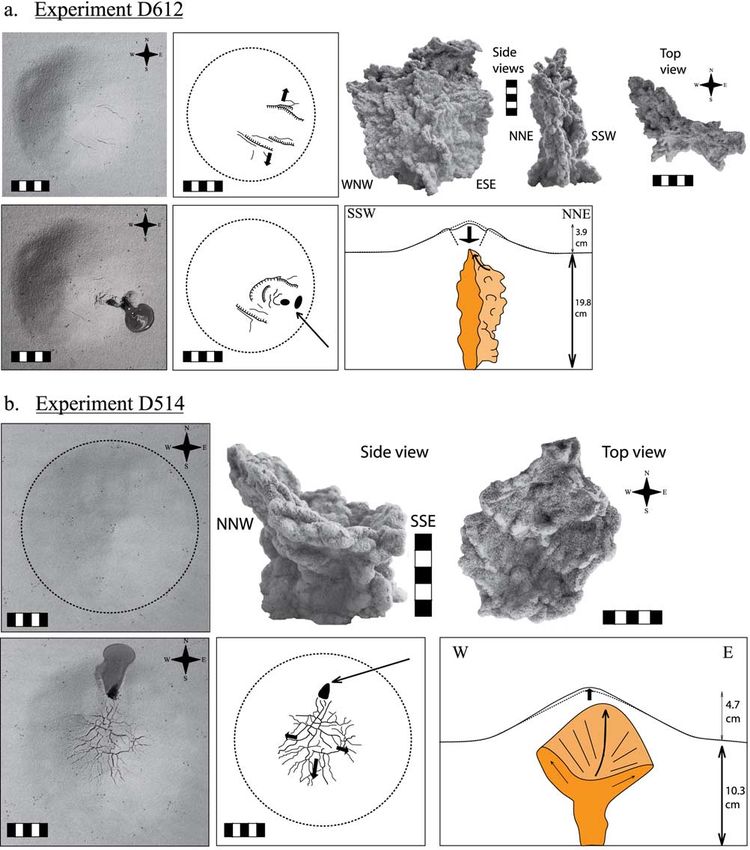
JOURNAL OF GEOPHYSICAL RESEARCH, VOL. 114, B03401, doi:10.1029/2008JB005653, 2009

Volcano load control on dyke propagation and vent distribution:
Insights from analogue modeling
M. Kervyn,1 G. G. J. Ernst,1 B. van Wyk de Vries,2 L. Mathieu,2,3 and P. Jacobs1
Received 25 February 2008; revised 17 December 2008; accepted 9 January 2009; published 3 March 2009.

[1] The spatial distribution of eruptive vents around volcanoes can be complex and
evolve as a volcano grows. Observations of vent distribution at contrasting volcanoes,
from scoria cones to large shields, show that peripheral eruptive vents concentrate close to
the volcano base. We use analogue experiments to explore the control of volcano load on
magma ascent and on vent location. Results show that the local loading stress field favors
eruption of rising magma away from the volcano summit if a central conduit is not
established or is blocked. Two sets of scaled experiments are developed with contrasting
rheological properties to analyze similarities and differences in simulated magma rise
below a volcano: (1) Golden syrup (magma analogue) is injected into a sand-plaster mixed
layer (crust analogue) under a cone; (2) water or air (magma analogues) is injected into
gelatin under a sand cone. Rising dykes approaching the cone stress field are stopped
by the load compressive stress. With continued intrusion, dyke overpressure builds up;
dykes extend laterally until their tips are able to rise vertically again and to erupt in the
flank or at the base of the volcano. Lateral offset of the extrusion point relative to the
edifice summit depends on substratum thickness, volcano slope, and dyke overpressure.
The 3D geometry of Golden syrup intrusions varies with experimental parameters from
cylindrical conduits to dyke and sill complexes. Experimental results are compared
with illustrative field cases and with previously published numerical models. This
comparison enables applications and limitations of the analogue models to be highlighted
and allows us to propose a conceptual model for the evolution of vent distribution with
volcano growth.
Citation: Kervyn, M., G. G. J. Ernst, B. van Wyk de Vries, L. Mathieu, and P. Jacobs (2009), Volcano load control on dyke
propagation and vent distribution: Insights from analogue modeling, J. Geophys. Res., 114, B03401, doi:10.1029/2008JB005653.

1. Introduction                                                            tures and direction, magma chamber location and size,
                                                                           magma composition [e.g., Bacon, 1985; Connor et al.,
  [2] A volcano grows by successive eruptions from a
                                                                           1992; Fialko and Rubin, 1999; Mazzarini and D’Orazio,
central vent and/or from vents on the flanks or around the
                                                                           2003; Corazzato and Tibaldi, 2006]. Vent distribution in
base. It can also grow endogenously by intrusion. Intrusions
                                                                           turn influences volcano growth and morphology. Docu-
contribute to edifice construction in a complex way. They
                                                                           menting and identifying factors controlling vent distribution
can add volume [Annen et al., 2001], raise slopes, alter load
                                                                           can provide insights into controls on magma plumbing.
distribution or cause spreading and collapse. Also, they can
                                                                             [4] It is common to find peripheral vents or to observe
deform edifices, changing the stress distribution, and thus
                                                                           eruptions focusing close to a volcano base or at a marked
the boundary conditions for future intrusions and ultimately
                                                                           break-in-slope (BIS) on the lower flanks [e.g., Poland et al.,
eruptions [e.g., Walter and Amelung, 2006].
                                                                           2008]. The relationship between topography and vent
  [3] The distribution of peripheral vents can be complex
                                                                           location can be documented at many volcanoes using
and evolve through time. It is controlled by interaction of
                                                                           remote sensing topographic data. However, the process
regional and local factors: i.e., regional and local stress
                                                                           leading to preferential vent opening away from the volcano
fields, regional structures, volcano shape, spreading struc-
                                                                           summit and close to its base has been little discussed
                                                                           [Shteynberg and Solovyev, 1976; Fialko and Rubin, 1999;
    1                                                                      Pinel and Jaupart, 2004b; Gaffney and Damjanac, 2006].
      Mercator and Ortelius Research Centre for Eruption Dynamics,
Department of Geology and Soil Sciences, Ghent University, Gent,             [5] Numerous dynamic models for dyke (i.e., liquid-filled
Belgium.                                                                   fracture) propagation assuming a homogeneous half-space
    2
      Laboratoire Magma et Volcans, Université Blaise Pascal, Clermont-   have been proposed [Johnson, 1970; Pollard, 1973, 1987;
Ferrand, France.                                                           Dahm, 2000; Menand and Tait, 2002, and references
    3
      Volcanic and Magmatic Processes Research Group, Trinity College
Dublin, Dublin, Ireland.                                                   therein]. It has been proposed that dyke propagation direc-
                                                                           tion is mainly controlled by regional stress orientation,
Copyright 2009 by the American Geophysical Union.                          presence of planar discontinuities in the host rock, or
0148-0227/09/2008JB005653$09.00

                                                                    B03401                                                        1 of 26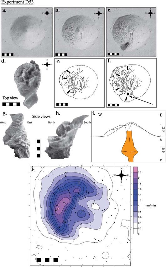
B03401                   KERVYN ET AL.: VOLCANO LOAD CONTROL ON DYKE PROPAGATION                                          B03401

changes in host rock rheological properties [e.g., Pollard,       [Mathieu et al., 2008]. Here the main difference is that the
1973]. Dyke propagation in the crust or within volcanic           effect of edifice load is now considered.
constructs has also been studied with analogue modeling,            [9] To predict propagation and outbreak location before a
using liquid injection into gelatin [Pollard, 1973; Hyndman       dyke reaches the surface, it is important to understand
and Alt, 1987; Menand and Tait, 2002; Kavanagh et al.,            processes controlling dyke initiation, propagation in the
2006; Rivalta and Dahm, 2006, and references therein].            crust or within a volcanic edifice, and interaction with the
Some field studies are available to evaluate results from         surrounding rock. The objective of this paper is to illustrate
numerical and experimental models [Walker, 1993, 1995,            and analyze volcano load control upon dyke ascent in the
1999; Gudmundsson, 2002; Klausen, 2006; Poland et al.,            upper crust and upon outbreak location. Experiments sim-
2008]. However, the 2D nature of field outcrops limits the        ulate dykes ascending from a deep source, below a homog-
ability to reconstruct the 3D shape of subvolcanic intru-         enous circular cone without any pre-established structure
sions. 3D seismic observations has recently shown some            (e.g., conduit, rift zone, dyke swarm) controlling magma
new insights into the complex shape of intrusive bodies, but      propagation. Attention is paid to scaling experiments for
with limited success for dykes [e.g., Thomson, 2007].             basalt/andesite magma viscosity, but we expect results to be
  [6] Some work has been dedicated to the propagation of          valid for a wider viscosity range.
dykes approaching volcanic constructs. Pinel and Jaupart
[2000, 2004b] developed a 2D numerical model predicting           2. Vent Concentration at a Volcano Base
that ascending dykes can be blocked underneath high
                                                                  2.1. Stratocones and Long-Lasting Scoria Cones
volcanoes (i.e., cone height 4 km for shields and 2 km
for stratovolcanoes). Edifice load causes magma storage at          [10] The geological evolution and vent distribution at
depth, or, if magma is of sufficiently low density, it favors     Concepción, Nicaragua, is presented by van Wyk de Vries
lateral dyke propagation and extrusion at the volcano base.       [1993] and Borgia and van Wyk de Vries [2003]. This
Gaffney and Damjanac [2006] numerically modeled effects           typical stratovolcano is mostly built through central erup-
from topography on a dyke rising under a ridge adjacent to a      tions, but about 20 peripheral vents (e.g., scoria cones, tuff
lowland. In this model, dykes tend to erupt in lower areas,       rings and lava domes) are located between 2.5 and 7 km from
mostly because of the geometric effect of topography and,         the summit (Figure 1). Peripheral vents to the E and W are
to a lesser extent, to the lateral confining stresses from the    associated with relatively early stages of volcano growth.
ridge. These model predictions have not yet been evaluated        They are located on flat terrains, at 200– 400 m a.s.l., in
experimentally. In this paper, experimental results are pre-      association with a circular topographic rise around the
sented to evaluate the hypothesis that edifice load affects       volcano base, interpreted to be a structure caused by volcano
magma ascent as well as vent outbreak spatial distribution.       flexure. Other peripheral vents are located on the lower flanks
  [7] Previous gelatin models have documented that stress         (i.e., slope 20° to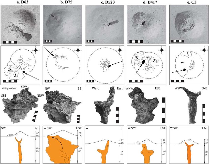
B03401                   KERVYN ET AL.: VOLCANO LOAD CONTROL ON DYKE PROPAGATION                                       B03401

         Figure 1. Vent distribution at Concepción volcano, Nicaragua. (a) Shaded relief and structural features;
         (b) slope angle; (c) north – south topographic profile along dashed line in Figure 1b. Arrows indicate the
         location of vents, including several at the cone base. Old domes (circles) and Holocene cones (triangles)
         along a pronounced north – south rift zone are all located on the lower volcano slopes (adapted from the
         works of van Wyk de Vries [1993] and Borgia and van Wyk de Vries [2003]).

  [13] The 2000 seismic/volcanic crisis at Miyakejima,           distribution at actively growing Hawaiian shields is mostly
Japan, also provided evidence for preferential dyke outbreak     limited to well-defined rift zones (e.g., Kilauea, Mauna Loa)
at the volcano base [Kaneko et al., 2005]. The first eruption    as dykes intrude laterally from a shallow magma reservoir
stage was a lateral dyke intrusion causing an earthquake         [Decker, 1987; Walker, 1990, 1999]. The end of shield
swarm propagating 30 km from Miyakejima. The dyke                building is marked by a decrease in magma supply rate and
breached the surface at the volcano base, causing a subma-       by cooling of the high-level magma chamber [Moore and
rine eruption [Kaneko et al., 2005]. A similar lateral dyke      Clague, 1992] only allowing eruptions of small, separate
injection associated with peripheral eruption and central        magma batches. This results in a scatter of 300 vents on the
caldera subsidence was also inferred for the 1912 Novarupta      flanks and at the base of Mauna Kea’s upper steep flanks
(Katmai) eruption [Hildreth and Fierstein, 2000].                (Figure 3) [Mac Donald, 1945; Porter, 1972]. About half of
                                                                 these vents are located within 3 broad and short rift zones in
2.2. Shield Volcanoes                                            the W, NE and SSE upper steep flanks. 40% of the vents,
  [14] The large oceanic Galapagos shields (e.g., Fernan-        outside or within rift zones, are located at or beyond the
dina, Cerro Azul) display an illustrative vent distribution      base of the steep upper flanks, where slopes change abruptly
related to topography [e.g., Chadwick and Dietrich, 1995;        from >15° to 15°) and more          steep shields such as Mount Etna (Italy) or Nyiragongo
gentle lower flanks (
B03401 KERVYN ET AL.: VOLCANO LOAD CONTROL ON DYKE PROPAGATION B03401
Figure 2. Vent distribution at Cerro Negro, Nicaragua. (a) Contour lines (10 m) with location of vents
from recent eruptions (adapted from the work of McNight [1995]); (b) north – south topographic profile
along dashed line in Figure 2a. Arrows indicate the location of vents, including several at the cone base.
examples however highlight that peripheral vents are often the volcano summit (Figure 4). This is investigated and
found far away from the volcano summit, beyond the evaluated with the analogue models presented hereafter. It
transition from steep upper flanks to more gently sloping should be noted that the change in slope gradient can often
lower flanks. Similar examples can be found from many be attributed to a different types of: (1) volcanic deposits
other Holocene or historically active volcanoes [Simkin and (i.e., pyroclastics versus lava) or (2) deposition dynamics
Siebert, 1994] with diverse shapes and sizes. Although we (i.e., flow versus fallout). This implies that the topographic
do not argue that the same processes of dyke propagation BIS is often associated with a lithological boundary that can
act in the same way at these different scales, these obser- also affect dyke propagation. In order to isolate the effect of
vations suggest that the local stress field directly below and edifice loading from purely lithological effects, the litho-
within volcanic edifices favors dyke propagation away from
Figure 3. Vent distribution at Mauna Kea, Hawaii. (a) Slope map; (b) map of the second derivative of the elevation at
750-m spatial resolution, highlighting with darker colors the places with rapid changes in slope angle; (c) north –south
topographic profile along dashed line in Figure 3b. Arrows indicate the location of vents, including several at the cone base.
In addition to 3 rift zones, vents are located at the base of the steep upper flanks and further downslope (within ellipses in
Figure 3a).
4 of 26B03401 KERVYN ET AL.: VOLCANO LOAD CONTROL ON DYKE PROPAGATION B03401
Figure 3
5 of 26B03401 KERVYN ET AL.: VOLCANO LOAD CONTROL ON DYKE PROPAGATION B03401
Figure 4. Conceptual representation of the s1 orientation and of the isobar lines in the substratum and
in a volcanic cone based on Dieterich [1988] and van Wyk de Vries and Matela [1998]. Dykes would
generally propagate perpendicularly to the least principal stress and parallel to orientations of s1 and s2.
The stress distribution within a conical edifice will tend to focus dykes toward the central axis. On the
other hand, the pressure gradient below the volcano’s load can favor lateral dyke propagation toward
lower confining pressure so that dykes would tend to migrate out from under the volcano [van Wyk de
Vries, 1993].
logical boundary is not simulated in the presented analogue (t 0 100 Pa). Models simulate stratocones that have a bulk
models. cohesion of 106 –108 Pa, the approximate cohesion of fresh
unfractured rock (Table 1). Test experiments showed that
3. Dyke Propagation in Granular Material varying cohesion from 25 to 150 Pa, by varying the amount
of plaster (from 5 to 40 wt%), did not significantly affect
3.1. Analogue Materials and Scaling
intrusion morphology, except that higher cohesion produced
[18] Fine granular material (i.e., a sand and plaster slightly thinner, better-scaled intrusions. The analogue
mixture) was used as analogue for upper crust country granular mixture has an internal friction angle comparable
rocks and for the volcanic cone. Golden syrup (GS) at to that for granular materials at volcanoes (30 – 40°).
room temperature (20 – 25°C) was used as magma analogue. [19] GS, the magma analogue, is a Newtonian fluid
For similarity between the model and nature, the geometric, simulating dyke propagation in a brittle medium. It
dynamic, and time parameters of the model (Table 1) must approaches the required scaling for viscosity (m) and time
be scaled [Ramberg, 1981; Merle and Borgia, 1996; Don- (t) to model basalt to andesite magma propagating in the
nadieu and Merle, 1998]. At the volcano scale, as an shallow crust below a volcanic edifice. As it is a Newtonian
approximation, the stress ratio between nature and models, fluid, time and viscosity ratios can be related to the stress
s*, can be estimated from ratio, with equation (2)
s* ¼ r* g* h* ð1Þ 1
s* m* ð2Þ
t*
where r*, g* and h* are the model/nature ratios for the
density, gravitational acceleration, and height of the where m* and t* are the model/nature ratios for viscosity and
volcanic cone, respectively. This calculation yields a stress time. Combining equations (1) and (2) yields equation (3)
ratio of 106 – 104 (Table 1). Hence an analogue volcano
should be 104 – 106 times mechanically weaker than a real
mmodel
volcano. A mixture of sand (250 mm median grain size) mnature ¼ tnature ð3Þ
with 30 wt% plaster (i.e., 100 mm) was used in the model tmodel r* g* h*
6 of 26B03401 KERVYN ET AL.: VOLCANO LOAD CONTROL ON DYKE PROPAGATION B03401
and Keating [2007]; [11] Valentine and Keating [2007]; [12] Gaffney and Damjanac [2006]; [13] Jaeger and Cook [1971]; [14] Spera [2000]; [15] Pinel and Jaupart [2004a]; [16] Battaglia and Bachèlery [2003].
Following experiment scaling
Typical range of values for scoria cones to oceanic shields are given and used to estimate key dimensionless parameters in Table 2. References: [1] Shteynberg and Solovyev [1976]; [2] Francis and Oppenheimer
[2003]; [3] Pinel and Jaupart [2000]; [4] Pinel and Jaupart [2004b]; [5] Rowland and Garbeil [2000]; [6] Walker [1995]; [7] Klausen [2006]; [8] Valentine and Krogh [2006]; [9] Poland et al. [2008]; [10] Valentine
Using a 104 height ratio, 0.55 density ratio, 0.01 – 1 time
[3], [6], [7], [8], [9], [10]
ratio and 70 Pa s analogue magma viscosity (GS viscosity,
Source of Data
[3], [8], [9], [10], [11]
Table 1), equation (3) generates a natural magma viscosity
of the order of 106 –108 Pa s. This is higher than the
[1], [3], [4], [12]
Scaling with Rco
[1], [2], [3], [4] expected viscosity for basalt magmas. Experiments ap-
[3], [15], [16]
[3], [4], [14]
[3], [4], [15]
[3], [4], [15]
proach the adequate scaling for andesite dykes, or crystal-
[1], [13]
[3], [14]
rich basalt magma, rising under a low-relief volcano (i.e.,
[3], [5]
cone height 1 103
or from a shallow magma reservoir feeding dykes to an
5 102 – 2 103
5 103 – 5 107
1 103 – 3 104
2 106 – 1 107
Nature
Range
overlying volcano.
[20] The system variability is accounted for by 11 dimen-
2150 – 2700
2300 – 2700
0 – 3 104
200 – 4000
104 – 102
0.25 – 10
102 – 106
106 – 107
sionless numbers (Table 2), derived using the P-Bucking-
30 – 40°
ham theorem [Middleton and Wilcock, 1994]. P1 to P5
Table 1. List of Parameters Identified as Potential Controlling Factors on Dyke Propagation Under a Volcano Loada
characterize the system geometry on which the analysis will
focus, as this study aims to identify the effect of volcano
5 102 – 1 104
size, slope and substratum thickness upon dyke propaga-
tion. Dimensional analysis shows reasonable matching
Model
Range
1350 – 1500
1200 – 1400
103 – 102
108 – 107
0.04 – 0.13
0.05 – 0.02
between model and nature values (Table 2). Densities,
0.01 – 0.1
0.05 – 0.2
102 – 104
30 – 40°
cohesion, gravitational acceleration, viscosity and internal
0 – 0.1
100
friction angle can be taken as constant as long as the same
70
granular material and intrusion fluid are used. Dimension-
less numbers for dynamical parameters, i.e., intrusion rate
Model/Nature
5 105
2 105
2 103
2 105
5 107
(P10) and dyke overpressure (P11), are also consistent from
Ratio
7.103
nature to models although models simulate the upper range
104
104
105
103
102
0.60
0.55
of natural values. Intrusion rate is varied in experimental
1
1
conditions by only one order of magnitude in order to test
the sensitivity of the system to this dynamic parameter. The
Nature Reference
ratio of dyke width to dyke length is only approximatively
5 103
5 103
5 106
2 105
30 – 40°
scaled: experimental dykes tend to be one order of magni-
Value
2400
1000
2400
101
9.81
tude thicker than natural examples because of intrusion
103
103
107
104
1
thickening at the end of an experiment by interaction with
the surrounding granular material.
[21] As the analogue experiments are not closely scaled
Model Reference
for low-viscosity mafic dykes caution is required when
2 103
5 108
interpreting observations. As dykes are relatively thick
5 103
2 103
30 – 40°
Value
and emplaced rapidly, observed deformation in experiments
1425
1300
0.05
9.81
100
0.1
0.1
0.1
0.1
70
will be faster, more extensive and of larger scale than
expected in large natural volcanoes. The observed defor-
mation is probably representative of that which affects a
Intrusion dynamic viscosity
poorly coherent, 500-m-high volcanic cone. The general
Substratum/Cone cohesion
Gravitational acceleration
Substratum/Cone density
Internal angle of friction
deformation pattern observed in experiments however
point-cone summit
Substratum thickness
might still provide valuable insights for a larger set of
Definition
Dyke overpressure
Distance extrusion
Intrusion density
natural cases. The expectation from scaling considerations
Intrusion rate
is that the thicker experimental intrusions and the resulting
Dyke length
Cone height
Cone radius
Dyke width
surface deformation could be considered equivalent to the
intrusion and deformation generated in nature by more than
Time
one similar intrusive event. The fact that in nature vent
distributions are similar for small to large volcanoes (i.e.,
Parameter
the relationship is scale independent) means that correct
Hco
DW
DP
Ths
Rco
modeling of small volcanoes should also provide a correct
Dx
rco
DL
t0
rI
F
m
T
g
f
a
analogue for larger volcanoes.
7 of 26B03401 KERVYN ET AL.: VOLCANO LOAD CONTROL ON DYKE PROPAGATION B03401
Table 2. List of Dimensionless Parameters Identified and Used in the Present Studya
Dimensionless Number Definition Description Models Nature
P1 Hco/Rco Volcano cone aspect ratio 0.2 – 0.75 0.1 – 0.6
P2 Rco/Ths Edifice radius/Substratum thickness 0.3 – 2.5 0.5 – 10
P3 DW/DL Dyke aspect ratio 101 – 102 102 – 104
P4 DL/Rco Dyke length/cone radius ratio 0.1 – 1 0.1 – 1
P5 Dx/Rco Dimensionless extrusion outbreak position 0–1 0–1
P6 ri/rco Magma/granular material density contrast 0.8 – 0.95 0.85 – 1
P7 t 0/(Ths g rco) Cohesion/stress ratio 5.102 2.101
P8 T2 g/Ths Dimensionless intrusion duration 107 – 109 105 – 1010
P9 (rI Ths d)/(T m) Reynolds number of intruded fluidb 105 101 – 105
P10 f T/Ths3 Dimensionless intrusion rate 5.102 – 101 106 – 101
P11 DP/(Ths g rco) Dimensionless dyke overpressure 0.1 – 5 101
a
See Table 1 for range of values used in ratio estimation.
b
Where d is the diameter of the intrusion tube for experiments.
3.2. Experimental Setup ized by many nascent lobes which record the shear motion
[22] Experiments were designed to investigate the 3D during dyke propagation. The upper tip of the dyke is often
vertical propagation of a dyke approaching a conical vol- formed by several diverging or en-echelon lobes. Each
cano, within 1 –2 km of the cone base. The setup, originally intrusive sheet is several cm long ( 15 cm) and steep volcanoes
distributed over the model surface (i.e., using PointCatcher, (P1 > 0.6) that dykes can erupt at the cone base. This is
software written by M.R. James). Table 3 details the experi- confirmed by Figure 6b that shows that low values of P2,
mental conditions. Key results from the 78 experiments are the cone radius to substratum thickness ratio, lead to a
described hereafter and illustrated on Figures 6 – 10. greater extrusion offset, especially for steep cones. Figure 6c
shows a similar trend for the effect of P4 (dyke length to
3.3. Experimental Results cone radius ratio). On average, shorter dykes do not reach
3.3.1. General Intrusions’ Morphology the cone base, irrespective of the dyke initiation depth.
[24] In a typical experiment, GS injection into granular Longer dykes break out at the base only if the dyke was
material forms one or several diverging vertical to subhor- initiated at sufficient depth. The relative intrusion rate (P10)
izontal planar sheets, 1 cm in thickness. Intrusions have a and the relative overpressure (P11) also show negative
bulbous surface texture with surface irregularities of the correlations with the outbreak offset. These parameters are
order of a few millimeters, as described by Mathieu et al. strongly correlated with the geometric ratios, especially P2,
[2008]. The intrusion lateral and upper edges are character- and thus display similar trends.
8 of 26B03401 KERVYN ET AL.: VOLCANO LOAD CONTROL ON DYKE PROPAGATION B03401
Figure 5. (a) Sketch of the experimental setup of Golden syrup intrusion into a box of fine granular
material with indication of main experimental parameters. (b) Sketch of the setup used for injection of
dyed water into a tank filled with gelatin.
9 of 26Table 3. Sand-Box Experimentsa
Experiment Time Ths Rco Hco Intrusion Rate DP Intrusion Magma Lateral
B03401
No. (min) (cm) (cm) (cm) (cm3/s) (Pa) P1 Hco/Rco P2 Rco/Ths P3 DL/DW P4 DL/Rco P5 Dx/Rco P9 106 Shape Stalling Propagation
D31 4 5.0 5.3 3.4 0.09 4940 0.64 1.06 0.10 1.13 0.79 61.9 Dyke and sill V V
complex + chamber
D32 11 6.4 5.2 3.4 0.07 80 0.65 0.81 0.03 1.06 0.58 28.8 Near-cylindrical conduit V
D33 34 5.2 5.3 3.8 0.01 1920 0.72 1.01 0.09 1.03 0.67 7.6 Dyke and sill complex V V
D34 12 5.2 8.8 5.2 0.04 3930 0.59 1.68 0.02 0.51 0.16 21.5 Deep cup-shaped
D35 25 5.6 8.4 5.6 0.03 1240 0.67 1.50 0.15 0.62 0.44 11.1 Deep cup-shaped V
D36 5 5.3 9.3 6.0 0.13 3250 0.65 1.75 0.10 0.32 0.24 52.5 Near-cylindrical conduit
D37 40 5.4 12.5 8.5 0.06 2490 0.68 2.31 0.20 0.40 0.04 6.7 Dyke and sill V
complex + chamber
D38 44 5.1 13.2 9.6 0.03 1780 0.73 2.58 0.04 0.52 0.21 5.7 Near-cylindrical conduit
D41 21 5.3 13.0 9.3 0.14 3260 0.72 2.45 0.08 0.65 0.26 12.5 Dyke and sill V
complex + chamber
D42 29 5.3 4.8 1.7 0.02 2910 0.36 0.90 0.09 0.95 0.59 9.1 Dyke and sill V
complex + chamber
D43 4.5 5.0 5.2 1.9 0.13 3900 0.36 1.04 0.44 0.87 0.10 55.0 Near-cylindrical V
conduit + chamber
D44 22 5.0 8.8 3.5 0.04 1760 0.40 1.75 0.23 0.46 0.03 11.3 Dyke and sill complex V
D45 9 5.9 9.0 2.8 0.09 4180 0.31 1.53 0.28 0.28 0.11 32.5 Dyke and sill V
complex + chamber
D46 35 5.7 13.0 4.9 0.03 2130 0.38 2.28 0.10 0.52 0.38 8.1 Dyke and sill complex V V
D47 14 5.0 13.0 4.3 0.08 1830 0.33 2.60 0.07 0.23 0.23 17.7 Dyke and sill V V
complex + chamber
D48 11 5.0 12.8 4.8 0.11 2790 0.38 2.56 0.15 0.16 0.25 22.5 Deep cup-shaped
D49 35 5.4 13.1 2.4 0.02 2030 0.18 2.43 0.05 0.31 0.11 7.6 Dyke
D410 6 5.2 13.2 2.3 0.06 3270 0.17 2.54 0.20 0.15 0.09 42.9 Deep cup-shaped
10 of 26
D411 81 5.3 12.3 2.3 0.01 2050 0.19 2.33 0.12 0.14 0.03 3.2 Dyke + deep cup-shaped V
D412 93 5.3 9.5 1.8 0.01 1930 0.19 1.79 0.50 0.11 0.13 2.8 Near-cylindrical conduit
D413 16 5.1 8.5 2.0 0.04 2000 0.24 1.67 0.08 0.56 0.33 15.8 Dyke and sill complex V V
D414 10 5.4 8.3 1.9 0.07 2970 0.22 1.53 0.10 0.24 0.17 26.7 Deep cup-shaped + chamber V
D415 25 10.1 5.6 3.5 0.07 2110 0.62 0.55 0.25 0.50 0.75 20.0 Deep cup-shaped V
D416 25 10.2 4.8 3.4 0.02 1790 0.71 0.47 0.11 0.38 0.42 20.2 Dyke + near-cylindrical
conduit
D417 46 10.3 4.6 3.2 0.02 1340 0.70 0.45 0.07 0.65 0.52 11.0 Dyke and sill V
complex + chamber
D51 35 10.1 8.2 5.0 0.06 2250 0.61 0.82 0.09 0.67 0.65 14.2 Deep cup-shaped V
D52 52 10.1 8.5 5.8 0.03 1640 0.68 0.84 0.04 0.94 0.55 9.6 Dyke and sill complex V V
D53 31 10.0 8.4 5.8 0.08 3850 0.69 0.84 0.11 0.44 0.70 16.0 Near-cylindrical V V
conduit + chamber
H5 60 9.0 9.3 5.0 0.04 2850 0.54 1.03 0.08 0.65 0.54 7.4 Dyke V
KERVYN ET AL.: VOLCANO LOAD CONTROL ON DYKE PROPAGATION
D54 105 10.4 12.4 7.8 0.02 2860 0.63 1.19 0.04 0.45 0.11 4.9 Dyke
D55 25 10.3 12.4 8.1 0.10 2510 0.65 1.21 0.07 0.36 0.37 20.3 Dyke V
D56 75 10.1 12.2 7.8 0.02 4140 0.64 1.21 0.05 0.49 0.63 6.7 Dyke and sill V V
complex + chamber
D57 60 10.2 5.7 2.1 0.02 4690 0.37 0.56 0.15 0.35 0.46 8.4 Dyke and sill V
complex + chamber
D59 26 10.1 5.1 2.0 0.08 4390 0.38 0.50 0.07 0.53 0.65 19.2 Deep cup-shaped + chamber V V
D510 101 10.1 5.3 2.1 0.01 2820 0.40 0.52 0.14 0.42 0.27 5.0 Deep cup-shaped V V
D511 19 10.1 8.0 2.8 0.09 3650 0.35 0.80 0.21 0.30 0.48 26.2 Dyke and sill complex V V
D512 57 10.1 8.3 3.0 0.02 2670 0.36 0.82 0.13 0.38 0.33 8.8 Deep cup-shaped + chamber V V
D513 15 10.2 12.9 4.7 0.13 1450 0.36 1.27 0.47 0.23 0.02 33.5 Near-cylindrical conduit
B03401B03401
Table 3. (continued)
Experiment Time Ths Rco Hco Intrusion Rate DP Intrusion Magma Lateral
No. (min) (cm) (cm) (cm) (cm3/s) (Pa) P1 Hco/Rco P2 Rco/Ths P3 DL/DW P4 DL/Rco P5 Dx/Rco P9 106 Shape Stalling Propagation
D514 59 10.0 12.8 4.8 0.04 1220 0.38 1.28 0.30 0.18 0.50 8.4 Deep cup-shaped V V
D515 27 10.3 12.5 4.7 0.07 1550 0.38 1.21 0.11 0.28 0.32 18.9 Near-cylindrical conduit
D516 28 10.1 8.8 2.0 0.05 860 0.23 0.87 0.22 0.26 0.27 17.9 Dyke
D517 18 10.2 9.1 2.1 0.07 2380 0.23 0.90 0.60 0.27 0.14 27.9 Near-cylindrical conduit
D518 100 10.1 9.5 2.1 0.01 1830 0.22 0.94 0.50 0.21 0.25 5.0 Dyke
D519 40 10.1 12.8 2.5 0.06 2760 0.20 1.27 0.42 0.19 0.38 12.5 Dyke and sill complex V V
D520 36 10.0 12.5 2.7 0.03 1860 0.22 1.25 0.02 1.88 0.22 13.8 Dyke and sill complex V
D61 17 10.1 12.8 2.7 0.11 2530 0.21 1.26 1.00 0.14 0.12 29.4 Deep cup-shaped V
D63 70 19.8 4.9 3.7 0.05 4120 0.76 0.25 0.09 0.71 0.92 14.0 Dyke V
D64 47 19.8 5.1 3.7 0.09 4550 0.73 0.26 0.13 0.78 1.04 20.9 Deep cup-shaped V
CL18 103 19.0 6.5 4.6 0.04 9090 0.71 0.34 0.03 2.31 0.89 9.1 Dyke and sill complex V
D14 100 20.0 6.0 4.5 0.07 9210 0.75 0.30 0.10 0.50 1.17 9.9 Dyke + cup-shaped V
D66 41 19.8 8.8 5.8 0.09 4340 0.66 0.44 0.08 0.45 0.82 23.9 Dyke V
D67 67 19.8 8.4 5.2 0.08 2510 0.62 0.42 0.27 0.54 0.93 14.6 Dyke V
D69 146 19.8 8.9 5.8 0.02 3220 0.65 0.45 0.22 0.51 0.65 6.7 Dyke V
CL16 55 17.2 9.0 6.9 0.08 11200 0.77 0.52 0.13 0.44 0.67 15.5 Dyke V
CL21 75 18.0 8.5 6.6 0.05 8320 0.78 0.47 0.09 0.82 0.98 11.9 Dyke V
D68 74 19.7 12.3 8.9 0.06 2710 0.73 0.62 0.08 0.98 0.69 13.2 Dyke V
D610 78 19.7 12.2 8.2 0.05 1830 0.67 0.62 0.18 0.45 0.71 12.5 Dyke V
D611 47 19.8 12.3 8.7 0.13 1710 0.71 0.62 0.07 0.24 0.75 20.9 Dyke V
D21 150 20.0 10.0 7.0 0.08 9340 0.70 0.50 0.33 0.30 1.20 6.6 Deep cup-shaped V
11 of 26
CL210 170 21.3 18.0 9.5 0.05 8600 0.53 0.85 0.05 0.33 0.92 6.2 Dyke V
CL22 87 19.5 12.3 9.8 0.05 8320 0.80 0.63 0.03 1.06 0.90 11.1 Deep cup-shaped V
D612 59 19.8 8.5 3.9 0.07 3270 0.46 0.43 0.14 0.82 0.89 16.6 Dyke V
D613 87 19.8 8.4 3.3 0.03 3190 0.39 0.42 0.08 0.60 0.68 11.3 Dyke
D71 36 19.8 8.7 3.3 0.12 2970 0.38 0.44 0.12 0.57 0.74 27.2 Dyke and sill complex V V
D72 156 19.8 11.7 5.1 0.04 2730 0.44 0.59 0.26 0.46 0.79 6.3 Dyke
D73 56 19.8 12.7 4.7 0.09 6490 0.37 0.64 0.05 0.47 0.25 17.5 Dyke and sill complex V
D75 65 19.8 12.7 4.5 0.07 2990 0.35 0.64 0.04 0.41 0.76 15.1 Dyke V
D76 60 19.8 9.5 2.0 0.07 3490 0.21 0.48 0.20 0.26 0.57 16.3 Dyke V
D77 121 19.8 9.2 2.1 0.02 3930 0.23 0.46 0.09 0.49 0.68 8.1 Dyke V
D78 44 19.8 9.4 1.8 0.11 3610 0.19 0.47 0.12 0.64 0.41 22.3 Dyke
D81 59 19.8 12.0 2.6 0.05 4010 0.22 0.61 0.12 0.35 0.20 16.6 Dyke
D82 61 19.8 12.8 2.4 0.05 2330 0.19 0.64 0.08 0.59 0.78 16.1 Dyke V
D83 39 19.8 12.3 2.4 0.13 2590 0.20 0.62 0.03 0.53 0.78 25.1 Dyke and sill complex V V
C1* 18 10.1 12.0 8.8 0.08 860 0.73 1.19 0.20 0.13 0.13 27.8 Near-cylindrical V
KERVYN ET AL.: VOLCANO LOAD CONTROL ON DYKE PROPAGATION
conduit + chamber
C2* 12 11.1 8.5 6.5 0.03 1510 0.76 0.77 0.08 0.47 0.35 45.8 Near-cylindrical conduit V
C3* 17 10.3 5.7 3.8 0.03 200 0.67 0.55 0.20 0.26 0.44 30.0 Near-cylindrical conduit V
C4* 44 10.1 12.5 8.7 0.03 920 0.70 1.24 0.15 0.16 0.38 11.4 Near-cylindrical conduit V V
C5* 28 10.2 11.8 4.5 0.02 2000 0.38 1.15 0.50 0.09 0.09 18.0 Near-cylindrical conduit V
a
Summary of run conditions and key observations, including relative distance of eruption outbreak (P5) and main intrusion shape. For all experiments, a vertical dyke was initiated, except for those experiments
marked by an asterisk, where a pre-established conduit was modeled up to the cone base with Golden syrup. Intrusion rate and dyke overpressure (DP) are affected by errors of 5%. Evidence for magma stalling or for
lateral propagation is based on the intrusion morphology and on the P5 value.
B03401B03401 KERVYN ET AL.: VOLCANO LOAD CONTROL ON DYKE PROPAGATION B03401
Figure 6
12 of 26B03401 KERVYN ET AL.: VOLCANO LOAD CONTROL ON DYKE PROPAGATION B03401
[27] Using multivariate linear regression, the influence of vations of a hyperbolic decrease in overpressure as the
the different input parameters upon the relative extrusion fracture develops in injection experiments at constant flow
offset P5 can be quantitatively assessed. 80% of the variability rate [Murdoch, 1993a, 1993b, 1993c; Galland et al., 2007].
in P5 (i.e., estimated from adjusted R2) is accounted for by a This behavior results from the fact that larger fractures are
linear regression of the experimental dimensionless ratio weaker than smaller ones. We did not record any experi-
parameters. The best-fit model is expressed by the equation ments in which the intrusion rate decreased when the
intrusion approached the cone base.
3.3.4. Variations in Intrusion Morphology,
P5 ¼ 1:19 P1 0:114 P2 adjusted R2 ¼ 0:81 ð4Þ
Deformation and Cone Load
[30] Significant contrasts in the morphology of intrusions
This model confirms that the extrusion offset is greater for and in the surface deformation patterns were observed for
steeper cone. The relative depth of initiation appears as the varying experimental conditions (Figures 7 – 10). Although
second most important factor. Considering other experi- the focus is on the location of outbreaks, these other aspects
mental parameters does not significantly improve the fit of of the experiments are briefly described hereafter as they
these models. provide insights into the effect of cone load upon intrusion
[28] A main limitation of the experiments is that there is propagation and as they enable to relate experimental
inherent randomness in the experimental system caused by observations to numerical models and natural cases.
sensitivity of runs to small changes in initial conditions. [31] Cone load significantly affects dyke propagation
This includes local heterogeneity in the sand-plaster mix or within 2 – 10 cm of cone base depending on crust thickness,
nonuniform compaction of the material. In order to evalu- causing intrusions to develop horizontally into reservoirs,
ate how much scatter can be attributed to random variations sills or asymmetric dykes. Deformation structures develop
in experimental conditions, two representative experiments mostly in the second half of an experiment, as the dyke
were repeated six times (e.g., experiments D511 and D67). approaches the cone base or intrudes the cone itself.
Results (i.e., error bars in Figures 6a – 6c) show that P5 Propagation of subhorizontal intrusions is associated with
varies by ±15% for one set of initial conditions but that the most intense deformation, especially when the cone is
the average results for the two contrasting sets of conditions steep. In the following paragraphs, the end-member intru-
are significantly different from each other. Dynamic param- sion morphologies and associated surface deformation pat-
eters such as time, intrusion rate and dyke overpressure are terns are described. Most intrusions present characteristics
affected by variations of up to ±20%. The greatest variation of several of these end-members. The experimental con-
in the observed results for one set of experimental conditions ditions cannot be straight forwardly related to a single type
was recorded for the dyke length (i.e., ± 50%, Figure 6c). This of intrusion shape, suggesting that intrusion morphology
is to be related to the significant variation in the morphology can vary within some range for the same experimental
of the upper part of the intrusion observed when repeating the conditions because of its sensitivity to small changes in
same experiment. initial conditions.
3.3.3. Intrusion Rate 3.3.4.1. Cylindrical Conduit
[29] The mean intrusion rate imposed by the GS reservoir [32] As illustrated for experiment D53 on Figure 7, some
head ranged from 108 to 2.107 m3 s1 (i.e., 30– 450 cm3 intrusions present a near-cylindrical conduit-like geometry.
h1). Despite the near-constant driving overpressure for the These intrusions are often associated with a level of
intruded fluid throughout the experiment, i.e., the liquid symmetrical horizontal propagation, resembling an irregu-
level in the container did not vary much ( 1) and for steep cones (P1 > 0.4). Surface deforma-
be low. For some failed experiments, the liquid overpressure tion is significant, with bulging on one flank and asymmet-
was not sufficient to enable dyke propagation. For other ric extension along normal faults at the summit (Figures 7
experiments intrusion rate was constant, but in most cases and 10d), especially when associated with the inflation of
the intrusion rate increased, by as much as a factor of ten, a reservoir-like structure. These intrusions are associated
when the dyke approached the surface (Figure 6d), as with limited deviation of the intrusion from the cone axis
documented in gelatin models by Rivalta and Dahm (Figure 10d). Conduit-like geometry is characteristic for intru-
[2006] (see also the work of Kavanagh et al. [2006] and sions developing mostly or directly into a cone at high intru-
Menand [2008]). The increasing intrusion rate in injection sion rate [Dumaisnil, 2007].
experiments at constant pressure is consistent with obser- 3.3.4.2. Vertical Dyke
Figure 6. Results of GS injection in granular media: (a) relative deviation of extrusion point (P5) against the cone slope
(P1); (b) relative deviation of extrusion point (P5) against the ratio of cone size to substrate thickness (P2); (c) relative
deviation of extrusion point (P5) against the dyke length relative to the cone radius (P4). Trend lines indicate general trend
of outbreak offset for a specific set of parameters. These lines are best-fit lines using a logarithmic law in Figure 6a, and a
power-law or logarithmic law in Figure 6b as indicated. Error bars indicate one standard deviation of results for two
experiments repeated six times with the same input parameters. Variability on relative dyke length is too large to highlight a
significant trend. Longer dykes are obtained for thicker crust. (d) Dimensionless volume versus dimensionless time for five
representative experiments, showing progressive increase in intrusion rate.
13 of 26B03401 KERVYN ET AL.: VOLCANO LOAD CONTROL ON DYKE PROPAGATION B03401
Figure 7
14 of 26B03401 KERVYN ET AL.: VOLCANO LOAD CONTROL ON DYKE PROPAGATION B03401
[33] Figure 8a illustrates the simplest case, where a shallow thrust faults at the cone base is also sometimes
vertical dyke ascends to within 2 cm of the cone base. observed in association with emplacement of subhorizontal
The dyke is characterized by an asymmetric upper tip: intrusive sheets under the bulging flank.
below the cone summit, the intrusion reaches a lower 3.3.4.5. Pre-Established Cylindrical conduit
elevation than its outermost extension; the latter breaches [36] When a cylindrical conduit reaching the cone base
the surface on the lower cone flank (Figure 10b). In some was made before the experiment, the intrusion always
experiments, both lateral extensions of the dyke are able to followed the established conduit, causing it to inflate to
rise higher than the central part, reflecting the compressive reach 2 – 3 cm in diameter (Figure 10e). At the conduit top,
stress gradient below the cone. Dyke intrusion is observed the magma analogue forms one or two conjugate inclined
for thick crust (P2 < 1) and low relative dyke overpressure sheets within the cone. Extrusion takes place close to the
(Median P11 = 1.3). Dyke asymmetry and extrusion devi- cone summit. Surface deformation is characterized by
ation from the cone’s central axis are both most pronounced bulging of one cone flank and asymmetric subsidence,
for steeper cones (P1 > 0.4). Surface structures are of bordered by faults cutting through the summit.
limited extent for low-angle cones, with a graben structure
forming at the dyke apex. For steep cones, summit exten- 4. Dyke Propagation in Gelatin
sion steepens the lower flanks, causing local collapses.
4.1. Analogue Material
3.3.4.3. Cup Shape
[34] The upper part of the intrusion can have an elongated [37] Gelatin is a transparent, brittle, viscoelastic solid
cup shape (Figure 8b). This cup originates from a dyke. The with low rigidity and Poisson ratio of 0.5. Prior to stress
observed intrusion shape is consistent with cup intrusion disturbance (e.g., loading), the stress condition in gelatin is
into oblique conjugate faults forming at the dyke tip, as nearly hydrostatic [Watanabe et al., 2002]. The scaling of
described by Mathieu et al. [2008]. In most cases, the cup is gelatin models is difficult because the fracture resistance of
elongated in plan view in the same direction as the feeder a crack tip is large [Takada, 1990]. In the natural case,
dyke and develops obliquely in one direction (seen in cross fracture resistance is not the dominant resisting force upon
section, Figure 8b). This intrusion type causes general dyke ascent; magma viscous drag dominates the resisting
inflation and significant fracturing of the entire cone. Sum- force. Gelatin is an isotropic and homogeneous medium,
mit subsidence is observed when extrusion is significantly whereas rocks contain numerous cracks. Despite these
offset from the summit (P5 > 0.4). This intrusion type is limitations, crack propagation observed in stressed gelatin
intermediate between ‘‘conduit-shape/reservoir’’ intrusions provides relevant insights for tensile crack propagation in
and ‘‘dyke and sill’’ complex and forms for P2 1. the lithosphere. As gelatin models are not adequately scaled
3.3.4.4. ‘‘Dyke and Sill’’ Complex to nature, the models presented hereafter are used to further
[35] In other cases (Table 3) intrusions form a ‘‘dyke and visualize the effect of volcano load upon dyke ascent but
sill’’ complex, with a subvertical and a subhorizontal part not to derive quantitative results.
(Figures 9 and 10c). The subhorizontal part develops as a 4.2. Experimental Setup and Methodology
sill intrusion, enhancing lateral surface deformation. The
[38] Experiments were conducted in a plexiglass contain-
dyke part is typically curved, concave toward the sill.
er (0.3 0.2 0.3 m) with equally spaced injection points
Extrusion generally occurs at one extremity of the ellipse
along two perpendicular lines at its base (Figure 5b).
formed by the dyke and sill seen in plan view. Deformation
Pigskin gelatin, with 250 Bloom grade number, diluted in
starts with the outward migration of the lower portion of the
water to a concentration of 3 wt% was used. On the basis of
flank situated above the sill. As the flank bulges outward, it
gelatin characterization in previous studies, it is expected
causes slope oversteepening and small-scale avalanches.
that the gelatin has a density of 1008 ± 2 kg m3 [Watanabe
Linear to horseshoe-shaped normal faults accommodate
et al., 2002], Young’s modulus of 2 –5.103 Pa [Kavanagh
for extension of the bulging flank, bordering it. These
et al., 2006] and shear modulus of 5.102 Pa [Muller et al.,
normal faults are accompanied by downward-propagating
2001; Rivalta and Dahm, 2006]. The gelatin solution is
radial fractures in the bulging flank. A second set of normal
prepared at 80°C and kept at this temperature until all
faults, antithetic to the first opened faults, appears on the
dissolved. It is then placed in a fridge at 4°C overnight. A
opposite flank causing summit subsidence and formation of
thin silicon oil layer is poured on top of the solution to
a crescent-shaped asymmetric summit graben (Figure 9).
inhibit water evaporation during the cooling process.
The dyke propagates within the second set of normal faults
[39] Using a similar setup as that used for GS injection
bordering the graben structure. The final pattern of the main
into granular material (Figure 5b), dyed water was injected
cracks closely reflects the orientation of the shallowest
at constant overpressure through a syringe needle at the base
intrusive sheets (Figure 9). Formation of circular and
Figure 7. Illustration of experiment D53 results showing the formation of a chamber joined to the surface by an oblique
intrusion, associated with the formation of a summit graben and major flank bulging. (a – c) Top views of initial,
intermediate, and final model surfaces, and (e – f) interpretation of the deformation structures (arrow pointing to extrusion
point); (d) top and (g, h) side views of the excavated intrusion; (i) sketch of a cross section through the model showing the
relationship between intrusion and cone deformation; (j) early deformation field (i.e., halfway through the experiment when
control points can still be recognized between successive images). Colour scale and contours (0.2-mm/min interval) show
horizontal displacement velocity with vectors giving the orientation of surface displacements (derived using PointCatcher,
software written by M. R. James). Scales are 5 cm long.
15 of 26B03401 KERVYN ET AL.: VOLCANO LOAD CONTROL ON DYKE PROPAGATION B03401
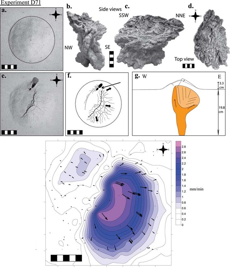
Figure 8. Illustration of (a) experiment D612 and (b) experiment D514. (a) D612 shows a typical dyke
with an asymmetric height profile. The dyke outbreaks close to the cone base. Dyke ascent is associated
with a minor extension above the dyke tip, focusing close to the outbreak location at the end of the
experiment. (b) D514 shows an asymmetric cup-shaped intrusion above a dyke developing away from the
cone summit. Intrusion is associated with summit fracturing and bulging.
of the gelatin block. Dyke orientation was controlled by ancy-driven dyke ascent, 2 ml of air was manually injected
cutting an initial fissure into the gelatin base with a syringe in other experiments and left to rise under buoyancy.
tip. As the density contrast between injected water and Volcano load is simulated using a cone made up of granular
gelatin is low, the intrusion is mostly driven by liquid material. Using a deformable load, rather than a metal bar as
overpressure rather than by buoyancy. To simulate buoy- done by Muller et al. [2001] or Watanabe et al. [2002],
16 of 26B03401 KERVYN ET AL.: VOLCANO LOAD CONTROL ON DYKE PROPAGATION B03401
Figure 9. Illustration of experiment D71 showing a dyke and sill complex intrusion associated with an
asymmetric graben. (a, e) Top views of initial and final model surfaces and (f) interpretation of the
deformation structures (arrow pointing to extrusion point); (b – c) side and (d) top views of the excavated
intrusion; (g) sketch of a cross section through the model showing the relationship between intrusion and
cone deformation; (h) deformation field during the time elapsed between 6 and 3 min prior to extrusion.
Colour scale and contours (0.2-mm/min interval) show horizontal displacement velocity with vectors
giving the orientation of surface displacements (derived using PointCatcher, software written by M. R.
James). Scales are 5 cm long.
17 of 26B03401 KERVYN ET AL.: VOLCANO LOAD CONTROL ON DYKE PROPAGATION B03401
Figure 10. Illustration of contrasted types of experiments: (a) D63: asymmetric dyke dividing into two
complementary oblique sheets close to the surface; (b) D75: asymmetric dyke with a minor dyke branch
perpendicular to the main one in the lower part. Outbreak occurs at BIS and is associated with minor
deformation due to low slope angle; (c) D520: dyke and sill complex below a broad, but low-slope-angle
cone, associated with minor deformation; outbreak is close to summit; (d) D417: chamber growth below a
narrow steep cone with outbreak of a thick oblique sheet and major flank deformation; (e) C3: near-
cylindrical conduit-shaped intrusion formed after the initiation of a narrow conduit up to cone base;
within the cone, the intrusion turns into a subhorizontal intrusion sheet.
enabled us to reproduce the 3D reorientation of stresses [41] The key observation in all experiments is the stalling
below a conical edifice. The higher density of the cone of the rising dyke when approaching the cone base. A
relative to the gelatin results in an enhanced effect of the marked decrease in upward propagation velocity occurred
load on the stress field in the gelatin. Dyke propagation was 5 –8 cm below the cone base (depth 1 – 1.5 cone radius,
visualized by taking photos from the side at regular time Figure 11). If water injection is stopped at this point, the
intervals (Figure 11). Ten experiments were carried out dyke does not reach the surface. When injection is contin-
under similar conditions and cone load. For three of them ued, the dyke continues rising vertically at very low velocity
air was injected instead of dyed water. and significantly enlarges horizontally. The dyke develops
two lateral lobes, one often being favored. The dyke
4.3. Experimental Results breaches the surface once one lobe reaches the cone base
[40] For dykes offset from the cone axis and initiated in a (Figure 11a). It is not the outermost part of the dyke that
direction perpendicular to that defined by the cone summit- breaches the surface. If the initial intrusion point is offset
injection point line, the dyke propagates toward the cone from the cone apex along the dyke propagation plane, the
symmetry axis as described in previous studies [Muller et dyke propagates asymmetrically toward the nearest point of
al., 2001; Watanabe et al., 2002]. When injected below the the cone base. Extrusion fissures initiate within a centimeter
cone apex, dykes rose vertically. from cone base. They are 2 cm long, with a radial or
subradial orientation relative to the cone summit.
18 of 26B03401 KERVYN ET AL.: VOLCANO LOAD CONTROL ON DYKE PROPAGATION B03401
Figure 11. Illustrations of observations from (a) dyed water and (b) air injections into a gelatin block
overlain by a sand and plaster cone. Lines show the outline of the intrusion at different time steps. Photos
illustrate the intrusion shape at specific time t. Evolution of the dyke outline for both types of experiments
illustrates that the dyke rise velocity decreases when approaching the cone base. The dyke propagates
laterally until extrusion is possible at the cone base. Air injection due to its lower density, forms a small
dyke which rises buoyantly and is able to approach closer to the cone base interface. Scales are 5 cm
long.
[42] Some dykes, which stalled below the cone base dyke ascent and promotes lateral intrusion propagation. For
without expanding laterally because of lack of additional most experiments simulating dyke ascent underneath a steep
fluid injection, were observed to rise and erupt directly after stratovolcano without opened conduit, extrusions occurred
the cone load was removed from the gelatin surface. This at the base or within the lower flanks, except for thin
illustrates that it was the volcano load that prevented dykes substratum. In the latter case, the dyke could not develop
from reaching the surface. It suggests that unloading pro- a sufficient length to reach cone base and the dyke devel-
cesses (i.e., flank collapse, caldera formation or erosion) can oped within the cone.
trigger eruption of magma stored in the central part of the [45] Gelatin models allow observation of the propagation
system, as proposed by Pinel and Jaupart [2000]. and evolution of planar dyke sheets with a simple geometry.
[43] When air is injected, the dyke starts stalling at 4 cm They do not render the complexity of intrusions observed in
from the cone base (depth 0.8 cone radius). This great nature. This is due to the fact that gelatin is too stiff and
decrease in dyke vertical velocity is associated with a drastic cannot break under shear, as rocks do. Sand-box models are
decrease in the dyke aspect ratio (dyke height/length), the more suitable analogues and result in complex intrusion mor-
dyke length being greater than its height close to the phologies, consistent with field observations [e.g., Emeleus
extrusion point (Figure 11b). Air dykes reached within a and Bell, 2005; Mathieu et al., 2008]. Intrusions with multi-
few millimeters of the cone-gelatin interface but were not ple branches associated with important changes in propa-
able to break through the gelatin surface. Air dykes prop- gation direction, sills or oblique intrusions were observed
agate laterally at a low rate until being able to breach the to form.
surface at the cone base. The fact that air dykes can [46] Analogue experiments allow identification of the
approach closer to the cone-gelatin interface than water main controlling parameters on the dyke propagation sys-
dykes before being affected by the cone load suggests that tem beneath a volcano. For sand-box experiments, cone
stalling and lateral propagation effects depend on the aspect ratio (P1), cone height and relative crustal thickness
balance between dyke buoyancy and edifice-induced stress. (P2) are the fundamental parameters controlling the offset
of the extrusion outbreak (P5). Although the effect of each
5. Discussion parameter was not constrained for the gelatin models, it is
expected that the lateral deviation of the intrusion will
5.1. Volcano Load Effect on Dyke Propagation
increase with cone height or cone slope and decrease with
[44] Both types of experiments provide insights into the increasing dyke overpressure or density contrast.
effect of edifice load upon dyke propagation and extrusion [47] The increasing load can ultimately prevent vertical
point location. In both cases, cone load inhibits vertical magma ascent in the edifice axial zone, the threshold
19 of 26B03401 KERVYN ET AL.: VOLCANO LOAD CONTROL ON DYKE PROPAGATION B03401
depending on the magma density and overpressure [Carr, secting the surface at the cone base when initiated at great
1984; van Wyk de Vries and Borgia, 1996; Pinel and depth is also an important constraint for eruption outbreak
Jaupart, 2000]. If a dyke cannot erupt through the volcano location, as suggested by numerical modeling by Gaffney
axial zone, magma either is intruded beneath the edifice and and Damjanac [2006].
stored in the axial zone, as observed in our gelatin models [51] A decrease in dyke ascent velocity was observed in
with limited intrusion volume, or propagates laterally to gelatin models as the dyke tip approached within 0.8 –1.5
feed a distal flank eruption [Pinel and Jaupart, 2004a, cone radius below the cone. This is consistent with numer-
Figure 12a]. A key control upon dyke ascent or storage is ical predictions of a marked propagation rate drop due to the
the relative magnitude of the dyke driving pressure and compressive stress generated by edifice load [Pinel and
edifice-induced stress. Jaupart, 2000; Watanabe et al., 2002] when magma reaches
[48] To compare our experimental results with numerical a depth equal to the volcano radius. This decrease in vertical
predictions of Pinel and Jaupart [2000, 2004b], GS intru- ascent velocity could not be directly observed in the sand-
sions were classified on the basis of the evidence for box experiments, but can be extrapolated from observations
intrusion stalling and/or lateral propagation. Intrusion stall- of a corresponding level of greater horizontal extension for
ing was characterized by a reservoir-like feature or a level of the intrusions.
greater horizontal propagation, whereas lateral propagation
was marked by significant horizontal deviation of the 5.2. Limitations of Experiments and Additional Key
extrusion point (P5 > 0.4, Table 3 and Figure 12). A main Factors
difference between the experiments and the Pinel and [52] Analogue experiments enable visualization and anal-
Jaupart [2000, 2004b] predictions is that GS, after stalling, ysis of a simplified representation of a natural system. In
always reached the surface because of maintained overpres- addition to the inherent randomness of experimental results,
sure, whereas in numerical models, magma which had several limitations of the analogue models can be highlight-
insufficient pressure to propagate laterally was stored below ed. First, some components of natural volcanic systems are
the volcano. not accounted for in our analogue experiments. Experiments
[49] Figures 12b– 12c show that it is only for dykes with with a pre-established conduit up to the cone base showed
limited relative overpressure (low P11 value) rising under that an established magmatic system (i.e., magma chamber,
steep cones that edifice-induced load is dominant and forces conduits, former intrusions) existing below and within
the intrusion to propagate laterally. For a higher relative over- volcanoes reduces the cone load control upon magma
pressure, magma tends to form reservoir-like features that propagation. In the natural cases, this factor can account
enable the intrusion to build up sufficient pressure to still for the occurrence of most eruptions in the axial zones of
propagate in the central part of the edifice, if cone slope is natural volcanoes. A central conduit, or a central weak zone,
not too high. For low-angle cones, dykes can erupt through through which successive intrusions preferentially propa-
the central part of the edifice without a storage phase. These gate, generally characterizes volcanoes with regular erup-
observations are consistent with relationships proposed by tions, i.e., volcanoes where dyke ascent timescale is smaller
Pinel and Jaupart [2004b, Figure 12a], except that magma or equal to dyke cooling or closure timescales, which
stalling at shallow level was the typical behavior of low themselves depend on dyke width and driving overpressure,
dyke overpressure (higher magma density) in their numer- in turn dependent on the magma rheology and supply rate.
ical model. Lateral propagation occurred for dykes with high [53] Second, volcano load and regular magma intrusion
overpressure (less dense magma) because intrusions were can favor the formation of shallow magma chambers in
driven by buoyancy and could not develop into reservoirs which magma can evolve [van Wyk de Vries and Borgia,
where magma can accumulate and pressure can build up. 1996; Pinel and Jaupart, 2000; Muller et al., 2001; Borgia
[50] Figures 12c– 12d show that lateral dyke propagation and van Wyk de Vries, 2003]. Analogue experiments pre-
is also constrained by the relative depth of dyke initiation sented here are only valid for vertical dykes rising from
(P2). Evidence of lateral propagation is observed for low depth (i.e., a deep reservoir) in the volcano axial zone
values of P2, and thus deep initiation relative to cone size. If without intersecting any pre-existing shallow chambers.
the source is shallow (high P2 value), the dyke will stall and This is the case for volcanoes with a long repose time, or
finally extrude within the upper cone, if magma input is for magmas rising at the system periphery [e.g., Etna 2000,
sufficient. This can be related to the general increase in dyke Acocella and Neri, 2003], bypassing shallow chambers.
length for thicker crust. It suggests that in addition to the Numerical models by Pinel and Jaupart [2003] for dyke
volcano load effect, the geometric effect of a dyke inter- nucleation from a pressurized magma chamber under a
Figure 12. Relationships between experimental dimensionless numbers and the type of interaction between cone load and
ascending intrusions. (a) Graphical sketch of the relationships obtained from the numerical modeling of dykes ascending
from a deep source underneath a cone with a fixed slope [after Pinel and Jaupart, 2004b]; (b) dyke behavior in sand-box
experiments for varying cone slope (P1) and relative intrusion overpressure (P11); (c) schematic summary of dyke behavior
in function of P1 and P11; (d) dyke behavior in sand-box experiments for varying cone slope (P1) versus cone size relative
to crust thickness (P2); (e) schematic summary of dyke behavior in function of P1 and P2. Note that Figures 12c and 12e
are merely illustrating the likely, or dominant, behavior of dyke propagation for contrasting experimental conditions.
Significant overlap is observed between these fields in the experimental results. This overlap is attributed to the inherent
variability in the experiments.
20 of 26You can also read