Automated Thermal Cycler (ATC) System - USER GUIDE - Thermo Fisher ...
←
→
Page content transcription
If your browser does not render page correctly, please read the page content below

Automated Thermal Cycler (ATC) System
USER GUIDE

Installation, use, and maintenance

Catalog Numbers A30207, A30208, A31486, A31487, A31488, A31489, A31490, A31491, A33976,
A33977, A33978, A33979, A33980, A33981, and A33982
Publication Number MAN0014558
Revision B.0

For Research Use Only. Not for use in diagnostic procedures.

Life Technologies Holdings Pte Ltd | Block 33 | Marsiling Industrial Estate Road 3 | #07-06, Singapore 739256
       For descriptions of symbols on product labels or product documents, go to thermofisher.com/symbols-definition.

The information in this guide is subject to change without notice.
DISCLAIMER: TO THE EXTENT ALLOWED BY LAW, THERMO FISHER SCIENTIFIC INC. AND/OR ITS AFFILIATE(S) WILL NOT BE
LIABLE FOR SPECIAL, INCIDENTAL, INDIRECT, PUNITIVE, MULTIPLE, OR CONSEQUENTIAL DAMAGES IN CONNECTION WITH OR
ARISING FROM THIS DOCUMENT, INCLUDING YOUR USE OF IT.

Revision history: Pub. No. MAN0014558
         Revision                       Date                                                 Description
            B.0                    17 June 2021         Addition of the Fleet software appendix, and a sentence in the product description
                                                        regarding the Fleet software.
            A.0                    11 April 2017        New document. Describes installation, operation, and maintenance of the Automated
                                                        Thermal Cycler (ATC) System.

Important Licensing Information: This product may be covered by one or more Limited Use Label Licenses. By use of this product,
you accept the terms and conditions of all applicable Limited Use Label Licenses.
TRADEMARKS: All trademarks are the property of Thermo Fisher Scientific and its subsidiaries unless otherwise specified.
©2021 Thermo Fisher Scientific Inc. All rights reserved.
Contents

  ■    CHAPTER 1 About the Automated Thermal Cycler (ATC) System . . . . . . . . . . . . . 6

                        Package contents . . . . . . . . . . . . . . . . . . . . . . . . . . . . . . . . . . . . . . . . . . . . . . . . . . . . . . . . . . . . . . . 6
                        Setup options . . . . . . . . . . . . . . . . . . . . . . . . . . . . . . . . . . . . . . . . . . . . . . . . . . . . . . . . . . . . . . . . . . 7
                        Site requirements . . . . . . . . . . . . . . . . . . . . . . . . . . . . . . . . . . . . . . . . . . . . . . . . . . . . . . . . . . . . . . . 7
                        Environmental requirements . . . . . . . . . . . . . . . . . . . . . . . . . . . . . . . . . . . . . . . . . . . . . . . . . . . . . . 8
                             Temperature and humidity requirements . . . . . . . . . . . . . . . . . . . . . . . . . . . . . . . . . . . . . . . 8
                             Pollution . . . . . . . . . . . . . . . . . . . . . . . . . . . . . . . . . . . . . . . . . . . . . . . . . . . . . . . . . . . . . . . . . . . 8
                        Technical specifications . . . . . . . . . . . . . . . . . . . . . . . . . . . . . . . . . . . . . . . . . . . . . . . . . . . . . . . . . . 8
                        System specifications . . . . . . . . . . . . . . . . . . . . . . . . . . . . . . . . . . . . . . . . . . . . . . . . . . . . . . . . . . . 9
                        Location of power points and ports . . . . . . . . . . . . . . . . . . . . . . . . . . . . . . . . . . . . . . . . . . . . . . 10
                        Use ATC plate adaptors . . . . . . . . . . . . . . . . . . . . . . . . . . . . . . . . . . . . . . . . . . . . . . . . . . . . . . . . . 11

  ■    CHAPTER 2 Operate the Automated Thermal Cycler (ATC) System as
        a stand-alone system . . . . . . . . . . . . . . . . . . . . . . . . . . . . . . . . . . . . . . . . . . . . . . . . . . . . . . . . . . . . . 15

                        Connect the hardware . . . . . . . . . . . . . . . . . . . . . . . . . . . . . . . . . . . . . . . . . . . . . . . . . . . . . . . . . . 15
                        Operate ATC as stand alone using computer . . . . . . . . . . . . . . . . . . . . . . . . . . . . . . . . . . . . . . 15
                        Program and execute a run on the ATC . . . . . . . . . . . . . . . . . . . . . . . . . . . . . . . . . . . . . . . . . . . 18
                        Connect to multiple instruments using the desktop software . . . . . . . . . . . . . . . . . . . . . . . . . 22
                        Firmware upgrades . . . . . . . . . . . . . . . . . . . . . . . . . . . . . . . . . . . . . . . . . . . . . . . . . . . . . . . . . . . . . 23

  ■    CHAPTER 3 Operate the Automated Thermal Cycler (ATC) System as
        part of a robotic system . . . . . . . . . . . . . . . . . . . . . . . . . . . . . . . . . . . . . . . . . . . . . . . . . . . . . . . . . . 26

                        Set up the Automated Thermal Cycler (ATC) System on a robotic system . . . . . . . . . . . . . 26
                             Guidelines for robotic configurations . . . . . . . . . . . . . . . . . . . . . . . . . . . . . . . . . . . . . . . . . 28
                        Connect Automated Thermal Cycler to a robotic system . . . . . . . . . . . . . . . . . . . . . . . . . . . . 28
                        Perform a thermal protocol run . . . . . . . . . . . . . . . . . . . . . . . . . . . . . . . . . . . . . . . . . . . . . . . . . .               28
                             (Optional) View the progress of the thermal protocol run . . . . . . . . . . . . . . . . . . . . . . . .                                    30
                             (Optional) Abort the thermal protocol run . . . . . . . . . . . . . . . . . . . . . . . . . . . . . . . . . . . . .                         31
                             (Optional) Control the automated heated cover lid . . . . . . . . . . . . . . . . . . . . . . . . . . . . . .                               31

Automated Thermal Cycler (ATC) System User Guide                                                                                                                           3
Contents

    ■   CHAPTER 4 Maintain the Automated Thermal Cycler (ATC) System . . . . . . . . . 32

                       Clean the instrument . . . . . . . . . . . . . . . . . . . . . . . . . . . . . . . . . . . . . . . . . . . . . . . . . . . . . . . . . . .            32
                           Preparation . . . . . . . . . . . . . . . . . . . . . . . . . . . . . . . . . . . . . . . . . . . . . . . . . . . . . . . . . . . . . . .         32
                           Clean the sample wells . . . . . . . . . . . . . . . . . . . . . . . . . . . . . . . . . . . . . . . . . . . . . . . . . . . . .                  32
                           Decontaminate the sample wells . . . . . . . . . . . . . . . . . . . . . . . . . . . . . . . . . . . . . . . . . . . . .                          33
                           Clean the heated cover . . . . . . . . . . . . . . . . . . . . . . . . . . . . . . . . . . . . . . . . . . . . . . . . . . . . .                  34
                           Decontaminate the heated cover . . . . . . . . . . . . . . . . . . . . . . . . . . . . . . . . . . . . . . . . . . . .                            34
                       Replace the fuses . . . . . . . . . . . . . . . . . . . . . . . . . . . . . . . . . . . . . . . . . . . . . . . . . . . . . . . . . . . . . . 34
                       Separate the heated cover from the block . . . . . . . . . . . . . . . . . . . . . . . . . . . . . . . . . . . . . . . . . 35

    ■   APPENDIX A Parts and materials . . . . . . . . . . . . . . . . . . . . . . . . . . . . . . . . . . . . . . . . . . . . . . . . 40

                       Accessories . . . . . . . . . . . . . . . . . . . . . . . . . . . . . . . . . . . . . . . . . . . . . . . . . . . . . . . . . . . . . . . . . . . 40

    ■   APPENDIX B Command dictionaries . . . . . . . . . . . . . . . . . . . . . . . . . . . . . . . . . . . . . . . . . . . . 41

                       Command directory overview . . . . . . . . . . . . . . . . . . . . . . . . . . . . . . . . . . . . . . . . . . . . . . . . . . . . 41
                       Mandatory commands . . . . . . . . . . . . . . . . . . . . . . . . . . . . . . . . . . . . . . . . . . . . . . . . . . . . . . . . . .                42
                          Abort . . . . . . . . . . . . . . . . . . . . . . . . . . . . . . . . . . . . . . . . . . . . . . . . . . . . . . . . . . . . . . . . . . . . .    42
                          DoContinue . . . . . . . . . . . . . . . . . . . . . . . . . . . . . . . . . . . . . . . . . . . . . . . . . . . . . . . . . . . . . . .           42
                          GetDeviceIdentification . . . . . . . . . . . . . . . . . . . . . . . . . . . . . . . . . . . . . . . . . . . . . . . . . . . . .                  43
                          GetStatus . . . . . . . . . . . . . . . . . . . . . . . . . . . . . . . . . . . . . . . . . . . . . . . . . . . . . . . . . . . . . . . . .        44
                          Initialize . . . . . . . . . . . . . . . . . . . . . . . . . . . . . . . . . . . . . . . . . . . . . . . . . . . . . . . . . . . . . . . . . .     44
                          LockDevice . . . . . . . . . . . . . . . . . . . . . . . . . . . . . . . . . . . . . . . . . . . . . . . . . . . . . . . . . . . . . . .           44
                          Pause . . . . . . . . . . . . . . . . . . . . . . . . . . . . . . . . . . . . . . . . . . . . . . . . . . . . . . . . . . . . . . . . . . . .      45
                          Reset . . . . . . . . . . . . . . . . . . . . . . . . . . . . . . . . . . . . . . . . . . . . . . . . . . . . . . . . . . . . . . . . . . . .      45
                          UnlockDevice . . . . . . . . . . . . . . . . . . . . . . . . . . . . . . . . . . . . . . . . . . . . . . . . . . . . . . . . . . . . .             46
                       Required Commands for PCR Cyclers . . . . . . . . . . . . . . . . . . . . . . . . . . . . . . . . . . . . . . . . . . . .                             46
                           Delay . . . . . . . . . . . . . . . . . . . . . . . . . . . . . . . . . . . . . . . . . . . . . . . . . . . . . . . . . . . . . . . . . . . . .   46
                           GetParameters . . . . . . . . . . . . . . . . . . . . . . . . . . . . . . . . . . . . . . . . . . . . . . . . . . . . . . . . . . . .             47
                           PrepareForInput . . . . . . . . . . . . . . . . . . . . . . . . . . . . . . . . . . . . . . . . . . . . . . . . . . . . . . . . . . .             47
                           PrepareForOutput . . . . . . . . . . . . . . . . . . . . . . . . . . . . . . . . . . . . . . . . . . . . . . . . . . . . . . . . . .              48
                           SetParameters . . . . . . . . . . . . . . . . . . . . . . . . . . . . . . . . . . . . . . . . . . . . . . . . . . . . . . . . . . . .             48
                       Optional commands for PCR Cyclers . . . . . . . . . . . . . . . . . . . . . . . . . . . . . . . . . . . . . . . . . . . . . 49
                           GetConfiguration . . . . . . . . . . . . . . . . . . . . . . . . . . . . . . . . . . . . . . . . . . . . . . . . . . . . . . . . . . 49
                           SetConfiguration . . . . . . . . . . . . . . . . . . . . . . . . . . . . . . . . . . . . . . . . . . . . . . . . . . . . . . . . . . 50
                       Optional commands for other device classes . . . . . . . . . . . . . . . . . . . . . . . . . . . . . . . . . . . . . . 51
                           OpenDoor . . . . . . . . . . . . . . . . . . . . . . . . . . . . . . . . . . . . . . . . . . . . . . . . . . . . . . . . . . . . . . . . 51
                           CloseDoor . . . . . . . . . . . . . . . . . . . . . . . . . . . . . . . . . . . . . . . . . . . . . . . . . . . . . . . . . . . . . . . . 51
                       Specific commands . . . . . . . . . . . . . . . . . . . . . . . . . . . . . . . . . . . . . . . . . . . . . . . . . . . . . . . . . . . .             52
                           ExecuteProtocol . . . . . . . . . . . . . . . . . . . . . . . . . . . . . . . . . . . . . . . . . . . . . . . . . . . . . . . . . . .             52
                           GetDeviceDetails . . . . . . . . . . . . . . . . . . . . . . . . . . . . . . . . . . . . . . . . . . . . . . . . . . . . . . . . . .              52
                           GetProtocolDefinition . . . . . . . . . . . . . . . . . . . . . . . . . . . . . . . . . . . . . . . . . . . . . . . . . . . . . .                 53
                           GetProtocolDetails . . . . . . . . . . . . . . . . . . . . . . . . . . . . . . . . . . . . . . . . . . . . . . . . . . . . . . . . .              54

4                                                                                                  Automated Thermal Cycler (ATC) System User Guide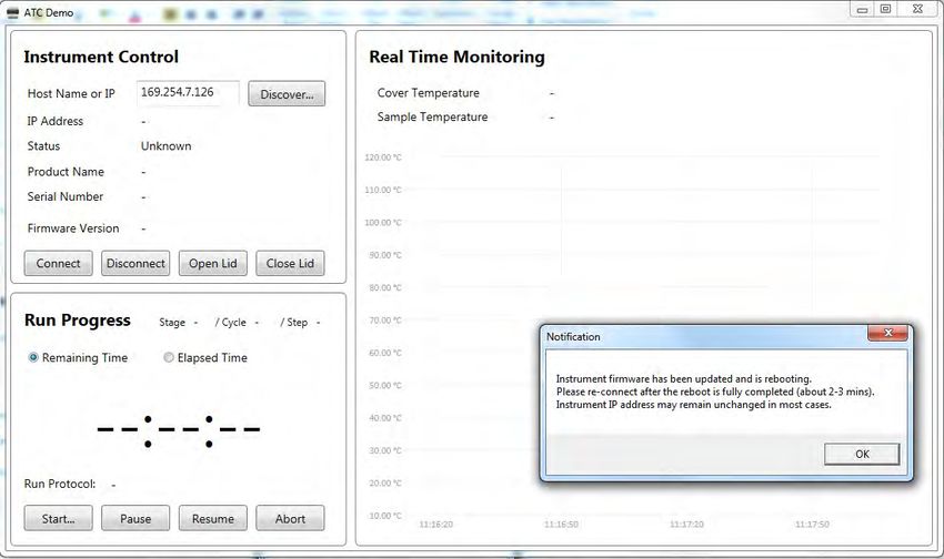
Contents

                                StopProtocol . . . . . . . . . . . . . . . . . . . . . . . . . . . . . . . . . . . . . . . . . . . . . . . . . . . . . . . . . . . . . . 55
                                SubScribe . . . . . . . . . . . . . . . . . . . . . . . . . . . . . . . . . . . . . . . . . . . . . . . . . . . . . . . . . . . . . . . . 55
                                UnSubScribe . . . . . . . . . . . . . . . . . . . . . . . . . . . . . . . . . . . . . . . . . . . . . . . . . . . . . . . . . . . . . . 55
                        SiLA return codes . . . . . . . . . . . . . . . . . . . . . . . . . . . . . . . . . . . . . . . . . . . . . . . . . . . . . . . . . . . . . . 56

  ■    APPENDIX C About the Thermal Cycler Fleet Control Software . . . . . . . . . . . . . . 57

                        Connect the thermal cycler to the network . . . . . . . . . . . . . . . . . . . . . . . . . . . . . . . . . . . . . . . . 57

  ■    APPENDIX D Safety . . . . . . . . . . . . . . . . . . . . . . . . . . . . . . . . . . . . . . . . . . . . . . . . . . . . . . . . . . . . . . . 58

                        Symbols on this instrument . . . . . . . . . . . . . . . . . . . . . . . . . . . . . . . . . . . . . . . . . . . . . . . . . . . . . 58
                           Conformity symbols . . . . . . . . . . . . . . . . . . . . . . . . . . . . . . . . . . . . . . . . . . . . . . . . . . . . . . . . 60
                        Safety alerts on this instrument . . . . . . . . . . . . . . . . . . . . . . . . . . . . . . . . . . . . . . . . . . . . . . . . . . 60
                            Location of safety labels on the instrument . . . . . . . . . . . . . . . . . . . . . . . . . . . . . . . . . . . . 60
                        Safety information for instruments not manufactured by Thermo Fisher Scientific . . . . . . 62
                        Instrument safety . . . . . . . . . . . . . . . . . . . . . . . . . . . . . . . . . . . . . . . . . . . . . . . . . . . . . . . . . . . . . .        62
                             General . . . . . . . . . . . . . . . . . . . . . . . . . . . . . . . . . . . . . . . . . . . . . . . . . . . . . . . . . . . . . . . . . . .   62
                             Physical injury . . . . . . . . . . . . . . . . . . . . . . . . . . . . . . . . . . . . . . . . . . . . . . . . . . . . . . . . . . . . .       62
                             Electrical safety . . . . . . . . . . . . . . . . . . . . . . . . . . . . . . . . . . . . . . . . . . . . . . . . . . . . . . . . . . .         63
                             Cleaning and decontamination . . . . . . . . . . . . . . . . . . . . . . . . . . . . . . . . . . . . . . . . . . . . . .                        63
                             Instrument component and accessory disposal . . . . . . . . . . . . . . . . . . . . . . . . . . . . . . . .                                     63
                        Safety and electromagnetic compatibility (EMC) standards . . . . . . . . . . . . . . . . . . . . . . . . . .                                         63
                            Safety . . . . . . . . . . . . . . . . . . . . . . . . . . . . . . . . . . . . . . . . . . . . . . . . . . . . . . . . . . . . . . . . . . . .   64
                            EMC . . . . . . . . . . . . . . . . . . . . . . . . . . . . . . . . . . . . . . . . . . . . . . . . . . . . . . . . . . . . . . . . . . . . .    64
                            Environmental design . . . . . . . . . . . . . . . . . . . . . . . . . . . . . . . . . . . . . . . . . . . . . . . . . . . . . .                 65
                            RoHS . . . . . . . . . . . . . . . . . . . . . . . . . . . . . . . . . . . . . . . . . . . . . . . . . . . . . . . . . . . . . . . . . . . .     65
                        Chemical safety . . . . . . . . . . . . . . . . . . . . . . . . . . . . . . . . . . . . . . . . . . . . . . . . . . . . . . . . . . . . . . . . 66
                        Biological hazard safety . . . . . . . . . . . . . . . . . . . . . . . . . . . . . . . . . . . . . . . . . . . . . . . . . . . . . . . . . 67

  ■    APPENDIX E Documentation and support . . . . . . . . . . . . . . . . . . . . . . . . . . . . . . . . . . . . . . 68

                        Related documentation . . . . . . . . . . . . . . . . . . . . . . . . . . . . . . . . . . . . . . . . . . . . . . . . . . . . . . . . . 68
                        Customer and technical support . . . . . . . . . . . . . . . . . . . . . . . . . . . . . . . . . . . . . . . . . . . . . . . . . 68
                        Limited product warranty . . . . . . . . . . . . . . . . . . . . . . . . . . . . . . . . . . . . . . . . . . . . . . . . . . . . . . . . 69

Automated Thermal Cycler (ATC) System User Guide                                                                                                                             5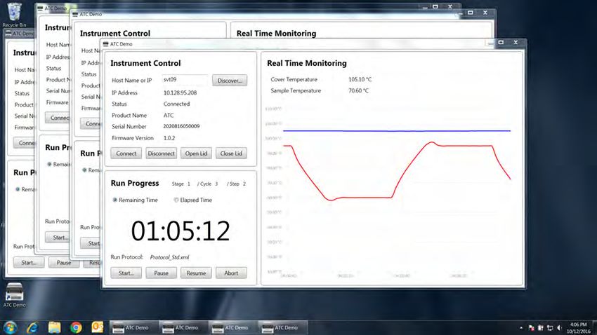
1                                             About the Automated Thermal
                                                           Cycler (ATC) System

    ■     Package contents . . . . . . . . . . . . . . . . . . . . . . . . . . . . . . . . . . . . . . . . . . . . . . . . . . . . . . . . . . . . . . . . . . . . . 6
    ■     Setup options . . . . . . . . . . . . . . . . . . . . . . . . . . . . . . . . . . . . . . . . . . . . . . . . . . . . . . . . . . . . . . . . . . . . . . . . . 7
    ■     Site requirements . . . . . . . . . . . . . . . . . . . . . . . . . . . . . . . . . . . . . . . . . . . . . . . . . . . . . . . . . . . . . . . . . . . . . 7
    ■     Environmental requirements . . . . . . . . . . . . . . . . . . . . . . . . . . . . . . . . . . . . . . . . . . . . . . . . . . . . . . . . . . . . 8
    ■     Technical specifications . . . . . . . . . . . . . . . . . . . . . . . . . . . . . . . . . . . . . . . . . . . . . . . . . . . . . . . . . . . . . . . . 8
    ■     System specifications . . . . . . . . . . . . . . . . . . . . . . . . . . . . . . . . . . . . . . . . . . . . . . . . . . . . . . . . . . . . . . . . . . 9
    ■     Location of power points and ports . . . . . . . . . . . . . . . . . . . . . . . . . . . . . . . . . . . . . . . . . . . . . . . . . . . . . 10
    ■     Use ATC plate adaptors . . . . . . . . . . . . . . . . . . . . . . . . . . . . . . . . . . . . . . . . . . . . . . . . . . . . . . . . . . . . . . . 11

    The Automated Thermal Cycler (ATC) System is designed for integrating with laboratory automation
    products of other equipment manufacturers (OEM) for use in automation workflows. The Automated
    Thermal Cycler (ATC) System can also be used as a stand-alone device in conjunction with a third-party
    desktop software. It is also compatible with the Applied Biosystems™ Thermal Cycler Fleet Control
    Software.
    The Automated Thermal Cycler (ATC) System supports 96-Well, 384-Well, and 0.2-mL sample block
    configuration and includes three components:
        • A thermal block and heated cover that constitute the thermal cycler unit
        • A power box

    A power cable is used for connecting the thermal cycler to the power box.
    For details on Automated Thermal Cycler (ATC) System specifications and layout, see “System
    specifications” on page 9.

Package contents
    The Automated Thermal Cycler (ATC) System comes in two boxes.
    The ATC Block Module box contains:
        • ATC 96-Well Block module and/or 384-Well Block module
        • CAT5 Ethernet cable
        • Power cord
        • Certificate of analysis
        • Product documentation

6                                                                                                 Automated Thermal Cycler (ATC) System User Guide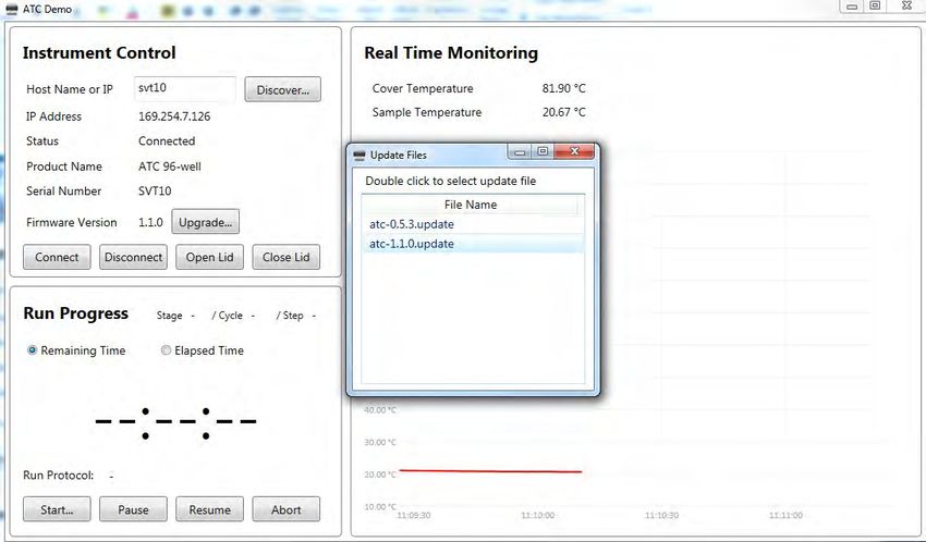
Chapter 1 About the Automated Thermal Cycler (ATC) System
                                                                                                                     Setup options   1

       The ATC Control Module box contains:
         • ATC Control Module

Setup options
       The system can be set up in two ways.

       Table 2 Automated Thermal Cycler (ATC) System configurations

                Setup option                                             image

        Within a Robotic environment                                                      Automated Thermal
                                                                                                            Cycler

        Stand-alone system                                             Automated Thermal Cycler

Site requirements
       The Automated Thermal Cycler (ATC) System is for indoor use. Ensure that the installation site:
         • Meets the spatial and weight requirements (see “System specifications” on page 9)
         • Meets environmental requirements (see “Environmental requirements” on page 8)
         • Is within 1 m (3 ft.) of an AC power source receptacle
         • Is away from water

Automated Thermal Cycler (ATC) System User Guide                                                                                     7
Chapter 1 About the Automated Thermal Cycler (ATC) System
 1    Environmental requirements

Environmental requirements
Temperature and humidity requirements
          Ensure that the installation site is maintained under the following conditions:

Table 3 Temperature and humidity requirements

                          Condition                                             Acceptable range

Temperature                                                                   15 to 30°C (59 to 86°F)

Humidity                                                           15 to 80% relative humidity, non-condensing

          Avoid placing the instrument adjacent to heaters, cooling ducts, or in direct sunlight. Fluctuations
          between day and night temperatures can cause system instability. Place away from any equipment that
          vibrates, such as a refrigerator or centrifuge.

Pollution
          The Automated Thermal Cycler (ATC) System has a Pollution Degree rating of 2. It may be installed in
          an environment that has non-conductive pollutants only, such as dust particles or wood chips. Typical
          environments with a Pollution Degree II rating are laboratories and sales and commercial areas.

Technical specifications
Table 4     Automated Thermal Cycler (ATC) System technical specifications:

                Feature                                                 Specification

Block format                            •                                96-well, 0.2-mL
                                        •                               384-well, 0.02-mL

Maximum block ramp rate[1]              •                              3.5°C/sec (96-well)
                                        •                              2.8°C/sec (384-well)

Maximum sample ramp rate[1]             •                              1.8°C/sec (96-well)
                                        •                              1.6°C/sec (384-well)

Temperature range for                                                 0.0°C to 105.0°C
protocol run

Temperature uniformity                                      ≤0.50°C (20 sec after reaching 95°C)

Temperature calibration                  Calibrated to standards traceable to the National Institute of Standards and
                                                                     Technology (NIST™)

Dimensions                                         Thermal Module                             Control Module

8                                                                     Automated Thermal Cycler (ATC) System User Guide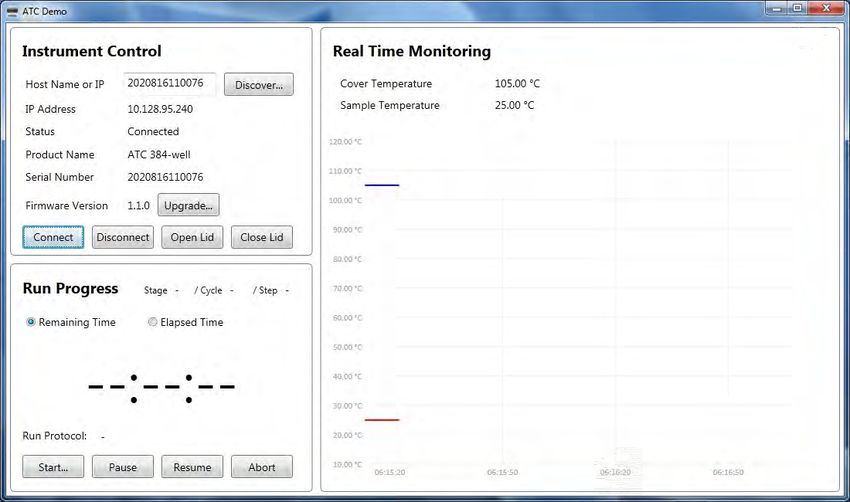
Chapter 1 About the Automated Thermal Cycler (ATC) System
                                                                                                  System specifications   1

Table 4       Automated Thermal Cycler (ATC) System technical specifications: (continued)

                   Feature                                                Specification

 Dimensions                            •         Height: 133.6 mm (5.3 in)           •     Height: 76.4 mm (3.0 in) —
                                       •          Width: 179.6 mm (7.1 in)                   (including rubber feet)
                                       •         Depth: 317.5 mm (12.5 in)           •       Width: 257 mm (10.1 in)
                                                                                     •     Depth: 342.0 mm (13.5 in) —
                                                                                               (including air vents)

 Weight                                •                     Weight of Thermal Module: 6.0 kg (13.2 lb)
                                       •                     Weight of Control Module: 3.4 kg (7.48 lb)
                                       •                   Weight of 1m Interface Cable: 0.35 kg (0.77 lb)

 PCR volume range                      •                                  10−100 µL (96-well)
                                       •                                  5−10 µL (384-well)

 Instrument memory                                                             USB

 Power                                                         100-240 V, 50-60 Hz Max: 600 W
[1]   Reaction volume @ 1 µL

System specifications
Table 5 Physical dimensions and weight, and power consumption

                                                   Instrument footprint                   Recommended clearance
                  Dimension
                                           Thermal module        Control box         Thermal module         Control box

 Height                                    133.6 mm (5.3 in) 76.4 mm (3.0 in)      N/A                   N/A

 Width                                     179.6 mm (7.1 in) 257.0 mm              N/A                   N/A
                                                             (10.1 in)

 Depth                                        317.5 mm        342.0 mm             Front: 51 mm          Front: 10 mm
                                               (12.5 in)      (13.5 in)            (2 in)                (0.39 in)
                                                                                   Rear: 102 mm          Rear: 10 mm
                                                                                   (4 in)                (0.39 in)

Automated Thermal Cycler (ATC) System User Guide                                                                          9
Chapter 1 About the Automated Thermal Cycler (ATC) System
1    Location of power points and ports

Location of power points and ports
                                                3                4                 5

      2

      1

     Figure 1 Back panel of the ATC control module
          1 Power port
          2 Power button
          3 Ethernet port
          4 Automated Thermal Cycler (ATC) System DSUB
          5 USB port

                                            1

     Figure 2 Back panel of the ATC block module
          1 Automated Thermal Cycler (ATC) System DSUB

10                                                                   Automated Thermal Cycler (ATC) System User Guide
Chapter 1 About the Automated Thermal Cycler (ATC) System
Use ATC plate adaptors 1
Use ATC plate adaptors
The plate adaptor helps to ensure that the supported consumables (full skirt and semi-skirt plates)
are ejected properly, and that the temperature is kept uniform. The Automated Thermal Cycler comes
factory configured with a full-skirted adaptor (amber color) already installed.
Note: ATC plate adaptors are only installed/required on the 96-well block. Adaptors are not required for
the 384-well block.
Figure 3 Automated Thermal Cycler 96-well block with full-skirted plate adaptor installed
• To uninstall the full-skirted adaptor, follow the instructions in Figure 4.
Automated Thermal Cycler (ATC) System User Guide 11Chapter 1 About the Automated Thermal Cycler (ATC) System
1 Use ATC plate adaptors
1 2 3
Figure 4 Uninstall the full-skirted plate adaptor
1 Slightly push the tabs highlighted in red.
2 Grab the bottom of the adaptor, and tilt up.
3 Remove the adaptor.
• To install full-skirted plate adaptor follow the instructions in Figure 5.
12 Automated Thermal Cycler (ATC) System User GuideChapter 1 About the Automated Thermal Cycler (ATC) System
Use ATC plate adaptors 1
1 2
3 4
Figure 5 Install full-skirted plate adaptor
1 Remove half skirted adaptor, if any. place full skirted adaptor by tilting an angle allowing the front to insert under
the frame.
2 Push the two tabs allowing it to be inserted into the frame.
3 Ensure the full-skirted plate adaptor sits freely under the frame.
4 Full-skirted plate adaptor is installed.
• To install the semi-skirted plate adaptor, follow the instructions in Figure 6.
Automated Thermal Cycler (ATC) System User Guide 13Chapter 1 About the Automated Thermal Cycler (ATC) System
1 Use ATC plate adaptors
1 2
3 4
Figure 6 Installation of semi-skirted plate adaptors and ejector buttons
1 Slot the semi-skirted plate adaptor to the gap between the Alu top plate and drip pan.
2 Slot in the adaptor and center it.
3 Snap fit the ejector buttons.
4 There are four ejector buttons.
14 Automated Thermal Cycler (ATC) System User Guide2 Operate the Automated Thermal
Cycler (ATC) System as a stand-
alone system
■ Connect the hardware . . . . . . . . . . . . . . . . . . . . . . . . . . . . . . . . . . . . . . . . . . . . . . . . . . . . . . . . . . . . . . . . 15
■ Operate ATC as stand alone using computer . . . . . . . . . . . . . . . . . . . . . . . . . . . . . . . . . . . . . . . . . . . . . 15
■ Program and execute a run on the ATC . . . . . . . . . . . . . . . . . . . . . . . . . . . . . . . . . . . . . . . . . . . . . . . . . . 18
■ Connect to multiple instruments using the desktop software . . . . . . . . . . . . . . . . . . . . . . . . . . . . . . . 22
■ Firmware upgrades . . . . . . . . . . . . . . . . . . . . . . . . . . . . . . . . . . . . . . . . . . . . . . . . . . . . . . . . . . . . . . . . . . . 23
This chapter describes the procedures for setting up and running the Automated Thermal Cycler (ATC)
System as a stand-alone system.
Connect the hardware
1. Connect the connector cable into the insertion points on the ATC block (Figure 1, item 4) and base
module (Figure 2, item 1)
Note: Ensure the DSUB connector is securely fastened.
2. Connect the power cable into the back of the ATC control module (Figure 1, item 1)
3. Connect the ethernet cable into the control module (Figure 1, item 3) and into the
computer/network that you will be using to control the ATC.
4. Power on the ATC.
Operate ATC as stand alone using computer
Make sure all hardware connections are completed.
1. Download the ATC desktop software at thermofisher.com and follow the installation instructions
found in the software release notes.
Note: To fully install the software, the computer will need to be connected to the internet. Once
the software is fully installed, disconnect the computer from the internet for best performance with
the ATC desktop software.
Automated Thermal Cycler (ATC) System User Guide 15Chapter 2 Operate the Automated Thermal Cycler (ATC) System as a stand-alone system
2 Operate ATC as stand alone using computer
2. Once the software is installed, click on the ATC Demo icon to launch the software.
Figure 7 Desktop icon of ATC Demo software
1 2
3
4
Figure 8 ATC Demo software initial screen
1 Discover
2 A pop up window
3 Identified instrument name
4 Connect
3. Make sure the ATC is powered on and connected via ethernet cable to your computer.
Note: It will take approximately 1.5 minutes for the ATC to initialize before it can connect to the
software.
4. Once the ATC instrument has initialized, click Discover to identify all devices connected to the
same local network.
A pop up window will appear.
5. Double click on the identified instrument name.
16 Automated Thermal Cycler (ATC) System User GuideChapter 2 Operate the Automated Thermal Cycler (ATC) System as a stand-alone system
Operate ATC as stand alone using computer 2
6. Click Connect.
Figure 9 ATC Demo software connected to the ATC instrument
7. Hover mouse over the real time monitoring temperature curves to see black window legend with
graph related information.
8. Click Start to open Protocol Editor
Automated Thermal Cycler (ATC) System User Guide 17Chapter 2 Operate the Automated Thermal Cycler (ATC) System as a stand-alone system
2 Program and execute a run on the ATC
Program and execute a run on the ATC
4
3
2
1 5
10 9 8 7 6
Figure 10 Run Protocol
1 Add (+), Remove (−) stages
2 Remove and arrange order
3 Run Mode drop down
4 Cover Temperature and Sample Volume
5 Temperature, Ramp Rate, Hold Time
6 Cancel
7 Start Run
8 Export SiLA
9 Save
10 Load
1. In Stages, add or remove protocol stages with the plus and minus signs.
2. Click up and down arrows to arrange the sequence of stages.
Specify the number of cycles required for the particular stage.
3. In the Steps field, specify the temperature set points, ramp rate, and duration.
The ramp rate is indicated as a % where 100% corresponds to a peak block ramp rate of 3.5C/s.
Type in −1 in the Hold Time field to achieve an infinity hold time.
4. Enter cover temperature and sample volume.
5. Click Start Run to start immediately, or Save for future use.
18 Automated Thermal Cycler (ATC) System User GuideChapter 2 Operate the Automated Thermal Cycler (ATC) System as a stand-alone system
Program and execute a run on the ATC 2
6. Press Load to display previously protocols.
Note: An empty protocol cannot be saved.
7. Click Export SiLA to export protocol for integration with SiLA based software or scheduler.
Note: Although SiLA exported protocol is an .xml file it should opened using a text editor in
order to see the content, otherwise they might appear empty if opened with a default browser
application. When exporting to SiLA format, no white space is allowed in stage label and protocol
file name. Only alpha numeric characters and “-“, “_” are accepted.
Automated Thermal Cycler (ATC) System User Guide 19Chapter 2 Operate the Automated Thermal Cycler (ATC) System as a stand-alone system
2 Program and execute a run on the ATC
Note: A message will notify the user if the Protocol Editor is started while the instrument is already
running (Edit Only mode). User can still edit and export a protocol while the software control and
monitor the instrument running, without interfering with the current run.
Figure 11 Instrument not ready for run warning
Figure 12 Run Protocol (Edit Only) mode
20 Automated Thermal Cycler (ATC) System User GuideChapter 2 Operate the Automated Thermal Cycler (ATC) System as a stand-alone system
Program and execute a run on the ATC 2
A run in progress will show the following display:
Figure 13 ATC Demo software −Run in progress monitoring
If the lid is opened while a run is in progress a warning message will open.
Figure 14 Alert of run in progress
Automated Thermal Cycler (ATC) System User Guide 21Chapter 2 Operate the Automated Thermal Cycler (ATC) System as a stand-alone system
2 Connect to multiple instruments using the desktop software
8. Click Abort to end the run.
Figure 15 Run ended notification
Connect to multiple instruments using the desktop software
1. Connect multiple ATC instruments via ethernet cable to your ethernet network, or directly into your
computer using a multiport ethernet/network switch.
Each ATC will be assigned its own IP address by the network.
2. To contol multiple ATC instruments, open multiple instances of the ATC Demo software by
repeatedly double clicking on the software shortcut. In each software instance, discover and
connect to a different ATC.
3. To launch a number of instances of the ATC Demo software at the same time, double click the ATC
Demo desktop icon (FigureX) repeatedly to open multiple windows of the application. and then
select from each specific application window (using Discovery button) the instrument you want to
connect to.
22 Automated Thermal Cycler (ATC) System User GuideChapter 2 Operate the Automated Thermal Cycler (ATC) System as a stand-alone system
Firmware upgrades 2
4. Click Discover in each specific application window to identify the instrument that you want to
connect to.
Figure 16 Parallel ATC instruments control and monitoring through multiple instances of ATC Demo
software
Note: We recommend that you use one computer to control multiple ATC instruments, and we do
not recommend that a single ATC is connected to multiple computers.
Firmware upgrades
1. Copy the atc-X.X.X.update firmware file into the USB thumb drive and plug this into the ATC
control box USB port.
2. Connect the ATC to the ATC demo software as described in“Operate ATC as stand alone using
computer” on page 15.
3. Click Upgrade.
Automated Thermal Cycler (ATC) System User Guide 23Chapter 2 Operate the Automated Thermal Cycler (ATC) System as a stand-alone system
2 Firmware upgrades
4. A window will pop-up with the available firmware versions for upgrade. Double click the version
you want to initiate the upgrade.
5. Firmware upgrade will initialize, and should take 2−3 minutes to complete.
24 Automated Thermal Cycler (ATC) System User GuideChapter 2 Operate the Automated Thermal Cycler (ATC) System as a stand-alone system
Firmware upgrades 2
6. When the firmware update has completed, press OK. The computer will be disconnected from
the instrument. Wait 2−3 minutes for instrument to re-initialize and then you can connect to the
instrument again.
Automated Thermal Cycler (ATC) System User Guide 253 Operate the Automated Thermal
Cycler (ATC) System as part of a
robotic system
■ Set up the Automated Thermal Cycler (ATC) System on a robotic system . . . . . . . . . . . . . . . . . . . . 26
■ Connect Automated Thermal Cycler to a robotic system . . . . . . . . . . . . . . . . . . . . . . . . . . . . . . . . . . . 28
■ Perform a thermal protocol run . . . . . . . . . . . . . . . . . . . . . . . . . . . . . . . . . . . . . . . . . . . . . . . . . . . . . . . . . 28
This chapter describes the commands and usage of the SiLA (Standardization in Lab Automation )
mandatory, optional, and specific commands implemented for the Automated Thermal Cycler (ATC)
System within a robotic environment.
IMPORTANT! Ensure the heated cover of the Automated Thermal Cycler (ATC) System is closed
before running a protocol. Closing the heated cover is optional when the Automated Thermal Cycler
(ATC) System is used as an incubator.
Set up the Automated Thermal Cycler (ATC) System on a
robotic system
1. Unbox the Automated Thermal Cycler (ATC) System.
2. Place the thermal cycler and the power control box at the intended location within the robotic
environment as per the recommended guidelines. See “Guidelines for robotic configurations” on
page 28.
3. Connect the two modules through the interface cable (1m or 3m), or using the rigid connector.
4. Connect the power control box to the line with the power cord and to the network using the
Ethernet cable.
5. Use the AC switch to power up the Automated Thermal Cycler (ATC) System.
26 Automated Thermal Cycler (ATC) System User GuideChapter 3 Operate the Automated Thermal Cycler (ATC) System as part of a robotic system
Set up the Automated Thermal Cycler (ATC) System on a robotic system 3
6. Identify the IP address of the Automated Thermal Cycler (ATC) System device.
If needed, use the ATC demo software to discover the instrument and collect the IP address. See
section X
Figure 17 ATC Demo software connected to the ATC instrument
7. For software developers, see Appendix B, “Command dictionaries” for the list of operating
commands to be used by the host software.
Note: Non-developers who want to integrate the Automated Thermal Cycler (ATC) System into
their robotic platform but do not have the ability to develop the software, contact your robotic's
manufacturer for installation instructions.
Automated Thermal Cycler (ATC) System User Guide 27Chapter 3 Operate the Automated Thermal Cycler (ATC) System as part of a robotic system
3 Connect Automated Thermal Cycler to a robotic system
Guidelines for robotic configurations
• Stack the thermal block and the control box using a rack or place sideways with no clearance
between the side panels.
• Ensure an exhaust clearance of 10cm at the back, with no obstruction at the air intake of the
thermal module, and a minimum 2.5cm from the front panel.
Back: Air outlet
Location of fan
Front: Air inlet
• In case of multiple thermal blocks on a deck or rack, ensure the exhaust air from one thermal block
does not directly blow into the front air intake of another unit.
Connect Automated Thermal Cycler to a robotic system
Please contact your robotic system manufacturer for information on software compatibility, physical
mounting of the ATC on your robot, and licensing information. For the most recent information
regarding robot compatibility, driver information, and the full instrument user guide please visit
thermofisher.com/atc or thermofisher.com.
Perform a thermal protocol run
See Appendix B, “Command dictionaries” for details on defining the various cycles, steps, and stages
of a protocol run.
Note: Ensure that the consumable is properly sealed with a compatible adhesive.
1. Use the URL, http://192.168.0.3:8080/atc/wsdl to access the Automated Thermal Cycler (ATC)
System via SiLA commands.
The IP address, 192.168.0.3, displayed in the URL is representative and will vary as per the
location of the instrument.
2. Define the protocol.
/*
Assay Name : ATCRunProtocol
Target Device Type : ATC PCR Cycler
28 Automated Thermal Cycler (ATC) System User GuideChapter 3 Operate the Automated Thermal Cycler (ATC) System as part of a robotic system
Perform a thermal protocol run 3
Created By : Thermofisher Scientific
Date : 23-02-2016
*/
Reset(*requestId [RequestID] , *lockId [LockID], *deviceId
"1",*eventReceiverURI [EventRcvURI], *PMSId "SiLATestServer",
*errorHandlingTimeout "PT10S", simulationMode false);
Initialize(*requestId [RequestID] , *lockId [LockID]);
SetParameters(*requestId [RequestID] , *lockId [LockID], *paramsXML "
60.0
60.0
60.0
95.0
95.0
95.0
60.0
60.0
60.0
");
IMPORTANT! Do not copy-paste the example protocol as the command syntax may differ with
every Process Management System (PMS).
Note: The protocol example has the protocol name of MyRunProtocol and has total of 10 cycles,
with two steps of 95°C and 60°C, with respective hold time of 30 seconds each.
Automated Thermal Cycler (ATC) System User Guide 29Chapter 3 Operate the Automated Thermal Cycler (ATC) System as part of a robotic system
3 Perform a thermal protocol run
3. Edit the following fields to create a custom protocol:
• Protocol name
• Sample volume
• Stage label
Note: A stage is made of several steps and can be iterated. You cannot iterate steps but you
can add a number of steps to a stage.
• Index (this value should an integer)
• Temperature
• Hold time
• Step identifier
• Ramp rate
4. Issue the command from PMS (Server) to start the protocol run.
ExecuteProtocol( *requestId [RequestID] , *lockId [LockID], *SampleVolume
0 , *RunMode "" , *CoverTemperature 0 , *Delay 0 , *Protocol
"MyRunProtocol" , *RunTitle "MyRun" );
(Optional) View the progress of the thermal protocol run
• View the progress of the thermal protocol by subscribing to two main topics.
•
SubScribe(*requestId [RequestID], *lockId [LockID], *Event "Run");
•
SubScribe(*requestId [RequestID], *lockId [LockID], *Event
"Temperature");
30 Automated Thermal Cycler (ATC) System User GuideChapter 3 Operate the Automated Thermal Cycler (ATC) System as part of a robotic system
Perform a thermal protocol run 3
• Stop viewing the progress of the thermal protocol by unsubscribing to two main topics.
–
UnSubScribe(*requestId [RequestID], *lockId [LockID], *Event "Run");
–
UnSubScribe(*requestId [RequestID], *lockId [LockID], *Event
"Temperature");
(Optional) Abort the thermal protocol run
Abort the thermal protocol with the following SiLA command in conjunction with the Run ID of the
protocol being run.
AbortRun( *requestId [RequestID] , *lockId [LockID] , *RunTitle "MyRun" );
(Optional) Control the automated heated cover lid
Control the heated cover lid with the following SiLA commands .
• To open the automated lid:
OpenDoor( *requestId [RequestID], *lockId [LockID]);
• To close the automated lid:
CloseDoor( *requestId [RequestID], *lockId [LockID]);
Automated Thermal Cycler (ATC) System User Guide 314 Maintain the Automated Thermal
Cycler (ATC) System
■ Clean the instrument . . . . . . . . . . . . . . . . . . . . . . . . . . . . . . . . . . . . . . . . . . . . . . . . . . . . . . . . . . . . . . . . . . 32
■ Replace the fuses . . . . . . . . . . . . . . . . . . . . . . . . . . . . . . . . . . . . . . . . . . . . . . . . . . . . . . . . . . . . . . . . . . . . 34
■ Separate the heated cover from the block . . . . . . . . . . . . . . . . . . . . . . . . . . . . . . . . . . . . . . . . . . . . . . . 35
Clean the instrument
Preparation
Before cleaning the instrument:
1. Power off the instrument by disconnecting the power.
2. Allow the instrument to cool until the heated cover and sample block(s) reach room temperature.
3. Ensure the heated cover is open.
Clean the sample wells
If you use any cleaning or decontamination method, except those recommended in the manual, you risk
damaging the equipment. Clean the sample wells once a month or as needed.
WARNING! Always wear protective glasses and gloves when servicing the instrument. Also, make
sure you disconnect the instrument from AC line power before you begin any service procedure.
Always wear protective glasses and gloves when servicing the instrument. Also, make sure you
disconnect the instrument from AC line power before you begin any service procedure.
CAUTION! During instrument operation, the temperature of the heated cover can be as high as
110°C and the temperature of the sample block can be as high as 105°C. Before performing the
procedure, keep hands away until the heated cover and sample block reach room temperature.
32 Automated Thermal Cycler (ATC) System User GuideChapter 4 Maintain the Automated Thermal Cycler (ATC) System
Clean the instrument 4
To clean the sample wells:
1. Follow the steps in “Preparation” on page 32.
2. Remove the sample tray from the sample block and set it aside.
3. Use a cotton swab soaked in isopropanol to clean the sample wells thoroughly. Make certain that
the isopropanol has evaporated completely before reloading a sample tray.
Decontaminate the sample wells
If the sample wells become contaminated with any biological agents, clean the wells thoroughly with a
cotton swab soaked in 1:10 v/v dilution of 5.25% sodium hypochlorite (Clorox® bleach).
IMPORTANT! Use bleach solution in moderation. We recommend the use of 10% bleach solution
for removing contamination from the Automated Thermal Cycler (ATC) System sample block; excessive
use of the solution, however, can corrode the sample block material. To prevent damage to the sample
block:
· Avoid applying excessive amounts of bleach solution. If possible, instead of using a squeeze bottle or
soaked cloth, use an atomizer to deliver the solution to the wells of the block(s).
· After treating with bleach solution, rinse the sample block(s) thoroughly using deionized water.
Note: Removing residual bleach from the surfaces of the instrument using water minimizes the long-
term effects of bleach treatments.
If the sample block becomes contaminated with radioactivity, use a commercially available
decontaminant to remove the contamination. If the block cannot be decontaminated, the instrument
cannot be returned to Thermo Fisher Scientific for service.
Automated Thermal Cycler (ATC) System User Guide 33Chapter 4 Maintain the Automated Thermal Cycler (ATC) System
4 Replace the fuses
Clean the heated cover
Ensure that you have dismounted the heated cover from the Automated Thermal Cycler (ATC) System
before cleaning. See “Separate the heated cover from the block” on page 35for instructions.
Clean the heated cover once a month or as needed.
CAUTION! During instrument operation, the temperature of the heated cover can reach 110°C and
the temperature of the sample block can reach 105°C. Before performing the procedure, keep hands
away until the heated cover and sample block reach room temperature.
To clean the heated cover:
1. Follow the steps in “Preparation” on page 32.
2. Soak a cotton swab or piece of clean cloth with isopropanol and gently wipe the heated platen.
WARNING! CHEMICAL HAZARD. Isopropanol is a flammable liquid and vapor. Exposure
may cause eye, skin, and upper respiratory tract irritation. Prolonged or repeated contact may
dry skin and cause irritation. Exposure may cause central nervous system effects such as
drowsiness, dizziness, and headache. Read the MSDS, and follow the handling instructions.
3. Remove any remaining isopropanol from the cover.
Note: If the platen becomes contaminated with amplified DNA, then raise the heated cover to the
cleaning position, wipe the platen with a cloth or cotton swab soaked in bleach, then rinse with
water.
Clean the heated platen once a month or as needed.
Decontaminate the heated cover
If the heated cover become contaminated with amplified DNA, raise the heated cover to the cleaning
position and wipe the cover with a cloth or cotton swab soaked in 1:10 v/v dilution of 5.25% sodium
hypochlorite (Clorox® bleach), then wipe the cover with a damp cloth.
Replace the fuses
1. Power off and unplug the instrument, then allow it to cool for 15 minutes.
2. Using a flat-head screwdriver, unscrew and remove the fuse holder.
34 Automated Thermal Cycler (ATC) System User GuideChapter 4 Maintain the Automated Thermal Cycler (ATC) System
Separate the heated cover from the block 4
3. Remove each fuse from its fuse holder and inspect it for damage. Carbon typically coats the inside
of failed fuses.
Good Failed
4. Replace each failed fuse.
Note: Use two of the Listed and Certified fuses 10A Type Time-Lag 250Vac 5x20 mm.
5. Install the fuse holder back into the instrument.
6. Plug in, then power on the instrument.
The installation is successful if the instrument powers on.
Note: Fuse failure can result from fluctuations in the supplied power to the system. To prevent further
failures, consider installing an electrical protective device, such as a UPS or a surge protector. If issues
with the fuse persist, contact Support.
Separate the heated cover from the block
1. Power off the control box and disconnect the cable between the thermal block and control box.
Automated Thermal Cycler (ATC) System User Guide 35Chapter 4 Maintain the Automated Thermal Cycler (ATC) System
4 Separate the heated cover from the block
2. Remove the two white rubber screw caps with a tweezer or screwdriver.
3. Remove the two M3 x 6 socket head cap screws located at the top of the block with a Hex/Allen
key.
Note: The tightening torque is 8.00 kgfcm (+/- 10%).
4. Remove the six M3 x 6 countersunk screws located at the rear of the block with a Hex/Allen key.
Note: The tightening torque is 4.00 kgfcm (+/- 10%).
36 Automated Thermal Cycler (ATC) System User GuideChapter 4 Maintain the Automated Thermal Cycler (ATC) System
Separate the heated cover from the block 4
5. Remove the two jack screws located at the rear of the block with a 5 mm or equivalent hexagon
socket driver, then using a slotted screwdriver in the clockwise direction, open the heated cover.
OPEN
Manually overrisde
the headed cover
6. Carefully unlatch the catch (four on either side) to detach the outer skin of the Automated Thermal
Cycler (ATC) System.
7. Move the heated cover to the close position using a slotted screwdriver in the anti-clockwise
direction.
8. Remove the two M3 x 6 button screws located and the transparent plastic cover with a Hex/Allen
key, then carefully unplug the heated cover connector and secure the flex cable by scotch tape or
its equivalent.
Note: The tightening torque is 8.00 kgfcm (+/- 10%).
Automated Thermal Cycler (ATC) System User Guide 37Chapter 4 Maintain the Automated Thermal Cycler (ATC) System
4 Separate the heated cover from the block
9. Position the Automated Thermal Cycler (ATC) System as shown in the following image to remove
the six M3 x 10 socket head cap screws with a Hex/ Allen key.
Note: The tightening torque is 8.00 kgfcm (+/- 10%).
10. Separate the auto module from the base module as shown in the image to reveal the wire
connection, and unplug the front closing sensor connector, back opening sensor connector, and
the motor connector.
38 Automated Thermal Cycler (ATC) System User GuideChapter 4 Maintain the Automated Thermal Cycler (ATC) System
Separate the heated cover from the block 4
3
2
1
1 Front closing sensor connector
2 Back opening sensor connector
3 mMor connector
1
2
1 Auto Module
2 Base Module
Automated Thermal Cycler (ATC) System User Guide 39A Parts and materials
■ Accessories . . . . . . . . . . . . . . . . . . . . . . . . . . . . . . . . . . . . . . . . . . . . . . . . . . . . . . . . . . . . . . . . . . . . . . . . . 40
Accessories
Unless otherwise indicated, all materials are available through thermofisher.com.
Item Cat. No.
96 Well Temperature Verification Kit (0.2 ML 9 channels) 4350703
Automated Thermal Cycler (ATC) System 1 m cable A31482
Automated Thermal Cycler (ATC) System 3 m cable A31483
Automated Thermal Cycler (ATC) System Adaptor connector A31485
40 Automated Thermal Cycler (ATC) System User GuideB Command dictionaries
■ Command directory overview . . . . . . . . . . . . . . . . . . . . . . . . . . . . . . . . . . . . . . . . . . . . . . . . . . . . . . . . . . 41
■ Mandatory commands . . . . . . . . . . . . . . . . . . . . . . . . . . . . . . . . . . . . . . . . . . . . . . . . . . . . . . . . . . . . . . . . 42
■ Required Commands for PCR Cyclers . . . . . . . . . . . . . . . . . . . . . . . . . . . . . . . . . . . . . . . . . . . . . . . . . . 46
■ Optional commands for PCR Cyclers . . . . . . . . . . . . . . . . . . . . . . . . . . . . . . . . . . . . . . . . . . . . . . . . . . . 49
■ Optional commands for other device classes . . . . . . . . . . . . . . . . . . . . . . . . . . . . . . . . . . . . . . . . . . . . 51
■ Specific commands . . . . . . . . . . . . . . . . . . . . . . . . . . . . . . . . . . . . . . . . . . . . . . . . . . . . . . . . . . . . . . . . . . . 52
■ SiLA return codes . . . . . . . . . . . . . . . . . . . . . . . . . . . . . . . . . . . . . . . . . . . . . . . . . . . . . . . . . . . . . . . . . . . . 56
Command directory overview
Delay
CloseDoor
ExecuteProtocol
GetDeviceDetails
GetParameters
GetProtocolDefinition
GetProtocolDetails
OpenDoor
PrepareForInput
PrepareForOutput
SetParameters
StopProtocol
SubScribe
UnSubScribe
Abort
DoContinue
GetDeviceIdentification
GetStatus
Initialize
Automated Thermal Cycler (ATC) System User Guide 41Appendix B Command dictionaries
B Mandatory commands
GetConfiguration
SetConfiguration
LockDevice
Pause
Reset
UnlockDevice
Mandatory commands
This section describes the mandatory commands available for the SiLA consumer while working with
the Automated Thermal Cycler (ATC) System SiLA Provider. All mandatory commands are primarily
processed internally by the SiLA State Machine. Not every command can be issued in every state of the
SiLA State Machine.
In this section only additional functionality that is specific for the Automated Thermal Cycler (ATC)
System SiLA Driver is described. Please refer to the SiLA Device Control & Data Interface Specification
for further information.
Note: Upon request, Thermo Fisher Scientific can provide a copy of a generic command library which
is not coded in SILA.
Abort
This commands aborts execution of any command currently being executed, including a running
protocol, and all queued asynchronous commands.
Device.Abort ( *requestId requestId , *lockId lockId )
Name Type Nullable In/Out
[requestId] Int false in
[lockId] String true in
Example:
Device.Abort(*requestId [RequestID], *lockId [LockID])
DoContinue
This command is valid only after issuing a Pause command. It will resume the protocol which was
paused earlier.
42 Automated Thermal Cycler (ATC) System User GuideAppendix B Command dictionaries
Mandatory commands B
Device.DoContinue ( *requestId requestId , *lockId lockId )
Name Type Nullable In/Out
[requestId] Int false in
[lockId] String true in
Example:
Device.DoContinue(*requestId [RequestID], *lockId [LockID]);
GetDeviceIdentification
This command provides a basic fingerprint of the plugin in use. As this command is synchronous, its
return value is provided by the out parameter deviceDescription.
Device.GetDeviceIdentification ( *requestId RequestId , *lockId LockId ,
)
*deviceDescription out
Name Type Nullable In/Out
[requestId] Int false in
[lockId] String true in
[deviceDescriptio SILA_DeviceIdentificati — out
n] on
Example:
Device.GetDeviceIdentification(*requestId [RequestID], *lockId [LockID],
*deviceDescription out)
Note: In the SiLA Test suite, out parameters have to be marked by an "out" behind the parameter
name. The synchronous command returns an XML string formatted as follows:
The attribute values may vary depending on the current release.
Automated Thermal Cycler (ATC) System User Guide 43Appendix B Command dictionaries
B Mandatory commands
GetStatus
This command returns the current status of the SiLA state machine. For further details, refer to the SiLA
command dictionary.
Device.GetStatus ( *requestId requestId , *deviceIdout , *stateout, *lockedout ,
*PMSIdout , *currentTimeout )
Name Type Nullable In/Out
[requestId] Int false in
[lockId] String false out
[state] Enumeration [State] false out
[subStates] Array of Command false out
Description
[locked] Boolean false out
[PMSId] String false out
[currentTime] dateTime false out
Example:
Device.GetStatus(*requestId [RequestID], *deviceIdout, *stateout,
*subStatesout, *lockedout, *PMSIdout, *currentTimeout);
Initialize
This command is allowed only in the state, "standby". It opens the connection to the Instrument
authentication.
Device.Initialize ( *requestId requestId , *lockId lockId )
Name Type Nullable In/Out
[requestId] Int false in
[lockId} String true in
Example:
Device.Initialize(*requestId[RequestID], *lockId [LockID]
LockDevice
This command is allowed only in the state, "standby". It locks the usage of the SiLA Provider for the
specified lockId.
44 Automated Thermal Cycler (ATC) System User GuideAppendix B Command dictionaries
Mandatory commands B
Device.LockDevice ( *requestId requestId , *lockId lockId , *lockTimeout
"PT100S",*eventReceiverURI [EventRcvURI ], *PMSId "SiLATestSuite")
Name Type Nullable In/Out
[ requestId] Int false in
[ lockId] String false in
[lockTimeout] Duration true in
[eventReceiverURI String true in
]
[PMSId] String true in
Example:
Device.LockDevice(*requestId [RequestID], *lockId [LockID], *lockTimeout
"PT100S",*eventReceiverURI [EventRcvURI ], *PMSId "SiLATestSuite")
Pause
This command is valid only in the state, "idle". It puts the device into a standby mode.
Device.Pause ( *requestId requestId , *lockId lockId )
Name Type Nullable In/Out
[requestId] Int false in
[lockId] String true in
Example:
Device.Pause(*requestId[RequestID], *lockId[LockID])
Reset
This command closes an open connection to the SCPI server, and registers the specified event
receiverURI.
.Device.Reset ( *requestId requestId , *lockId lockId )
Name Type Nullable In/Out
[requestId] Int false in
[lockId] String true in
[deviceId] String True In
[eventReceiverURI] String True In
Automated Thermal Cycler (ATC) System User Guide 45Appendix B Command dictionaries
B Required Commands for PCR Cyclers
(continued)
Name Type Nullable In/Out
[PMSId] String false In
[errorHandlingTimeou Duration True In
t]
[simulationMode] Boolean True In
Example:
Device.Reset(*requestId [RequestID], *lockId [LockID],
*deviceId "1",*eventReceiverURI [EventRcvURI],
*PMSId "SiLATestSuite", *errorHandlingTimeout"PT10S",
*simulationMode false)
UnlockDevice
This command is allowed only in the state, "standby". It unlocks the usage of the SiLA Provider for the
specified lockId.
Device.UnlockDevice ( *requestId requestId , *lockId lockId )
Name Type Nullable In/Out
[requestId] Int false in
[lockId] String true in
Example:
Device.UnlockDevice(*requestId[RequestID], *lockId[LockID])
Required Commands for PCR Cyclers
Delay
This command waits for a specified duration and returns.
Device.Delay ( *requestId requestId , *lockId lockId , *duration "PT5S")
Name Type Nullable In/Out
[requestId] Int false in
[lockId] String true in
[duration] Duration False in
46 Automated Thermal Cycler (ATC) System User GuideAppendix B Command dictionaries
Required Commands for PCR Cyclers B
Example:
Device.Delay(*requestId [RequestID], *lockId [LockID], *duration "PT5S")
GetParameters
This commands requests the current parameter settings from the device, which in case of the
Automated Thermal Cycler (ATC) System is the name and the definition of the currently running
protocol.
Device.GetParameters ( *requestId requestId , *lockId lockId )
Name Type Nullable In/Out
[requestId] Int false in
[lockId] String true in
Example:
Device.GetParameters(*requestId[RequestID], *lockId[LockID])
Response data:
MyRunProtocol
...
PrepareForInput
This command opens the lid.
Device.PrepareForInput ( *requestId requestId , *lockId lockId );
Name Type Nullable In/Out
[requestId] Int false in
[lockId] String true in
Automated Thermal Cycler (ATC) System User Guide 47Appendix B Command dictionaries
B Required Commands for PCR Cyclers
Example:
Device.PrepareForInput(*requestId[RequestID], *lockId[LockID]);
PrepareForOutput
This command opens the lid.
Device.PrepareForOutput ( *requestId requestId , *lockId lockId );
Name Type Nullable In/Out
[requestId] Int false in
[lockId] String true in
Example:
Device.PrepareForOutput(*requestId[RequestID], *lockId[LockID]);
SetParameters
This command defines the specified protocol on the Automated Thermal Cycler (ATC) System. The
ProtocolName from within the protocol definition is used to select the protocol for execution by the
ExecuteProtocol command.
Device.SetParameters ( *requestId requestId , *lockId lockId , *paramsXML )
Name Type Nullable In/Out
[requestId] Int false in
[lockId] String true in
Example:
Device.SetParameters(*requestId[RequestID], *lockId[LockID], *paramsXML
"
60.0
60.0
60.0
48 Automated Thermal Cycler (ATC) System User GuideAppendix B Command dictionaries
Optional commands for PCR Cyclers B
95.0
95.0
95.0
60.0
60.0
60.0
");
Optional commands for PCR Cyclers
GetConfiguration
This command gets the configuration information about the Automated Thermal Cycler (ATC) System.
Device.GetConfiguration ( *requestId requestId , *lockId lockId , *configLevel1,
*password"" )
Name Type Nullable In/Out
[requestId] Int false in
[lockId] String true in
[configLevel] Int false in
[password] String True in
Example:
Device.GetConfiguration(*requestId[RequestID],*lockId[LockID],
*configLevel1, *password"")
Response Data:
ATC
Automated Thermal Cycler (ATC) System User Guide 49Appendix B Command dictionaries
B Optional commands for PCR Cyclers
debian
No serial number has been configured on this instrument
TBC:Board1,TBC:Board2,TBC:Board3,TBC:Board4,Automation
0.1.0
True
00:0c:29:01:24:f3
192.168.172.198
Nick
1446484761
SetConfiguration
This command can be used to change some of the data shown in GetConfiguration: the nickname and
the time in seconds since epoch (Jan 1, 1970).
Device.SetConfiguration ( *requestId requestId , *lockId lockId ,
*configLevel1 ,*password"" ,*configXML" )
Name Type Nullable In/Out
[requestId] Int false in
[lockId] String true in
[configLevel] Int false in
[password] String True in
[configXML] String True in
Example:
Device.SetConfiguration(*requestId[RequestID],*lockId[LockID],*configLevel1,*
password"",*configXML"
50 Automated Thermal Cycler (ATC) System User GuideAppendix B Command dictionaries
Optional commands for other device classes B
Nick
1446043300Appendix B Command dictionaries
B Specific commands
Specific commands
ExecuteProtocol
This commands aborts execution of any command currently being executed, including a running
protocol, and all queued asynchronous commands.
ExecuteProtocol ( *requestId requestId , *lockId lockId , *SampleVolume 10 ,
*RunMode "" , *CoverTemperature 105 , *Delay 0 , *Protocol "MyRunProtocol" ,
*RunTitle "MyRun" );
Name Type Nullable In/Out
[requestId] Int false in
[lockId] String True in
[SampleVolume] Int false in
[RunMode] String true in
[CoverTemperature int false in
]
[Delay] int true in
[Protocol] String false in
[RunTitle] String False in
Example:
ExecuteProtocol( *requestId [RequestID] , *lockId [LockID] , *SampleVolume
10 , *RunMode "" , *CoverTemperature 105 , *Delay 0 , *Protocol
"MyRunProtocol" , *RunTitle "MyRun" );
Note: Based on the required protocol, the parameters SampleVolume, RunMode, and
CoverTemperature can be set by the user. Delay is optional.
GetDeviceDetails
This command returns the status information from the instrument. For example, the current door state
or the instrument state.
Device.GetDeviceDetails ( *requestId requestId , *lockId lockId )
Name Type Nullable In/Out
[requestId] Int false in
[lockId] String true in
52 Automated Thermal Cycler (ATC) System User GuideAppendix B Command dictionaries
Specific commands B
Example:
Device.GetDeviceDetails( *requestId[RequestID],*lockId[LockID])
Response Data:
Open
Idle
GetProtocolDefinition
This command returns the XML representation of the protocol definition of the specified protocol. If no
protocol with that name is defined on the device then, depending on the parameter type, all parameters
in the returned XML will be empty or 0.
Device.GetProtocolDefinition ( *requestId requestId , *lockId lockId ,
*ProtocolName"MyRunProtocol")
Name Type Nullable In/Out
[requestId] Int false in
[lockId] String true in
[ProtocolName] String True in
Example:
Device.GetProtocolDefinition( *requestId[RequestID], *lockId[LockID],
*ProtocolName"MyRunProtocol")
Response Data:
...
Automated Thermal Cycler (ATC) System User Guide 53Appendix B Command dictionaries
B Specific commands
GetProtocolDetails
This command returns detailed information about the specified protocol like protocol time, remaining
time, and runmode. If no protocol with that name is defined on the device then, depending on the
parameter type, all the parameters in the returned XML will be empty or 0.
Device.GetProtocolDetails ( *requestId requestId , *lockId lockId ,
*ProtocolName"MyRunProtocol" )
Name Type Nullable In/Out
[requestId] Int false in
[lockId] String true in
[ProtocolName] String False in
Example:
Device.GetProtocolDetails( *requestId[RequestID], *lockId[LockID],
*ProtocolName"MyRunProtocol")
Response Data:
PT372S
PT0S
-
-
0
0
0
54 Automated Thermal Cycler (ATC) System User GuideYou can also read