HOW ANATOMICAL KNOWLEDGE CAN GUIDE 3D CREATURE RIGGING - Miia Kontinen Bachelor's thesis Culture and Arts Game Design 2022
←
→
Page content transcription
If your browser does not render page correctly, please read the page content below
Miia Kontinen

 HOW ANATOMICAL KNOWLEDGE
CAN GUIDE 3D CREATURE RIGGING
          Bachelor’s thesis

          Culture and Arts

           Game Design

               2022
                  ^
Degree title           Bachelor of Culture and Arts
Author(s)              Miia Kontinen
Thesis title           How anatomical knowledge can guide 3D creature rigging
Year                   2022
Pages                  57 pages, 3 pages of appendices
Supervisor(s)          Brenda Jiménez

ABSTRACT
           The objective of this thesis was to examine the possible benefits and
           disadvantages of applying anatomical knowledge to the rigging of 3D creature
           characters. The hypothesis was that by examining real-life muscoskeletal
           structures of various species of animals and translating them into biomechanical
           concepts, it would be possible to build an accurate and functional rig for a
           fantastical creature with speculative anatomical features.
           Research methods included studying of relevant existing rigging resources such
           as literature and tutorials created by industry professionals, as well as evaluation
           of available 3D creature rigs with animalistic or atypical features. Research on
           relevant anatomical features included veterinary databases and studies on
           animal anatomy, as well as independent analysis of photographic and video
           sources where applicable. Observations made through the research were tested
           by implementing them into the production of a creature rig. The functionality and
           usability of the creature rig were assessed through animation and stress tests.
           The study proved that acknowledging relevant anatomical structures and
           successfully simplifying them into biomechanical constructs was beneficial to the
           functionality and performance of the custom creature rig, as it allowed building
           more accurate control systems and prevented common mistakes. Additionally, it
           was discovered that a rig production must take usability aspects into
           consideration to be successful.
           Keywords: 3d, 3d rigging, rigging, creature, anatomy
CONTENTS

1     INTRODUCTION .......................................................................................................... 6

2     CASE BACKGROUND ................................................................................................. 7

3     RIGGING PROCESS.................................................................................................... 8

    3.1    Discovering the skeleton ....................................................................................... 11

    3.2    Skin weights ......................................................................................................... 18

    3.3    Pelvis & spine ....................................................................................................... 19

    3.4    Legs and feet ........................................................................................................ 22

    3.5    Face and jaw ........................................................................................................ 32

    3.6    Eyes ...................................................................................................................... 38

    3.7    Ears and antlers.................................................................................................... 41

4     ANALYSIS .................................................................................................................. 44

5     CONCLUSIONS ......................................................................................................... 49

REFERENCES .................................................................................................................. 51

LIST OF FIGURES

APPENDICES

                 Appendix 1. Face blend shapes
                 Appendix 2. Posing examples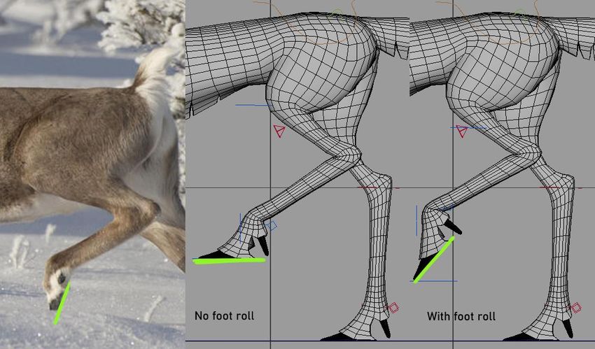
GLOSSARY

Attribute Position associated with a node, holding either a value or a connection
to another node. Used to control the functions of a node.
Edge flow Modeling practice that ensures polygon edges follow the shapes and
curvature of the 3D model. Essential in creating animatable models.
Bind skeleton The main joint hierarchy of a rig to which the topology is skinned
to.
Driver In rigging, used in reference to systems that are used to influence other
systems, e.g., a joint that is used to move another joint.
Dynamic simulation In computer graphics, a process of creating movement in
an object or a character through computer simulated physics.
FK (Forward kinematics) Basic kinematic chain where influence is calculated in
hierarchical order, parent node influencing its child nodes (i.e., elbow movement
affects the hand).
Game engine A software framework or a development software used to develop
games, i.e., Unreal Engine, Unity.
Gimbal lock Occurs when two of the three axes of a gimbal mechanism are
driven into parallel configuration, applying the same rotation to the target, and
locking it into two-dimensional space.
IK (Inverse kinematics) A type of kinematic chain where influence is calculated
in reverse order, child node influencing its parent (i.e., hand movement affects
the elbow).
IK Solver System that creates an inverse kinematic solution and a controller
element when applied to a joint hierarchy. Calculates joint orientations.
Keyframe animation In computer graphics, an animation method where an
animator is fully responsible of creating movement on the character.
Kinematics Subfield of physics used to describe and calculate motion without
considering the forces that cause it.
Mesh Polyhedral 3D object consisting of polygons.
Motion capture Process of recording movement of an object or a person. The
motion data can be used to animate computer generated characters.
Node Data point in a 3D software that stores and records a specific type of
information of the object, such as its location and shape.
Polygon Surface plane defined by edges and vertices.
Skin, skinning Procedure to bind a 3D mesh to a joint hierarchy, allowing the
joint objects influence the shape and position of the vertices.
Stress test In rigging refers to a practice where every joint of the rig is posed to
the extreme to discover the extend it can bend in before the topology breaks.
Vertex (plural vertices) A data structure that describes the position of a point on
a 3D surface. A point where two polygon edges meet.
6

1   INTRODUCTION

Creature animation, and subsequently rigging, is a notable area in game design
as various monsters and animals appear in games as both side and boss
characters. In the case of imagined beings with speculative anatomical features,
it can be challenging to build a rig system that enables anatomically accurate
animation. This paper aims to examine the role of anatomical knowledge as a
part of 3D creature rigging process and how it can be used to guide rigging
choices to create custom rigs that work towards creating believable and unique
creatures for game animation.

This is done through creating a custom rig for a creature character and analysing
ways to define a plausible anatomical framework for it to assist in selecting and
implementing rig controls that enable animating believable movement. The focus
is on rigs intended for keyframe animation, and therefore rigging for productions
utilizing motion capture or dynamic simulations will not be discussed. The case
subject is work commissioned by a client, which defines the technical framework
and creative boundaries of the production. This paper is not a part of the
commission.

Research on rigging conventions and solutions is performed through independent
analysis of rigging resources created by various industry professionals, including
literature and online tutorials, as well as by examining existing creature and
animal rigs that are made available to the public. As the creature in question is
animal-like in appearance, anatomical analysis is done with the aid of veterinary
medicine databases and existing research on relevant animal anatomy. Some
personal research on visually discernible animal characteristics is done using
photographic and video material where applicable.

The results of the production are assessed together with the client, with emphasis
placed on client satisfaction. Evaluation of the suitability of the implemented
solutions is performed both during the production and when the rig is completed.
The main rig usability evaluation is performed independently by the client through
7

animation and stress tests, though meetings were arranged to discuss potential
problems and changes where required.

2   CASE BACKGROUND

This chapter outlines the framework of the study and presents the client brief that
guides the production of the example rig. The case subject of this paper is a
creature rig commissioned by an independent client. As such, the production of
the rig is a subject to goals and limitations determined by the brief, and all
solutions and system implementations on the rig are to be done with the
expectation that they are suitable for the production pipeline of the client.

The brief includes creating a custom rig for an existing creature character model,
with emphasis placed on natural movement and consideration of the anatomical
realities of the creature where applicable when creating control systems.
Information of the story setting, character background and design principles of
the creature were included in the brief and were taken into consideration during
rigging as necessary. All background information not directly concerning the 3D
model and the subject of this report is under non-disclosure agreement and will
not be discussed in this paper.

According to the brief, the creature in question is a magical amalgamation of
various real-life animals, carrying anatomical semblance and behavioural traits
from them but having an individualized musculoskeletal system. Therefore, while
real animals are to be used as a source of reference, the locomotive capabilities
of the creature need to be considered based on the anatomy of the creature
itself. The animals featured in the design are presented in Table 1, including the
key locomotive or design features they bring to the visual design. These features
are discussed in the paper where they are relevant to the rig systems.

Table 1. Client brief breakdown.
 Animal              Feature

8

 Reindeer          Overall main design influence.
                   Foot and leg anatomy.
                   Gait.

 Barn owl          Eye placement.
                   Head stabilization.

 Least weasel      Torso anatomy.
                   Tail anatomy & movement.
                   Posing and motion inspiration.
                   Teeth & skull structure.

 Adder             Proportionate tongue length.

 Humanoid          Additional anatomical influences.

Relevant technical aspects outlined by the brief include the ability to export rig
animations to a game engine, in this case, Unreal Engine 5. In broad terms, for
the rig to be exportable, it must not have systems that are not driven by joints as
only animation data associated with a joint can be brought into the game engine.
This places some limitations on what systems are available for use and how they
can be implemented into the rig.

During production, the client participated in testing sessions where necessary,
and provided feedback upon request to ensure the product is suitable for the
production pipeline.

3   RIGGING PROCESS

This chapter discusses basic principles of 3D rigging and presents the production
of the creature rig. It explains how certain anatomical mechanisms were
translated into rig systems, describing anatomical realities relevant to the
production, and examining the systems that were implemented into the rig. The
usability of the rig and the technical limitations outlined by the brief will be
considered where they affect the systems selected for implementation. The
process description is divided into sub-chapters based on the anatomical
mechanisms or rigging systems so that anatomically or mechanically similar
areas are discussed together.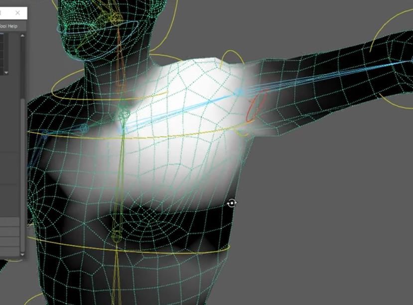
9

In computer generated graphics, the term rigging refers to implementation of a
system of control mechanisms that allows an otherwise static geometry model to
be posed and animated by an animator Jones 2013, 1). It is a process that can
be likened to digital puppeteering. Same as a marionette has strings that are
used to control the poses and movements of the puppet, a rigged 3D character
can be posed using digital controls such as joint objects and object behavior
attributes and constraints.

The basic element of a rig is a joint object hierarchy commonly referred to as the
skeleton, connected to the topology in a process known as skinning (Figure 1).
During skinning, the vertices of the geometric model are assigned weights that
determine which joints in the hierarchy they follow.

Figure 1. Example of a 3D skeleton structure for a human model (Autodesk no date c)

This allows the model to be posed by manipulating translation, rotation, and scale
of the joint objects, often done using controller objects. The weights are assigned
on a scale of 0-1, where a value of 1 means the vertex inherits the joint
transforms fully, and a value of 0 means it is not affected by the joint (Figure 2).
10

Figure 2. Skin weight visual representation in Autodesk Maya as a grayscale gradient where white
means a full weight value of 1, and black means no influence (Ward 2020)

Single vertex can theoretically be influenced by as many joints as necessary, but
typically for game rigs the amount is kept as low as possible to conserve the
data. Additional systems can be built on top of the base structure to improve the
range of movement of the rig and to make it more intuitive to manipulate. These
systems are selected and implemented based on the individual requirements of
the production.

Anatomy is an integral part of character rigging, as understanding of the
structures of living creatures is necessary to mimic these systems accurately with
digital mechanisms. However, as a computer generated rig exists within digital
space, subject to computer processing limitations, replicating realistic anatomy
systems can be needlessly complex, as an excess number of joints and systems
can negatively affect the performance and maneuverability of the rig. It is
therefore more effective to find digital solutions and systems that can simulate
natural movement. This can be done through biomechanical analysis. (Jones
2013, 19.)

Biomechanics is the study of biological systems through mechanical principles,
offering insight to joint kinematics, tissue functions and center of gravity during
movement (Innocenti 2018). This analysis of natural movement can be used to
simplify anatomical structures into mechanical systems, creating adaptations of
the anatomical reality as movement inputs that can simulate natural motion
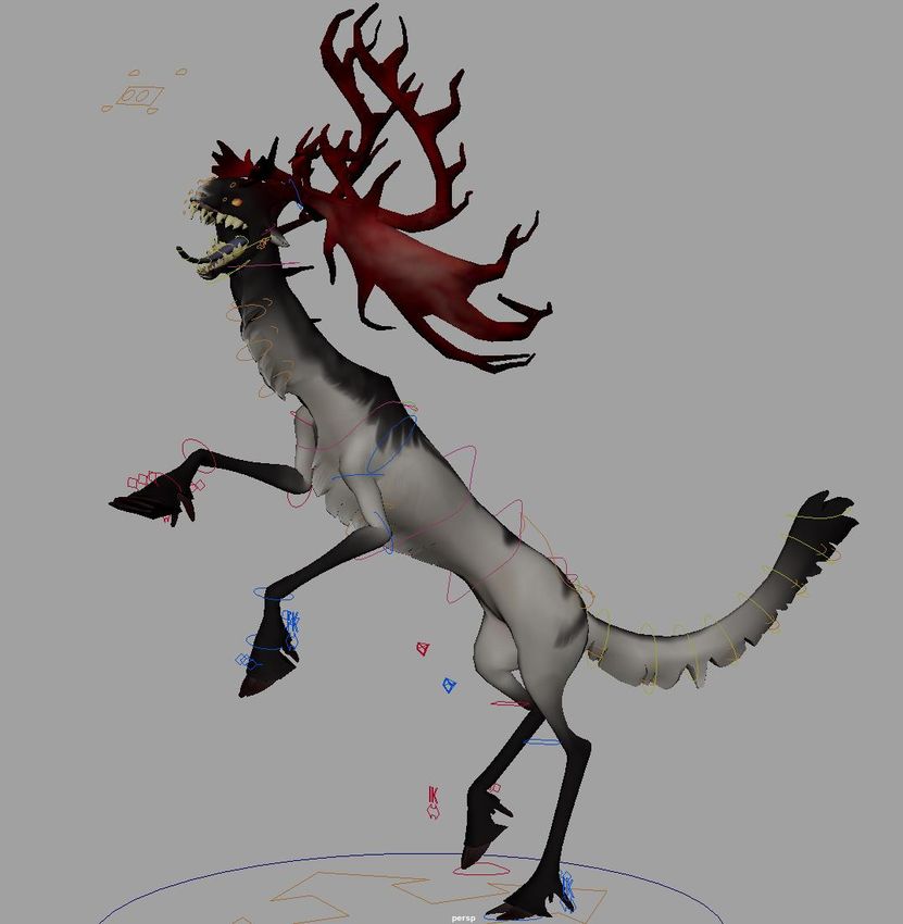
11

without the inherent complexity of a natural mechanism (Jones 2013, 19). For
example, a human neck has seven vertebrae, but in a standard 3D human
character rig one neck joint is sufficient to achieve a range of motion that is
similar to that of a real human neck anatomy, therefore appearing natural despite
being unrealistic (Ward 2019).

When the goal is to create a character model that can perform natural
movements and appear believable, anatomical, and biomechanical
understanding creates a framework within which decisions of digital joint
placement, surface deformations and overall behavior of the rig can be justifiably
made (Jones 2013, 18).

3.1   Discovering the skeleton

To begin the rigging process, it was necessary to determine the placement and
number of joints that would act as the base skeleton of the creature (Figure 3).
The brief included concept art of the intended skeletal structure of the creature
and this diagram was used as a general reference for the joint placement, though
additional testing was required to discover joint count and placement in areas
where they would differ from the imagined natural structures.

Figure 3. Concept art of the skeleton of the creature. Pink dots represent possible rig joint
placement.

Groundwork for joint tests included studying rigging tutorials from industry
professionals and analyzing various quadruped creature rigs available on online
12

platforms such as Sketchfab. These solutions were compared to real animal
skeletons and joints to uncover patterns in how certain areas of the anatomy are
typically built and where potential challenges could be expected. Using this
knowledge, test skeletons were created to discover suitable joint placement for
the creature and to uncover any potential problem areas.

During the tests, it was determined five joints in addition to the hip joint would be
enough to achieve a sufficient range of motion out of the spine while also being a
comfortable amount for the animator to work with. Five tail joints proved to be
insufficient for control that was desired over the tail, whereas nine joints provided
a lot of control, but the amount was deemed unnecessarily high for the scope of
the project. Seven joints, with an eighth to control the fur at the tip, was
determined to provide the desired flexibility while also being reasonable in terms
of overall user-friendliness and game engine performance. For the neck, five
joints were enough to ensure a wide range of motion and flexibility (Figure 4). In
the final build, a sixth joint was added to the spine to be used as an anchor for
the scapula joints and to maintain an even distribution between the spine joints.

Figure 4. Extreme pose to demonstrate flexibility of a test rig.

The leg build required significant amount of testing, as for a quadruped all limbs
are essential to movement and therefore insufficient or inaccurate leg structure
13

could have significant consequences to the functionality of the rig. From the
shoulder to the wrist and the thigh to the ankle, defining the build was
straightforward, as it follows the joints visualized in the concept art for the
creature. A notable difference to the natural system is the addition of a joint to
present the scapula where no biological joint is present. On a standard humanoid
rig, the scapula is usually omitted in favor of a joint representing the clavicle, as
anatomically, the primate scapula is located at the back of the thorax and does
not move independently from the clavicle. On a quadruped creature, however,
the scapula is located on the side of the thorax and is mobile to increase the
length of the stride. (Fletcher 2019.)

The creature scapula resembles that of a large herbivore and as equine anatomy
is well-documented, it is possible to use horse musculature as an estimated
guide to the scapula movement. Equine scapula has several muscle groups
attached that are used to elevate the shoulder, as well as move it towards the
head and rear. (Lloyd no date.) This can also be verified by examining
photographic footage of moving animals. Simplification of the movement patterns
produced by the author can be seen in Figure 5.

Figure 5. Simplification of scapula movement patterns.

From this, it can determine the scapula, although free moving, moves the
humerus in a pendulum pattern. This pattern can be replicated in the rig by
placing a joint to the estimated proximity of the middle of the dorsal border of the
scapula and placing it as a child of a spine joint and a parent of the humerus joint
in the hierarchy (Figure 6).
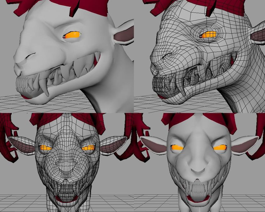
14

Figure 6. Demonstrating scapula movement in a test rig

The joints for the feet went through several tests, as multiple builds that mimicked
anatomical joint placement proved to be impractical for animation. Figure 7
illustrates the first iteration of the joint system for the front feet. In this setup, the
number of joints connecting dewclaws to the wrist represents the biological truth
more closely. However, in the rig, the joint between the wrist and the dewclaws
was unnecessary as the desired range of motion for the dewclaws was achieved
with the dewclaw joints alone.

Figure 7. First iteration of foot joint system and how it matches biological joints on a reindeer foot
(Li et al 2020)
15

The first iteration of the foot joint hierarchy also included a joint for the purposes
of manipulating topology representing the fur covering the foot. This joint was
dropped after testing as it was deemed unnecessary for the requirements of the
production.

The final foot joint system has the toe joints parented to a single foot joint, and
the dewclaw joints to the wrist and ankle respectively (Figure 8). This setup
allows natural movement of the ankle and wrist joint, and the individual
movement of the visible hooves and dewclaws, as well as provides additional
flexibility for the foot between them. Skinning a portion of the mesh representing
fur to follow the toe joints ensured the fur and hoof topology would not separate
during movement.

Figure 8. Final foot joint setup for the creature. (Kontinen 2022.)

Similar setup has been used in other commercial productions, such as Disney’s
feature film Frozen and a Mediamarkt advert by Band VFX (Harding 2020).
Though these were discovered later and did not directly influence the build and
present some differences in the choice of joint count, they affirm the usability of
the general joint placement and hierarchy. Figure 9 illustrates the joint system
utilized in the Mediamarkt advert.
16

Figure 9. Reindeer rig from Mediamarkt Christmas advert by Band VFX (Band VFX n.d.)

For the face, two possible builds were considered, a system driven with joints and
a system driven using blend shapes (also known as morph targets). Blend shape
systems allow the base mesh to assume the shape of its target mesh, providing
that the base and target mesh vertex orders are identical (Autodesk n.d.). In
practical terms, this means a copy of the rig mesh can be modeled to express a
certain action, i.e. lips lifted in an aggressive snarl, and the base rig mesh can
assume this shape by adjusting the influence the target mesh has on the base
mesh vertices. Joint-based face rigging requires the animator to adjust several
controls manually to achieve certain expressions, whereas a blend shape-based
rig enables animating facial expressions with predetermined shapes. This
provides accuracy and efficiency. Both joint and blend shape systems were
tested with the client after which the client requested a blend shape based rig, as
it would result in more accurate deformations and be more suitable for the
animation workflow of the project.

In addition to skeletal joints, tests were done to discover an appropriate solution
to adding mobility to the fur of the creature so that it may be animated or
repositioned to mitigate clipping when posing the head and the tail. Several
systems proved insufficient to the type of movement desired or did not perform
well with the flexibility of the creature. Final solution was to add a joint at the base
17

of selected fur patches, with a child joint placed close to the tip of the fur. The
topology would then be skinned to these joints in a manner that allows the fur to
be rotated either from the base or the tip. These joints were parented to spine
joints corresponding to their location (Figure 10).

Figure 10. Neck fur joint hierarchy and exemplification of deformation possibilities

Creating separate joint structure for every individual strand of fur would have
resulted in excess number of control points, so the placement and number of
joints was in this case determined together with the client to ensure enough
control for the requirements of the project while keeping the amount of control
points to a minimum to conserve data. This setup means some of the fur strands
had to be combined under a single control and move in unison. For instance, all
fur strands under the chest were skinned to a single joint chain and cannot
therefore be moved individually. (Figure 11.)

Figure 11. Fur strand skin weights (left), white area represents weight value of 1, black 0.
Demonstration on weight influence on topology when joint is rotated (right)
18

To prevent a look where the fur moves as a unified block, the strands were
weighted to the joints differently so that a portion of the belly fur remains almost
static when the joints are rotated. This way, it should not be immediately apparent
the entire bulk of the belly fur is controlled with only two joints when animated.

3.2   Skin weights

Skin weights determine how the topology responds to manipulation of the joints.
It is, as the name suggests, a way to mimic skin behavior. The number of vertices
and the edge flow of the model determine how successfully the topology can be
skinned to follow natural movements and skin behaviors. Generally more vertices
means more allowance to mimic natural skin movement. The creature can be
classified as low-poly, meaning it has a relatively low number of vertices, and
therefore cannot perform absolute anatomical realism, so the goal was to achieve
the closest possible semblance while preserving clean folding of the topology.

As skin follows muscle movements, an approximate muscle map was created for
the creature to define which portions of the topology should responds to which
joints (Figure 12). This map was built referencing the musculature of the various
animals that function as design inspiration for the creature, identifying similarities
and estimating logical origin and connection areas for the main muscle groups.
Only the top layer of muscles was considered, as this is something that
influences the skin. This map was not extended to areas with minimal skin
movement, such as the metatarsus area, and the face was left for a later stage
due to not being skinned to joint.
19

Figure 12. Muscle maps created on top of the creature final concept art

In addition to the speculative muscle map, footage of relevant animals in motion
was examined to determine how the skin moves when different bones and
muscles are in motion. The topology in the thigh area presented some challenges
in allowing free movement of the leg while preserving some of the visual rigidity
of the pelvic area.

First pass of the skinning was completed after the creation of the final skeleton,
but before any rigging systems were implemented. Thus, the effect of the rig
systems on the topology would be immediately visible and could be assessed
while building, instead of afterwards. A portion of the skin weights was updated
after building the rig systems to better function with the movements of the
mechanisms.

3.3   Pelvis & spine

Biologically, the spine is a vertebral column originating from the pelvis and has
significance in offering the body support and structure that allows free movement
and flexibility (University of Maryland Medical Center 2003). Vertebrates are
associated with a spine that is similar in the base structure, though they may
possess morphological differences that define the extent of the mobility of the
spine (Boundless 2021).

For the creature rig, the relevant reference subject for spine structure and
mobility was defined to be a least weasel by the brief. This implies notable
20

mobility, as most mustelids have a flexible spinal column accredited to thin
spinous processes in the thoracic vertebrae (BBC Earth 2021).

In rigging, a typical solution to support spinal flexibility that does not rely on an
extensive number of joints is a spline IK setup. It enables stretching and
squashing of the spine and connected topology. In a spline IK setup, a type of a
curve is created to match the IK spine joints and connected to an IK handle. The
length information of the curve can then be used to assess when the spine is
being stretched or squashed by the controller handle, and this information can be
used to match the joints bound to the topology to move to match the new length
of the IK spine. Additionally, a spline IK system offers gradual flexibility to the
spine as the spine joints follow the shape of the curve, allowing for quick posing
with natural effect without the need to pose each joint individually. (Jones 2013;
Ward 2021.)

This system was implemented into the creature rig to enable quick and natural
posing of the spine. The system was enhanced with the application of a volume
preservation system that automatically scales the topology in relation to the
length of the spine so that the creature appears thinner as it stretches and bulkier
as it squashes. Though this may result in unnatural appearances in extreme
static poses, it is an essential addition to achieve natural movement during
animation. The ability to squash and stretch a character during movement is
defined as a key principle of animation, as it can be used to make the movement
appear fluid and realistic (Patmore 2003).

Another essential feature to enable natural movement of the spine in a rig is the
ability to move the pelvis joint independently from the spine joints to allow leg
movement to affect the hips but not the spine. Biologically, independent
movement of the upper and lower body is possible due to complex muscle
systems affecting the vertebrae. In rigging, however, joints are connected through
a hierarchy structure, inheriting transform values from their child or parent objects
in accordance with kinematic principles. Therefore, a special joint structure is
required to allow independent movement of the pelvis. This is colloquially known
21

as the free hip and can be implemented by adding a joint at the base of the spine
to act as a root joint. (Allen et al. 2008.)

Figure 13. Spine joint hierarchy of the rig

As illustrated by Figure 13, the spine base consists of joints called CoG (center of
gravity), Hip and Back#. CoG joint acts as a base root for the entire joint
hierarchy, including the hind legs (L_Femur, R_Femur) and tail (Tail01)
hierarchies, enabling movement of the lower body of the creature. The hip joint is
a child of CoG, parenting the spine (Back01) and upper body (not visualized).
Thus, movement of the CoG travels through to the Hip joint and its children, but
the movement of the Hip does not affect the movement of the CoG, creating a
system where the pelvis has two control points for lower and upper body
movement respectively. In an event transformation needs to be applied to the
entire body, the joint Root is used, as it is the parent of CoG.

It should be noted that while the joint is named after center of gravity, it bears
little semblance to the concept in case of the creature rig. In a stationery human,
the center of gravity lies approximately in the middle of the pelvis, specifically
around the anterior of the second sacrum (Bhagat et al. 2019). Therefore, the
free hip joint is often called CoG in rigging as it deals with the hip and enables
animating weight shifting with ease (Allen et al. 2008). In quadrupeds, particularly
large herbivores, the center of gravity tends towards the front of the animal, as
the forelimbs bear most of the weight of the animal (Bhagat et al. 2019). Thus,
22

what is called CoG in the rig is not the actual center of gravity the creature would
possess.

3.4   Legs and feet

Reindeer (Rangifer tarandus), also known as caribou, is the key anatomical
reference for the leg anatomy of the creature. The hind feet of the creature are
modeled to closely resemble that of the reindeer and are expected to move as
such. The front feet are more fantastical, carrying structural inspiration from
humanoid hands, resulting in three toes instead of two, and presenting bone
length relations that carry more resemblance to digitigrade species. Despite the
anatomical differences, the look and feel for the movement of the front feet
should, according to the brief, be reminiscent of that of the reindeer. The front
feet are also not to have hand-like mobility and should function as strictly
quadrupedal limbs only.

When building rig systems for legs with clear anatomical resemblance to an
actual animal, it is necessary to consider the anatomy and locomotion of the
animal to determine what functions the rig is required to fulfill and what type of
build meets these requirements.

Reindeer are unguligrade, meaning they walk on the very tip of their toes, with
phalanges off the ground. The hoof, which is often perceived as the foot, is in fact
the keratin nail of the digit. (Fletcher 2019.) Reindeer hoof has four digits, two
toes facing forward and two dew claws at the back. As opposed to some other
members of the unguligrade family, such as bovines, the reindeer dew claws
have functional significance. Like the toes, the dew claws can spread against the
ground, offering additional surface area for walking, and curl inwards in a shovel-
like shape to assist in digging when the foot is flexed. (Hull et al. 2021.) Examples
can be seen in Figure 14.
23

Figure 14. Examples of movement range of the reindeer hoof (Kiviminna 2011; Machová 2006)

The uniqueness of the foot posed challenges for the rigging process, as there
were not any direct references for a suitable joint structure readily available. The
ungulate foot is often an area that gets overlooked or built in an improper manner
in amateur 3D rigs, and rigs from high-end professional productions are rarely
available or presented with joints revealed.

In improperly built rigs, a common problem is the main angle the joints bend, or
fail to bend in, during movement. A particular problem often observable in
ungulate rigs and animation is the rigidity of the fetlock joint and consequently the
use of knees as the main shock absorber (Figure 15). This can lead to
animations that the viewer can perceive as unnatural, stiff, or bizarre, impeding
their ability to connect with the creature (Ries 2020).

Figure 15. Examples of ungulate rigs with no proper flexibility in the fetlock joint and inaccurate
joints (Simonov 2018; Bompotas 2016)
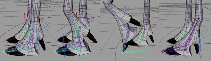
24

The fetlock is best observed and documented on horses, and while there are
some differences between the horse and the reindeer joint, the overall function is
the same and can be used as an example. The fetlock is among the most mobile
joints for equines, having a range of motion at about 120 degrees in flexion and
extension, particularly during intense activity such as jumping. Conversely, the
pastern joint, located between the hoof and the fetlock, is less mobile at only
about 30-degree movement. (Bertone 2016.) As the animal moves, the fetlock
acts as the main shock absorber, supporting the joints further up the limb.
Visually, this results in a look where the ankle area can be significantly bent
(Figure 16).

Figure 16. Examples of unguligrade fetlock position during movement of horses (left) and reindeer
(right) (Fei no date; Taskinen 2014)

This can be problematic to rig, as the fetlock needs to bend in both directions
during movement. For an FK system this is not a challenge as the joint
orientation can be manually adjusted on all axes. Walk and run cycles are often
animated using IK, which uses solvers and preferred joint angles to determine
which way the joint bends at any given position. If this system is not built
correctly with sufficient supplementary attributes, the joints can remain stiff or
bend in an unnatural manner.

For the creature rig, this problem was solved by supplementing the base IK
systems with what is known as a reverse foot system. This system is a separate
joint chain that consists of additional ankle, toe, and heel joints that can be used
to drive the main IK skeleton foot joint rotations with the use of hierarchy and
connections (Figure 17).
25

Figure 17. Showcasing the reverse foot joint chain on front leg (IK and bind skeleton invisible)

The reverse foot essentially functions as a multi-hinge lever attached to the wrist
or fetlock that is used to peel the foot off the ground gradually one joint at a time
both forwards and backwards, effectively creating both flexion and extension
movements in the foot joints (Figure 18).

Figure 18. Showcasing reverse foot setup acting as a lever to alter the position of the front foot
joints

For this to be possible, the IK driver skeleton requires additional joints to stabilize
the foot as well as supplementary single-chain IK solvers to calculate the motion
(Figure 19). With some further additions, the system can also be set up to control
other movements, such as the foot banking and twisting. Setting these systems
up can be complicated and needs to be done carefully so that the reverse foot
can drive the IK skeleton accurately. (Ward 2021.)
26

Figure 19. Showcasing the additional IK joints implemented to balance the foot (front). Seen in
back base bind skeleton build

What the reverse foot system means in terms of fetlock mobility is that the ability
to roll the hoof forwards and backwards can be used to introduce bending in
areas the IK solver setup otherwise leaves stiff, namely the fetlock and pastern
joints (wrist and toes on front foot) (Figure 20).

Figure 20. Demonstration of foot roll attribute effect on the angle of the hoof during stepping
motion (Quinton 2014)
27

Additionally, the ability to bend these joints allows the legs to extend further
without causing the IK joints to overextend or pop out of alignment (Figure 21).

Figure 21. Example of foot roll preserving natural look when the leg is extended backwards
(Antikainen 2012)

These movements can be used to animate both flexion and extension into the
leg, enabling the use of fetlock as the main shock absorber joint in motion, as
well as ensure the hoof can be posed in a more accurate manner in all stages of
the gait.

IK systems for quadrupedal limbs require a different approach than human
(bipedal) limbs. While the base anatomy between quadruped and biped limbs are
similar and the joints bend in the same direction, typically, in quadrupeds, the
metatarsal bones are elongated, and the heel does not make contact with the
ground (Figure 22). Additionally, on quadruped front legs, the wrist is typically
less mobile than a biped wrist.
28

Figure 22. Comparative anatomy of plantigrade, digitigrade and unguligrade leg (Wikipedia
Commons 2018)

From a rigging standpoint, this means that there are more joints in the limb chain
that need to be accounted for as opposed to a biped rig. Between the shoulder
and the wrist, and the thigh and the ankle, there are two joints that need to be
accounted for, whereas in a human leg, only the knee and elbow joint rotation
needs to be considered in the creation of the IK solution. (Ward 2020.) IK
systems are mathematical constructs, not anatomical models, and do not
automatically account for natural joint mobility. Therefore, to ensure the joints
bend in the correct direction when controlled by IK, they should be built in a
slightly bent position. This way, the IK will use the existing bend as the preferred
angle, and the leg will compress in an anatomically correct manner when
positioned. (Ward 2019.) In situations where this is not possible, other measures
need to be taken to ensure the limb can be positioned naturally.

While this was enough to bring a modicum of natural movement to the legs of the
creature rig, further adjustments were necessary since the proportions of the legs
resulted in uneven compression between the upper and lower segment of the leg.
These segments can be defined as a system of opposing hinge joints (shoulder-
elbow, knee-hock) where the amount of turn between each arm defines the
position of the leg (Figure 23).
29

Figure 23. Leg segments in the joint hierarchy.

Using a specific type of IK solver called the spring solver includes a spring angle
bias setting which allows the customization of the relation of the angle in the
upper and lower section of the limb. With this adjustment it is possible to
compensate the length discrepancies between the leg segments by making the
lower section compress more than the upper section.

However, the spring solver has some drawbacks. The common build using spring
solver and a reverse foot system requires the IK handle of the solver to be
parented to the foot control object instead of being constrained to it. This ensures
it responds to movements of the control object but is not restricted to it, allowing
the foot to rise off the controller when the reverse foot attributes are activated.
Thus, as the handle sits inside the main control group hierarchy, it receives
rotation values when the rig is rotated on the Y axis from the master or the root
control. This rotation value causes the IK driver joints and subsequently the legs
of the model to move out of alignment.
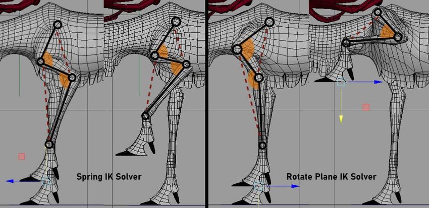
30

Quick research uncovered a plausible way to fix this problem by automating
counter movements into the rig using nodes. IK handles have native twist
attributes that are used to roll the entire IK chain from the handle up. This creates
a similar effect as the inherited Y rotations and can therefore be used to counter
them. The Y rotation of the master and root controls are linked to the twist
attribute of the IK handle. To ensure rotation values from both controls are
calculated, they pass through a specific calculus node before they are fed into the
handle attribute. This node sums up both Y rotation values to form a single value
that can be used to drive the twist attribute. This value is opposite and equal to
the amount of rotation in the controller objects, countering the additional rotation
value the handle receives. (Point on Palley 2019.)

It should be noted that the twist value of the handle and the rotation value of the
control are not exact by decimals, and some movement travels through to the
joints. This can be observed in the rotation values of the hock joint in the main IK
joint chain. While the amount is negligible in most instances as it cannot be
observed visually and does not interfere with other functions of the leg, for
situations where a clean rig with no leftover values is required, this is not an
optimal solution. Using rotate-plane solver instead of a spring solver for the driver
skeleton IK handle removes the issue, as this type of solver will always attempt to
keep the joints in the chain on the same plane (Autodesk n.d.). However, the
rotate-plane solver does not have angle bias settings, which results in the back
legs appearing stiffer (Figure 24).
31

Figure 24. Comparison between the amount of movement achievable from the back leg before
the upper segment of the joint chain becomes unresponsive to further compression

For the front legs, the rotate-plane solver causes a significant drop in the
responsiveness, possibly due to the length ratios between upper and lower
section of the solver. It would cause the upper leg segment to dislocate before
any notable compression could be applied to the lower segment (Figure 25).

Figure 25. Demonstration of spring solver and rotate plane solver compression
32

A meeting with the client was held to discuss the benefits and drawbacks of each
solver and through animation tests, it was determined the issues caused by the
spring solver would be unobtrusive within the scope of the project, whereas the
rotate plane solver would effectively make the rig unusable. Therefore, the
above-mentioned workaround was implemented into the spring solvers.

3.5   Face and jaw

The brief outlined two main objectives for the head and face rig. The creature is
to be able to perform animal-like threatening, ferocious expressions, and all
topological deformations and skin behaviors should appear natural when
considering the anatomical realities of the creature. Additionally, a list of required
expressions was provided.

As the head of the creature is its most unique feature and carries no true
resemblance to any actual animal, the appearance of these expressions needed
to be designed prior to implementing the blend shapes. Some concept art of the
expressions of the creature existed, but it proved to be insufficient reference as it
did not match the final version of the design of the creature.

To build these expressions, the anatomical mechanisms driving the facial actions
on a realistic creature were studied to gain an understanding of how these
structures might present themselves on the fictional being. To be able to make
comparisons between the fictional and the realistic, the facial anatomy of the
creature was examined. This way, it was possible to determine the framework for
how the masses move as the soft tissue is pushed and pulled by muscles on top
of the skull.

Tools used in determining the underlying anatomy of the head were character
design notes received from the client and studies of anatomical diagrams and
photographic references of real animals with similar features and structures. This
knowledge was then used to design an array of target mesh shapes that mimic
the presence of natural structures. This process will be described in detail by
33

using a snarling expression as an example, as this expression had priority in the
brief and required particular attention.

Anatomical research revealed that a snarl, or sneer, is defined as an act of
pulling the nasolabial levator muscle attached to the upper lip and tightening the
caninus muscle (known as levator anguli oris in humans) (Camerlink et al. 2018).
On the visible surface, a snarl is characterized by wrinkled skin around the nose
and, oftentimes, the revelation of teeth. The skin wrinkles generally appear at the
root of the nose, on the nose bridge and nostril area, depending on the shape of
the head, size and placement of the muscles and the amount of skin that moves
(Figure 26).

Figure 26. Various snarls (horse, wolverine, human) presenting different skin behaviour based on
skull shape, skin and musculature (15 minute horse fix 2013; Distinctly Montana 2021; Wikipedia
Commons 2006)

Further research suggested the nasolabial levator and caninus muscles, while
present on various mammals, vary in exact shape and placement depending on
species. The skull shape and teeth of the creature are inspired by a least weasel
(Mustela nivalis), but it proved difficult to find muscular diagrams of these
muscles on mustelids. Therefore, carnivorous species in general were used as
the main source of reference for muscle placement.
34

Figure 27. Nasolabial levator muscle (left) and caninus muscle (right) location on a canine
(IMAIOAS SAS 2021)

On a canine, the nasolabial levator is present on the wing of the nose, connecting
to the upper lip and side of the nostril and attaching to the base of the nasal bone
(Vet-Anatomy n.d.). The caninus muscle originates on the maxilla, on the back
edge of the canine fossa and is attached to the skin on the upper lip and wing of
the nose, as portrayed in Figure 27. (Vet-Anatomy n.d.) These connections
create a pull from the lip towards the cheek and frontal bone.

With this knowledge, it is possible to build a snarl on an imagined creature by
considering the plausible influences of the nasolabial levator and caninus
muscles on the skin of the creature. When examining the character design notes
provided by the client, it is evident that the nasal bones of the creature are short
and withdrawn (Figure 28).

Figure 28. Creature skull shape concept art

This implies the nose consists of soft tissue and the nasolabial levator muscles
are attached rather high up on the forehead, meaning the entire mass of the nose
35

bridge is subject to movement and folding (Figure 29). Determining the source
and direction of the main forces affecting the face during snarling actions allows
moving relevant areas on the model in the correct direction with consideration to
the imagined skull surface underneath.

Figure 29. Estimation of the position and angle of movement of the key muscle groups used for
snarling

The amount of wrinkling could then be determined by considering the elasticity of
skin and preservation of volume, as well as by referencing photographic material
of animals performing similar motions. Some simplification was necessary as the
polygon count of the creature does not support high level of detail (Figure 30).
36

Figure 30. Finished snarl blend shape

By implementing these design steps, it was possible to discover the plausible
anatomical structures of the head of the creature and so determine the form of all
the necessary expressions. Thus, all the blend shape targets could be modeled
in a manner that mimics the presence of natural mechanisms with little need for
guesswork. Examples of these can be viewed in Appendix 1.

In addition to creating animatable features, blend shapes were used to ensure
topological deformations appear visually pleasing and natural even in situations
where the desired range of movement results in folds and clipping of the topology
that could not be resolved with skin weights alone. One such instance being the
range of movement of the jaw.

According to the brief, the maximum desired angle of the gape of the mouth
should be roughly 70°. While this movement can be performed simply by skinning
the corresponding jaw topology to the jaw joint, it results in unnatural
deformations, appearing as if the skin of the neck has lost elasticity and is being
37

sucked inwards. To get around this effect, a corrective blend shape was used to
create a version of the topology where the vertices of the neck remain more static
and create a pouch-like shape in the space between the jaw and the upper
portion of the neck (Figure 31).

Figure 31. Comparison of neck topology without (left) and with (right) corrective blend shape

To ensure the shape would trigger automatically as the jaw opens, the main
rotation of the jaw was used as a driver by connecting the x-rotation value to the
weight value of the blend shape. It was also necessary to include the x-rotation of
the head joint in the system, as otherwise rotation of the head joint would
interfere with the blend shape and cause a bulging effect if the jaw was opened
while the head is posed (Figure 32).

Figure 32. Demonstration of the neck pouch created by improper activation of the neck blend
shape
38

The head and jaw rotation values were fed into a node that calculates an average
sum of the values, which was then fed into the weight value of the blend shape
after passing through a remap node to ensure the rotation and weight values are
mutually compatible.

Figure 33. Exemplification of the neck blend shape working as intended when the head is tilted.

This way, the effect the blend shape has on the topology would be calculated
based on the movement of both the head and the jaw joint, averaging out
between them and creating an effect that resembles the natural behaviour of skin
in this area (Figure 33).

3.6   Eyes

The brief requested extensive controls over the eyes and eyelids to facilitate
animating expressions and to allow finer control over basic blink animations. In
addition to standard controls (moving the eye and eyelids), the brief included the
ability for the eyelids to automatically react to the movements of the eyeball, as
well as a system to adjust the height of the blink.

In rigging, a system where the eyelid reacts to the movements of the eyeball is
colloquially known as the “fleshy eye rig”. It is used to create an illusion of the
39

eyelids resting on top of the eyeball, making the eye movements appear more
natural and less uncanny.

Blink height system can be used to make blinking animations more organic. It can
be used to add key animation principles into the motion, such as anticipation
where an action is set up with a slight movement in the opposite direction
(Patmore 2003). Additionally, it can be used to simulate the look of eye positions
associated with actions such as squinting and sleeping. While there are ways to
incorporate intricate controls for the eye area to account for the fine muscle
movements of a realistic eye, for the creature in question, this would be too time
consuming and outside the needs of the project. A simpler system that can
achieve the visual likeness of an eye during certain basic expressions is therefore
a better option (Figure 34).

Figure 34. How eyelid position can be used to achieve certain expressions

All necessary eyelid controls, individual control over they eyelid, the fleshy eye,
and the blink height, are set up using eyelid joint rotations. This means finding a
solution where three separate systems that need to interact with one another
without causing interference. Rigging artist and animator Anthony Ward (2021)
presents one such system in his tutorial video series Rigging in Maya. In it, the
40

eyelids are controlled by a network consisting of a hierarchy of joints and a
system called “ribbon” which utilizes edge loops driven with the help of hair
simulation nodes. The ribbon system controls the eyelids and the fleshy eye, and
the joints enable the ribbon to be moved up and down to adjust the height of the
blink. This system functions according to the requirements of the brief but needed
to be modified for the creature rig as the rig cannot utilize the ribbon solution as it
is a non-joint based system.

In the modified system, the eye and eyelids joints are positioned in the center of
the eye, along with a driver group. This driver group is used to control the upper
and lower eyelid joint rotations simultaneously, while a separate controller setup
is used to manipulate the lid rotations individually. This system enables the lids to
be posed and the posed lids to be further positioned with an attribute slider from
the main eye control. Additionally, the main eye joint is set up to feed a fraction of
its rotation to the individual eyelids to incorporate the fleshy eye effect. This
means a single eyelid joint is receiving three different rotation inputs, so it is
necessary to transmit them through a node that outputs a single value that is the
sum of all the inputs. The node graph can be seen in Figure 35.

Figure 35. Eyelid control setup in Maya Node Editor
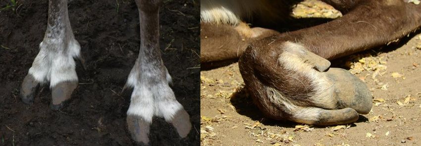
41

Figure 36. Topology deformations showing the eyelids unposed, in basic blink, with blink height
up, and with blink height down

As can be seen in Figure 36, this setup allows the eyelids to be positioned into a
blink, and this blink can be posed even further as topology allows. This gives the
animator the ability to mimic the look of natural eyelid movements and easily
adjust the posing.

3.7   Ears and antlers

While the ears of the creature do not carry a distinct resemblance to any specific
species, they take general inspiration from animals and are therefore expected to
be mobile and able to perform both listening actions as well as emphasize
expressions. Several species of mammals have a network of muscles attached to
their ears, allowing them to control the direction as well as the rotation of the
pinna of the ear without moving their head (Szunyoghy et al. 2006). This means
the ears can have several shapes and silhouettes depending on which direction
the animal is listening to, as the pinna folds and extends according to the
movements, as can be seen in Figure 37.

Figure 37. Examples of various ear positions for a deer (Jolly 2021)
42

This presents a challenge in rigging, as using a single joint control to rotate the
ear in different directions will not affect its shape. The full ear, rotated at the base
to point backwards, will simply appear as the ear in base position with its tip
pointing towards the back. This does not convey the image of an animal listening
to what is behind it. For a more natural movement and better readability of
intention behind the movement, the ear pinna should respond to the movement
by twisting forwards, preserving the cup-shape of the ear, and directing it
backwards. If an attempt was made to rotate the ear into two different directions
on a single joint to affect both its direction and shape this way, there would be a
risk of gimbal lock or breaking the topology.

Therefore, since the issue at core appeared as the requirement to apply double
rotations to the ear to achieve a lifelike range of motion, a double joint setup was
used. The base joint, parented to the head joint, would move the entire ear from
the base, allowing it to rotate freely in all directions. The second joint, parented to
the ear base, would be used to specifically alter the shape of the ear by skinning
the vertices around the upper front edge to it. When rotated forward on the X-
axis, this joint would allow the ear to curl leading from the front edge. Additionally,
when rotated up on the Z-axis, the ear would widen. With this setup, the ear can
be both rotated at the base to direct it as well as the shape manipulated without
these two functions interfering with one another, as seen in Figure 38. It should
be noted this does not comprehensively mimic the actual anatomical mechanism
but is rather used to achieve the visual likeness of the natural rotation of the ear.
43

Figure 38. Examples of how the ear setup can be used to accentuate the direction of sound the
creature is listening

To ensure the functions of the second joint would be user-friendly, the X and Z
rotations were connected to float attributes on the main ear control named “ear
fold” and “ear spread” respectively. This setup allows the rotation values to be
controlled through a numeric value that can be assigned a minimum and a
maximum. This ensures the joint rotations never go below or over the desired
amount, preventing instances where the ear topology collapses inside of itself.

Although antlers naturally lie static on the head, it was requested by the client
that a possibility to move the lower pair would be included in the rig. Since this
character is to be used in a cinematic animation, it will always be animated
towards a single camera. Therefore, it is possible to bend the character in
positions that can break the rig or cause clipping if the final render in the camera
doesn’t show it. Hence, there may be situations where the animator might desire
to move the antlers slightly either to prevent them from clipping inside the body of
the creature or to achieve certain camera effects.
You can also read