Installation Guide ERV Series - 69-ERV-Install 071516 - Lifebreath
←
→
Page content transcription
If your browser does not render page correctly, please read the page content below
ERV Series
         Installation Guide

                               Setting a new standard for
                          energy efficient, clean air homes

                                      511 McCormick Blvd
                         London, Ontario Canada N5W 4C8
                                             519.457.1904
                           General Info / Tech Support:
                                         1.855.247.4200
69-ERV-Install 071516              www.lifebreath.com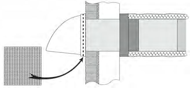
Table of Contents
Location ...................................................................................................................................... 2
Pre-Installation Notes ................................................................................................................... 3
Simplified Installation (Return/Return Method) .................................................................................4
Partially Dedicated System .............................................................................................................5
Fully Dedicated System ..................................................................................................................6
Mounting the 30ERV and 120ERV ...................................................................................................7
Hanging Straps .............................................................................................................................8
Grilles ..........................................................................................................................................9
Grille Fittings ..............................................................................................................................10
Lifebreath Weatherhood ..............................................................................................................11
Weatherhood Requirements .........................................................................................................12
Main Control Installation ..............................................................................................................13
Selecting the Ventilation Rate ....................................................................................................... 14
Installation and Operation of Wireless 20/40/60 Minute Timer: 99-DET02 ........................................15
Installation and Pairing of Repeaters: 99-RX02 ..............................................................................16
Interlocking the ERV ...................................................................................................................17
Installer Selectable High Speed Settings .......................................................................................17
Installation and Operation of 20/40/60 Minute Timer: 99-DET01 .....................................................18
Plug Installation - 130ERV/130ERVR..............................................................................................18
Dimensional Model Drawings - 130ERV/130ERVR/120ERV/120ERVRX Models....................................19
Dimensional Model Drawings - 230ERV/230ERV/30ERV Models ........................................................20
Balancing the Airflows .................................................................................................................21
Determining the CFM ...................................................................................................................22
Balancing Collar Instructions ........................................................................................................22
Balancing the Airflows with a Pitot Tube .......................................................................................23
Troubleshooting ..........................................................................................................................24

Location - Installation Notes
Install the unit in a conditioned space that provides clearance for service access. A typical location
is in either a mechanical room or an area close to the outside wall within close proximity to where
the weatherhoods are mounted. If a basement area is inconvenient or non-existent, install the unit
in a utility room or laundry room.
If attic installation is necessary the unit must be situated in a conditioned space with access to service.
Leave sufficient clearance at the front of the access door for servicing the air filters and core. The
recommended clearance is a minimum of 25 in (635 mm) for opening and closing the door.
                                                                                                                                                2
Pre-Installation Notes
Read this notice before installing unit:
Note
Due to ongoing research and product development, specifications, ratings, and dimensions are subject to change
without notice. Refer to www.LIFEBREATH.com for the latest product information.
The plugs found in the manual bag, must be installed at the base of the 130ERV and 130ERV-R models before
the unit is operated. Refer to page 19 of this manual.
Attention
Do not apply electrical power to the unit until after the completion of the installation (including installation of low
voltage control wiring).
Ensure the installation and wiring is in accordance with CEC, NEC, and local electrical codes.
Plug the unit into a standard designated (120 VAC) electrical outlet with ground.
The use of an extension cord with this unit is not recommended. If the installation requires further wiring, have a
licensed electrician make all of the electrical connections. The recommended circuit is a separate 15 A/120 V circuit.
Caution
Before installation, careful consideration must be given to how this system will operate if connected to any other
piece of mechanical equipment, i.e. a forced air furnace or air handler, operating at a higher static. After
installation, the compatibility of the two pieces of equipment must be confirmed, by measuring the airflows of the
ERV, by using the balancing procedure found in this manual. Never install a ventilator in a situation where its
normal operation, lack of operation or partial failure may result in the backdrafting or improper functioning of
vented combustion equipment.
Unit must be installed level to ensure proper condensate drainage. Due to the broad range of installation and
operational conditions, consider the possibility of condensation forming on either the unit or connecting ducting.
Objects below the installation may be exposed to condensate.
Warning
Disconnect the power from the unit before cleaning or servicing
To prevent electrical shock, it is extremely important to confirm the polarity of the power line that is switched by the
safety (disconnect) switch. The hot line (black) is the proper line for switching. Use either a voltmeter or test lamp
to confirm the absence of a voltage between the disconnect switch and ground (on the cabinet) while the door is
open. This procedure must be followed, as dwellings are occasionally wired improperly. Always ensure the proper
grounding of the unit.
Improper installation, adjustment, alteration, service or maintenance can cause property damage, personal injury or
loss of life. Installation and service must be performed by a qualified installer or service agency.
3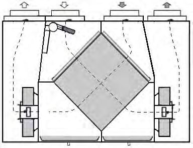
Simplified Installation (Return/Return Method)
Installation Notes
The ERV must be balanced.
Unit should be balanced on high speed with the furnace
blower on.
It is mandatory that the furnace blower run continuously
or ERV operation be interlocked with the furnace blower.
The duct configuration may change depending on the
ERV model.
A backdraft damper is recommended in the exhaust air
duct to prevent outdoor air from entering the unit.
The airflow must be confirmed on site using the
balancing procedures found in this guide.
Spring-Loaded Backdraft Damper (Recommended)
There is a location for an optional Backdraft Damper with the leaf hinge vertical. The damper is
installed on the “Stale Air to Outside Collar”
DIRECT CONNECTION of both the ERV SUPPLY AIR STREAM and
RETURN EXHAUST AIR STREAM to the FURNACE COLD AIR RETURN
AIR
40” (1 m) MINIMUM 3' min.
Dampers for balancing recommended
air flows, if not in collars of unit
Stale Air
to Outside
Fresh Air
from Outside
Forced Air
Furnace
Install backdraft damper
to ERV collar with leaf
hinge vertical
Attention/Warning
Weatherhood arrangement is for drawing purposes only. 6 ft (2 m) minimum separation is recommended, unless
dual hood is installed, also to be installed with 18 in (460 mm) above ground.
Check local codes/authority having jurisdiction for acceptance.
Backdraft dampers are recommended for the stale air to outside air duct. This damper prevents outdoor air from
entering the ERV during the operation of the furnace/air handler while the ERV is in standby, off, or recirculating.
4
Partially Dedicated System
Installation Notes
The ERV must be balanced.
Unit should be balanced on high speed with the furnace
blower on.
It is recommended that the furnace blower run
continuously or ERV operation be interlocked with the
furnace blower. Refer to building code.
The duct configuration may change depending on the
ERV model.
A backdraft damper is recommended in the exhaust air
duct to prevent outdoor air from entering the unit.
The airflow must be confirmed on site using the
balancing procedures found in this guide.
Spring-Loaded Backdraft Damper (Recommended)
There is a location for an optional Backdraft Damper with the leaf hinge vertical. The damper is
installed on the “Stale Air to Outside Collar”
DIRECT CONNECTION of the SUPPLY AIR STREAM to the FURNACE COLD AIR RETURN (Stale
air drawn from key areas of the home)
Exhaust Air from different
areas of the home RETURN
(bathrooms, kitchen) AIR
3' min.
Dampers for balancing air flows, recommended
if not in collars of unit
Stale Air to
Outside
Fresh Air
from Outside
Forced Air
Furnace
Install backdraft damper
to ERV collar with leaf
hinge vertical
Attention/Warning
Weatherhood arrangement is for drawing purposes only. 6 ft (2 m) minimum separation is recommended, unless
dual hood is installed, also to be installed with 18 in (460 mm) above ground.
Check local codes/authority having jurisdiction for acceptance.
Backdraft dampers are recommended for the stale air to outside air duct. This damper prevents outdoor air from
entering the ERV during the operation of the furnace/air handler while the ERV is in standby, off, or recirculating.
5
Fully Dedicated System
Installation Notes
The ERV must be balanced.
When balancing, all external exhaust systems should be
turned off (i.e. range hood, dryer exhaust, bathroom
vents).
All exhausting appliances should have their own make-up
air, as this is not an intended use of the ERV system.
The duct configuration may change depending on the ERV
model.
The airflow must be confirmed on site using the balancing
procedures found in this guide.
Spring-Loaded Backdraft Damper (Recommended)
There is a location for an optional Backdraft Damper with the leaf hinge vertical. The damper is
installed on the “Stale Air to Outside Collar”
Stale Air from various
areas of the home Fresh air to house -main
(bathrooms, kitchen) living areas, bedrooms,
livingroom, recreation
room, etc.
Dampers for balancing air flows,
if not in collars of unit
Stale Air to
Outside
Fresh Air
from Outside
Install backdraft damper
to ERV collar with leaf
hinge vertical
Attention
Weatherhood arrangement is for drawing purposes only. 6 ft (2 m) minimum separation is recommended, unless
dual hood is installed, also to be installed with 18 in (460 mm) above ground.
Check local codes/authority having jurisdiction for acceptance.
6Mounting the 30ERV
1. Begin by locating the four mounting tabs on the left
and right sides of the unit, at the front and back.
Four Mounting
2. Using a flat / pan head screwdriver, bend out the four Points
tabs to approximately 45o.
3. Once the tabs have been all bent outwards, insert
the "S" hooks through the four holes on the tabs.
4. Continue with mounting the ERV usign the
instructions found on page 8.
Mounting The 120ERV/120ERV-RX
It is important to isolate the (“L” Bracket) from Adjustable Height
the attached surface to minimize vibration. Use (“L” Bracket)
the hardware provided to attach the brackets.
Do not drill additional holes in the ERV.
7Hanging Straps - Installation Notes
Use 4 screws and 4 washers (not provided) to attach the hanging straps to the floor joists. The
washer must be wider than the eyelet of the grommet on the hanging strap. The hanging straps
are designed to reduce the possibility of noise, resonance and harmonics.
Step 1: Insert the screws and washers Step 3: Hook the bottom grommets of the
(not included) through the hanging strap straps through the “S” hooks. Pull down
grommets and fasten to the joists. vertically on the handle loops while lifting
Figure A the bottom of the unit. Figure B
Joist
Hanging Strap Grommets
Washers (not included) Buckles
Hand Loops
Screws (not included)
Note: Pull down on the
Buckles Hand Loops hand loops while lifting
Step 2: Unscrew the 4 machine screws located Step 4: Level the unit from right to left to right
on the upper side of the unit. Attach the “S” and front to back. Adjust the unit up by pulling
hooks and reinsert the machine screws. down vertically on the hand loops while lifting up
Figure C on the bottom of the cabinet.
Screws
Step 5: Fold the hand loops in excess strap
and secure with a nylon tie (not included).
Note: This illustration of
the unit may vary from the
diagram shown. “S” Hooks
Attention
Must push up on the bottom of the ERV when pulling the hanging straps.
8Grilles
Adjustable grilles should be used to balance the flow rates into and out of various rooms. The
grilles should not be adjusted after balancing the unit.
Grilles or diffusers should be positioned high on the wall or in the ceiling. Kitchen exhaust should
never be connected to the range hood. They should be installed at least 4 ft (1.2 m) horizontally
away from the stove.
Field supplied balancing dampers should be installed external to the unit to balance the amount
of stale air being exhausted with the amount of fresh air being brought into the house. Refer to
airflow balancing section.
The Lifebreath Kitchen Grille
(part# 99-10-002 6 in x 10 in)
Removable Filter
The Lifebreath Kitchen Grille includes a
removable grease filter. Most building codes
require that kitchen grilles are equipped
with washable filters.
The Lifebreath TechGrille
The TechGrille is a round, fully adjustable grille,
which provides quiet air distribution. Airflow
Supply
4 in (100 mm) Part # 99-EAG4
5 in (125 mm) Part # 99-EAG5
6 in (150 mm) Part # 99-EAG6
Airflow
8 in (200 mm) Part # 99-EAG8
Exhaust
9Grille Fittings
Quick Mount Fitting Stack Head Elbow (part # 99-WF4 / 99WF6)
(part # 99-QM6) Use this rough-in fitting before the drywall is installed. This
Use this rough-in fitting before the drywall is fitting is ideal for running ducting through 2 x 4 (min.)
Installed. studded walls.
Nail fitting onto the stud. Nail to stud.
Available size: 6 in. Available sizes are 4 in and 6 in.
Nail stack head
elbow onto stud
Connect to ERV ducting
2 x 4 Stud
Quick Mount 2 x 4 Stud
Fitting
TechGrille
1/2 in drywall
1/2 in drywall Stack Head
Nail or screw quick Elbow
mount fitting to stud
TechGrille
Connect to ERV ducting
Terminator Fitting (part # 99-TM 4/5/6)
Use this rough-in fitting before the drywall is installed. Suspended Ceiling Fitting (part # 99-CF6)
Nail or screw fitting onto the stud or joist. Use this fitting for ceiling tiles or finished/installed drywall.
Available sizes: 4 in, 5 in and 6 in. Cut a hole through the ceiling tile, insert the fitting and use the
retaining ring to hold the fitting in place.
Use this rough-in fitting before the drywall is installed.
For finished/installed drywall, use caulking around the lip if you do
Adapts to ridged and flex ducting not have access to attach the retaining ring.
Strong attachment for grilles, either vertically or horizontally Available size: 6 in.
Connect to ERV ducting
Connect to ERV ducting
Terminator
Fitting
Retaining ring
Ceiling
Fitting
Ceiling / wall Ceiling
drywall
Flush mount the lip of the
Nail / screw to
secure stud or ceiling fitting to ceiling
Flush mount the lip
joist
of the Terminator
fitting to the drywall TechGrille TechGrille
Caution
Do not mount exhaust grille within 4 ft (1.2 m) (horizontally) of a stove to prevent grease from entering the unit.
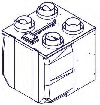
10Lifebreath Weatherhoods (Optional)
Fixed covered weatherhoods have a built-in bird screen with a 1/4 in (6 mm) mesh to prevent
foreign objects from entering the ductwork.
Installation Notes
The inner and outer liners of the flexible insulated duct must be clamped to the sleeve of the
weatherhoods (as close to the outside as possible) and the appropriate port on the ERV. It is very
important that the fresh air intake line be given special attention to make sure it is well sealed. A
good bead of high quality caulking (preferably acoustical sealant) will seal the inner flexible duct to
both the ERV port and the weatherhood prior to clamping.
The flexible insulated duct that connects the two outside weatherhoods to the ERV should be
stretched tightly and be as short as possible to minimize airflow restrictions.
Twisting or folding the duct will severely restrict airflow.
Hard (rigid) ducting which has been sealed and insulated should be used for runs over 10 ft
(3.3 m). Refer to your building code.
Collar is supplied to
Screen ensure vapor barrier is
(side view) 100% sealed to wall plate
1/4 in (6 mm)
Screen
12 in galvanized
pipe supplied
Exterior wall
Dual Hood Part 99-190
With the Lifebreath Dual Hood, only one 6 in hole is required in the exterior wall to complete two
connections: fresh air intake and stale air exhaust.
Attention/Caution
Contact your local building authority before installation of the Dual Hood to verify compliance with
local building codes.
Caution:
Weatherhood arrangement - requires a minimum of 6 ft (2 m) separation, a minimum of 18 in (460 mm) above the
ground, or above the depth of expected snow accumulation, and a minimum of 3 ft (1 m) from corner of building.
11Weatherhood Requirements
At least 6 ft (2 m) should separate the intake and exhaust hood, unless dual hood is installed.
At least 18 in (457 mm) above the ground, or above the depth of expected snow accumulation.
At least 3 ft (1 m) from the corner of the building.
Do not locate in garage, attic or crawl space.
Intake:
Should be located upstream (if there are prevailing winds) from the exhaust outlet.
At least 6 ft (2 m) away from dryer vents and furnace exhaust (medium or high efficiency
furnaces).
A minimum of at least 6 ft (2 m) from driveways, oil fill pipes, gas meters, or garbage containers.
Exhaust:
Not near a gas meter, electric meter or a walkway where fog or ice could create a hazard.
OUTSIDE CORNER INSIDE CORNER
3 ft (1 m) 3 ft (1 m)
recommended min. recommended min.
6 ft (2 m)
recommended min.
Unless Dual Hood
is installed
INTAKE EXHAUST
18 in (460 mm) min. 18 in (460 mm) min.
Attention/Caution
Contact your local building authority before installation of the Dual Hood to verify compliance with
local building codes.
Caution:
Weatherhood arrangement - requires a minimum of 6 ft (2 m) separation, a minimum of 18 in (460 mm) above the
ground, or above the depth of expected snow accumulation, and a minimum of 3 ft (1 m) from corner of building.
Sealant must be applied as per instructions or leakage and condensation may occur.
Insulate the Fresh Air Supply and Stale Air Exhaust duct work back to the unit.
12Main Control Installation
The Lifebreath Digital Control 99-DXPL02 is to be surface mounted onto a wall and the Lifebreath
Ventilation Control 99-BC04 may either be installed onto a flush mounted electrical switch box or
surface mounted onto a wall. Only one master control should be installed to a ventilation system (the
face plate on this illustration may not be exactly the same as yours).
Attention
Pay special attention not to damage the contact pins when removing and detaching the face plate (Figures B and C).
1. For DXPL02 control, remove the operating Operating Face Back
instructions card from the top of the control Instruction Plate Plate
Card
(Figure A).
2. Separate the face plate from the back plate by
firmly pulling apart (Figures B or C). Be careful
not to damage face plate contact pins.
3. For DXPL02 control, place the back plate of
the control in the desired location on the wall Keep top / bottom
and pencil mark the wall with the right and left Figure A Figure B vent openings clear
screw holes (Figure D).
Figure C Back (Two) 1/8 in holes for screws
4. For BC04 control, place the screws and Plate and anchors
anchors. back plate of the control in the Face
desired location on the wall and pencil mark Plate
the top and bottom screw holes.
(Figure E or F). 1.5" 1.5"
5. For mounting the control without a Decora
plate, break off top and bottom tabs and refer
to Figure F for mounting. Remove the back
plate from the wall and mark the center hole
for the wires in the middle of the screw holes.
Refer to Figure D, E or F for dimensions. 1 in hole for Wiring
wire opening.
Terminals
6. Drill (two) 1/8 in holes for the screws and wall Keep top / bottom
anchors (Figure D, E or F). For DXPL02 control, vent openings clear Figure D
drill a 1 in hole in the center (Figure D). For
BC04 control, cut in a 3/4 in by 1 in oval hole 1/8 in hole for Alternate Wall Mount
in the wall (Figure E or F). screw and
7. anchor 1/8 in hole for Break off tab
Pull 3 wire 20 gauge (min.) 100 ft length
screw and
(max.), through the opening in the wall. 1.625" anchor
8. Connect red, green, and yellow to the wiring 1 in x 3/4 in 0.75"
oval hole Wire hole
terminals located on the back plate (Figure D, E 1 in x 3/4 in
for wire 0.75" centered
oval hole between
or F). opening 1"
for wire screw
9. Attach the back plate to the wall using two opening 1"
holes
supplied screws and anchors. Wiring
Terminals 1.625"
Wiring
10. Attach the face plate to the back plate (Figure B 1/8 in
Terminals hole for
or C). Note: Be careful to correctly align the 1/8 in hole
for screw and screw and
face plate to avoid damaging the face plate anchor
anchor Break off tab
contact pins.
Figure E Figure F
11. For DXPL02 control, insert the operating
instructions card into the control (Figure A).
12. Connect the 3 wire 20 gauge (min.) 100 ft length (max.) to the terminal block located on ventilator (Red #3, Yellow #4
and Green #5). 13Selecting the Ventilation Rate That is Right for You
The modes of operation and speeds are used to adjust your indoor ventilation rate. Experiment with the
ventilation levels in your home to evaluate the ideal amount of ventilation to suit your home and
personal preferences. Operational modes available to you will depend on the main control that is installed.
Come features and modes may be unavailable to you.
I. Continuous Ventilation
This mode of operation provides continuous ventilation within the home. You may, for example, select
Continuous Ventilation at low speed for normal operation and increase to high speed during increased
activity levels, such as cooking and showering, etc.
II. 20 Minutes On, 40 Minutes Recirculation 20/hr 40/hr
This mode ventilates for 20 minutes and recirculates the household air every 40 minutes each hour. This
mode is not applicable if your ERV is connected to a forced air system.
III.20 Minutes On, 40 Minutes Standby 20/hr 40/hr
This mode of operation provides 20 minutes of ventilation each hour. You can use this ventilation mode at
low speed for low household activity levels or when the home is unoccupied.
IV. 10 Minutes On, 50 Minutes Standby 10/hr 50/hr
This mode of operation provides 10 minutes of ventilation each hour. You can use this ventilation mode at
low speed for low household activity levels or when the home is unoccupied. This mode is useful when
20/40 mode is providing too much ventilation.
V. Continuous Recirculation or
This mode continuously recirculates your household air (no ventilation). This mode is not applicable if your
ERV is connected to a forced air system.
VI. Continuous Low Fan Speed LO
This mode will operate the fan in low speed continuously at the selected operating mode (Ventilation or
Recirculation).
VII. Continuous High Fan Speed HI
This mode will operate the fan in high speed continuously at the selected operating mode (Ventilation or
Recirculation). This mode is useful when occupancy in the home or activity is high for an extended period
of time.
Recirculation
Recirculates existing household air without introducing fresh air. Recirculation modes (II and V) are not
applicable if your ERV is connected to a forced air system, since your forced air system already circulates the
household air. Recirculation modes are unavailable on some models.
Note
Due to ongoing research and product development, specifications, ratings, and dimensions are subject to change
without notice. Refer to www.LIFEBREATH.com for the latest product information.
Warning
Disconnect the power from the unit before cleaning or servicing.
To prevent electrical shock, it is extremely important to confirm the polarity of the power line that is switched by
the safety (disconnect) switch. The hot line (black) is the proper line for switching. Use either a voltmeter or test
lamp to confirm the absence of a voltage between the disconnect switch and ground (on the cabinet) while the
door is open. This procedure must be followed, as dwellings are occasionally wired improperly. Always ensure the
proper grounding of the unit.
14Installation and Operation of Wireless 20/40/60 Minute Timer: 99-DET02
The Timers may be installed onto a flush mounted electrical
switch box or it may be surface mounted onto a wall. Multiple
Timers may be installed in a ventilation system. To increase NOTE
the range of a wireless Timer, a RX02 Repeater should be used.
The wireless Timers and Repeaters must be matched to
Pairing: the main wall control of the HRV / ERV. This process is
1. Turn on the main wall control by pressing the ON/OFF called "Pairing". Multiple Timers and Repeaters can be
button and remove the battery from Timer. paired to a single wall control.
2. DET02 with DXPL02 Controls: Press the left and right
buttons simultaneously on the main wall control Figure A 1/8 in hole for
Back Plate
( and RESET buttons). The screen will go blank and the screw and
anchor
wireless symbol will appear flashing on the bottom right Face Plate
of the display. This indicates that the main control is now in
pairing mode. (Figure D)
3. DET02 with BC04 Control: Press the left and right
buttons simultaneously on the main wall control ( and
buttons). The bottom row of 3 LED's will begin flashing.
This indicates that the main control is now in pairing mode.
(Figure E)
4. Keep the Timer within 16” of the main wall control when
pairing. 1/8 in hole
for screw and
5. Install the battery in the DET02 Timer. All four lights on anchor
the Timer will immediately flash 5 times, then only the red
battery light will remain on for approximately 12 seconds Figure B
after which the "40" light flashes the rev code. 20, 40, 60
lights will flash until paired or will stop if not paired within Alternate Wall Mount Figure C
DXPL02
12 seconds. If pairing was not successful you now must Break off tab
1/8 in hole for Control
return to step 1 to restart the pairing process. screw and anchor
6. Press the button on the main wall control to exit pairing
mode when Timers have been successfully paired.
1/8 in
To pair additional DET02 Timers with the same wall control, or
hole for
if pairing was not successful, repeat steps 1-6. screw and
When paired, the DET02 Timers can be moved and installed anchor
elsewhere. Estimated range of the Timer is 40’ with no
obstructions. A RX02 Repeater may be installed to increase the Press Simultaneously
range of the Timers. to Initiate Pairing
Test if pairing was successful by pressing the Select Button and Break off tab Mode Figure D
listen for the HRV / ERV to initiate HIGH fan speed Ventilation.
Figure E Figure F
DET02 Timer
Un-pairing: BC04
1. Remove the battery from the back of the DET02 Timer Control Removable
Backplate
2. Press and hold the Select Button on the front of the Timer
NOTE: Your
3. While holding the Select Button, reinsert the battery in the control may look 20/40/60 Minute
Timer. Continue holding the select button until the LED different than the Status Lights
one shown.
under "40" begins flashing. The DET02 Timer will now be
Select Button initiates
unpaired with the main wall control. high speed ventilation
for 20, 40 or 60 min.
Installation:
Press Simultaneously Battery Indicator
1. Separate the face plate from the back plate by firmly
to Initiate Pairing Mode
pulling apart (Figure A).
2. For mounting the control without a Decora plate, break off top and bottom tabs and refer to Figure C for mounting.
3. Place the back plate of the control in the desired location on the wall and pencil mark the top and bottom screw holes
(Figure B or C). Drill two 1/8" holes.
4. Attach the back plate to the wall using the 2 supplied screws and anchors.
5. Attach the face plate to the back plate (Figure A).
15Installation and Pairing of Repeaters: 99-RX02
The RX02 Repeaters are to be plugged directly into a 120V power outlet
1. Turn on the main wall control by pressing the ON/OFF button .
2. RX02 with DXPL02 Controls: Press the left and right buttons simultaneously on the main wall
control ( and RESET buttons). The screen will go blank and the wireless symbol will appear
flashing on the bottom right of the display. This indicates that the main control is now in pairing
mode. RX02 with BC04 Control: Press the left and right buttons simultaneously on the main
wall control ( and buttons). The bottom row of 3 LED's will begin flashing. This indicates that
the main control is now in pairing mode.
3. The RX02 Repeater must be powered within 16” of the main wall control for pairing. If an outlet is
not available an extension cord should be used to power the repeater initially for pairing.
4. Plug the RX02 Repeater into the power outlet. The green light will flash after approximately 12
seconds indicating that the repeater is paired with the main wall control.
5. Press the ON/OFF button on the main wall control to exit pairing mode and the Repeater may
now be unplugged and moved to its permanent location.
To pair additional RX02 Repeaters with the same wall control, repeat steps
RX02
1-5 until all Repeaters have been paired.
Repeater
When installed in its permanent location, the green LED will remain solid to
indicate the best location and the Repeater can be moved farther if
required. The green LED will flash to indicate it is in a good location. A red Power
light indicates the Repeater is out of range and needs to be moved closer to Plug
the main wall control.
16Interlocking the ERV to an Air Handler or Furnace Blower
Connecting the ERV as illustrated will ensure the ERV Terminal Block
air handler/furnace blower motor is operating Wire
Connector
whenever the ERV is venting.
The ERV must be interlocked to the furnace/air
handler with a simplified installation (return/ Furnace
return installation). Thermostat
Furnace
Setting “Standby” When Using a Main Control
Terminal Strip
The ERV will be “fully-off” when the off position is selected
on the Main Control. Timers and/or other controls will not function when the ERV is in the off
position.The “fully-off” feature can be modified to “standby-off” by adding a jumper on the terminal
block between 2 (ON) and 3 (RED). “Standby” can also be achieved by setting the main control
to the ON position and selecting speed 0*. Timers and/or additional controls will initiate high speed
ventilation when activated.
*Speed 0 is not available on all controls.
Operating the ERV Without a Main Control and Adding Dry Contact Controls
A jumper must be in place between 2 (ON) and 3 (RED) on the terminal block to activate the ERV for
timers and/or dry contact controls.
Adding Dry Contact Controls
Low Speed: A jumper between 2 (ON) and 1 (LOW) initiates low speed ventilation.
High Speed: A jumper between 2 (ON) and 6 (HI) initiates high speed ventilation.
Dehumidistat: A dry contact for a dehumidistat is connected between 2 (ON) and 10 (BLK)
The ERV must have a jumper in place between 2 (ON) and 3 (RED) on the terminal block when
installing the unit without a main control.
Installer Selectable High Speed Settings
The circuit board on this unit has adjustable DIP switches for the selection of HIGH speed Hi1, Hi2
or Hi3. The factory setting is Hi3, which is the highest speed possible H2 will result in a lower
airflow than H3, with H2 the lower of the high speeds. Refer to the specification page found online
at; www.lifebreath.com for the airflow rates on Hi1, Hi2 and Hi3.
Note: Low speed is not adjustable.
Description Switch 1 Switch 2 Switch 3 Switch 4
Hi 3 (factory default) Factory Setting “ON” Leave on factory setting ON ON
Hi 2 Factory Setting “ON” Leave on factory setting OFF ON
Hi 1 Factory Setting “ON” Leave on factory setting ON OFF
Attention/Caution
Timers mount in standard electrical boxes.
Use 3 wire 20 gauge (min.) 100 ft length (max.) low voltage wire and multiple timers individually wired back to the unit.
Caution:
Consideration should be given to competing airflows when connecting the ERV in conjunction with an air handler/
furnace blower system.
Building codes in some areas require “fully-off” functionality. Check with your local building authority before
modifying the unit to “standby-off”. Unintentional operation of the ERV by the end user may occur if the unit is
modified from “fully-off” to “standby-off”.
17Installation and Operation 20/40/60 Minute Timer: 99-DET01
Operating your Lifebreath 20/40/60 Minute Fan Timer
Press and release the Select Button to activate a 20, 40 or 60 minute high Status
Yellow
speed override cycle. The Light will illuminate and the unit will run on Lights
Red
high speed ventilation for the selected time. The Light will dim after 10 Green
sec. for run time. The Light will flash during the last 5 min. of the cycle.
All timers connected to the unit will illuminate for the duration of the Select Button
override when the Select Button is pressed. initiates high
speed ventilation
Lockout Mode for 20, 40 0r 60 min.
Lockout Mode is useful if you wish to disable the timers.
The timer can be set to lockout mode by pressing and holding the Select
Button for five seconds. After 5 sec., the Light will flash; release the Se-
lect Button. The timer is now in lockout mode. If the Select Button is Red #3
Yellow #4
pressed during lockout mode the Light will momentarily illuminate but no
Green #5
override will be initiated.
If lockout mode is initiated when the timer is activated, the timer will
continue its timed sequence but will not allow any further overrides to be
initiated. Lockout mode can be unlocked by pressing and holding the Select
Button for 5 sec. After 5 sec. the Light will stop flashing. Release the Select
Button and the timer will now operate normally.
Plug Installation - 130ERV/130ERVR
The plugs are located in the ERV manual bag. The plugs will be installed into the 2 holes
located in the bottom tray of the ERV. They must be inserted from the inside of the unit to
ensure the holes are fully sealed, see detail below.
Core
Plug Plug
Foam Tray Pre-punch hole Pre-punch hole Foam Tray
Note
Ensure the plugs are firmly seated within the foam tray before operation.
18Dimensional Drawing for 130ERV/130ERVR Models
Stale Fresh Stale Fresh
Air To Air From Air From Air To
Outside Outside Inside Inside Note: Front clearance of 25 in (635 mm)
is recommended for servicing unit. All
Recirculating ducts use 5 in (125 mm) oval collars,
Damper balancing dampers are located on all
(For 130ERVR collars.
Model Only)
17 1/4 in (438 mm)
Filter
14 in (356 mm)
Core
Motorized
Impeller 22 3/4 in (578 mm)
Front View Top View
Dimensional Drawing for Models 120ERV and (120ERVRX - in brackets)
16 1/2 in (419 mm) Core Balancing Damper Note: Bottom clearance of
25 in (635 mm) is
Fresh Air Fresh Air
recommended for servicing
From Outside To Inside
18 1/4 in (464 mm)
(Stale Air unit. All ducts use 5 in
(Stale Air (125 mm) connections.
From Inside) To Outside)
Stale Air Stale Air
From Inside To Outside
(Fresh Air (Fresh Air
From Outside) To Inside)
Bottom View
9 1/4 in (235 mm)
28 5/8 in (727 mm) Side View
19Dimensional Drawing for 230ERV/230ERVR Models
Stale Fresh Stale Fresh
Air To Air From Air From Air To
Note: Front clearance of 25 in (635 mm) is
Recirculating Outside Outside Inside Inside
recommended for servicing unit. All ducts use
Damper
6 in (152 mm) round collars, balancing
(For 230ERVR
Model Only) dampers are located on two collars.
19 in (483 mm)
Filter
14 3/4 in (375 mm)
Core
Motorized
Impeller
33 5/8 in (850 mm)
Balancing
FRONT VIEW TOP VIEW Dampers
Dimensional Drawing for 30ERV Model
Fresh Air
Fresh Air Note: Front clearance of 25 in (635 mm) is
To Inside
To Outside recommended for servicing unit. All ducts
use 4 in (102 mm) round collars, balancing
dampers are located in each air stream.
18 3/4" (476 mm)
19 1/4" (489 mm)
Stale Air 17 7/8" (454 mm)
From Inside Fresh Air
From Outside
Front View
Top View
20Balancing the Airflows
Balancing the airflows is critical to ensuring that the amount of air introduced from the outside of
the building equals the amount of air exhausted to the outside of the building. If these two airflows
are not properly balanced, the following issues may occur:
A positive or negative pressure in the house
ERV not operate at its maximum efficiency
The unit not defrost properly
Airflow Measuring Gauge
A digital manometer is a suitable instrument for the balancing of ��
��
airflows.
99-BAL-KIT Airflow Balancing Kit
Kit includes a digital manometer, pitot tube, hose and tool bag. Figure A
DICITAL IANDIETER
Digital Manometer
Gauge Attachments
When sampling an airflow, various attachments are available DUCT
for use on a digital manometer. Consult with your Lifebreath
AIR
distributor for available options such as a pitot tube, flow FLOW
measuring station, and an airflow measuring probe.
Pitot tube
Figure B illustrates a digital manometer with a pitot tube
attachment. This combination will measure the system air Digital
velocity pressure accurately, regardless of the duct size or manometer
shape (either round or rectangular).
Figure B
Digital manometer with a
pitot tube attachment
Attention
Continuous, excessive, positive pressure may drive moist indoor air into the external walls of the building. Once
inside the external walls, moist air may condense (in cold weather) and degrade structural components or cause
locks to freeze.
Continuous, excessive, negative pressure may have several undesirable effects. In some geographic locations, soil
gases such as methane and radon gas may be drawn into the home through basement or ground contact areas,
and may also cause the backdrafting of vented combustion equipment.
21Determining the CFM
After balancing the airflows, calculate the CFM flow rate.
Example
This example shows how to determine the airflow for a 6 in
diameter duct. If the duct velocity pressure reads 0.025 in w.g.
on the digital manometer, use the chart that came with the pitot
tube to determine a duct velocity of 640 ft/min. for a duct velocity
pressure of 0.025 in w.g.
CFM Calculation Cross section area of some common duct
CFM = feet per minute x cross section area of duct sizes:
0.087 for 4 in duct 0.139 for 5 in duct
= 640 x 0.196
0.196 for 6 in duct 0.267 for 7 in duct
= 125
Units with Balancing Collars
Install these units with the dampers fully open and damper down the duct with the higher airflow
to equal the lower airflow. Refer to the “Balancing the Airflows” page found in this manual.
All other units require dampers for balancing airflows installed into the “Fresh Air to Building” and
“Stale Air from Building” ductwork.
When connecting ductwork to
the collar, take note where
Push and turn with slotted screws are located. Screws
screwdriver. Damper should be located no further
automatically locks when than 1/2 in from outside edge of
pressure is released. collar, so as not to impede
operation of the damper.
1/2 in
Hard/Rigid Ducting Insulated flexible ducting
Attention
Installations where the ERV is ducted directly to the return of a furnace may require additional dampening on the
fresh air to building duct. This is due to the high return static pressures found in some furnace installations.
22Balancing Preparation
Prior to performing the air balancing procedure, perform the following steps:
Seal the ductwork.
Confirm the installation and proper operation of all the components of the ERV.
Fully open the balancing dampers.
Turn off all household exhaust devices (range hood, clothes dryer, bathroom fans).
Set the ERV at high speed.
Prior to balancing the unit, first adjust airflows in the branch lines to specific areas of the house.
o o
If the outdoor temperature is below 0 C (32 F), ensure the unit is not running in defrost.
If the system is a simplified or partially dedicated installation, operate the furnace/air handler at
high speed.
Balancing the Airflow With a Pitot Tube
Stale Air from Building
Pitot tube tip facing
Balancing Drill 3/16 in holes in towards the air stream
Damper Stale & Fresh air
ducts.
Fresh Air to Building
Balancing Damper
Step 2: Insert the pitot tube with the tip facing towards the air
Step 1: Drill a 3/16 in hole in the duct, ideally 3 stream in the stale air from Building air stream. Move the pitot
ft downstream and 1 ft upstream of any elbows tube around in the duct (facing toward the airflow) and take an
or bends in the fresh air and stale air streams. average reading. Record the reading.
Balancing
Damper
Seal holes.
Pitot tube tip facing
towards the air stream.
Balancing Damper
Step 4(a): Review the readings and damper down the duct with
the highest duct velocity pressure. Repeat step 2 and step 3 until
both ducts show identical readings.
Step 3: Repeat step 2 Step 4(b): Upon completion of balancing, seal the holes (foil tape
to measure the fresh air to building duct. recommended).
23Troubleshooting
SYMPTOM CAUSE SOLUTION
Poor Airflows • 1/4” (6 mm) mesh on the outside hoods is plugged • clean exterior hoods or vents
• filters plugged • remove and clean filter
• core obstructed • remove and clean core
• house grilles closed or blocked • check and open grilles
• dampers are closed if installed • open and adjust dampers
• poor power supply at site • have electrician check supply voltage at house
• ductwork is restricting ERV • check duct installation
• improper speed control setting • increase the speed of the ERV
• ERV airflow improperly balanced • have contractor balance ERV
Supply air feels cold • poor location of supply grilles, the airflow may • locate the grilles high on the walls or under the baseboards,
irritate the occupant install ceiling mounted diffuser or grilles so as not to directly
spill the supply air on the occupant (eg. over a sofa)
• outdoor temperature extremely cold • turn down the ERV supply speed. A small duct heater
(1kW) could be used to temper the supply air
• placement of furniture or closed doors is restricting the
movement of air in the home
• if supply air is ducted into furnace return, the furnace fan
may need to run continuously to distribute
ventilation air comfortably
Dehumidistat is not Operating • outdoor temperature is above 15°C (59°F) • dehumidistat is functioning normally (see Auto Dehumidistat
Disable in this manual)
• improper low voltage connection • check that the correct terminals have been used
• external low voltage is shortened out by a staple or nail • check external wiring for a short
• check dehumidistat setting, it may be on OFF • set the dehumidistat at the desired setting
Humidity Levels are too High Condensation • dehumidistat is set too high • set dehumidistat lower
is appearing on the windows • avoid hanging clothes to dry, storing wood and venting clothes
• lifestyle of the occupants dryer inside. Heating wood may have to be moved outside
• vent crawl space and place a vapor barrier on the floor
• moisture coming into the home from an unvented of the crawl space
or unheated crawl space • ducts from the washroom should be sized to remove moist
• moisture is remaining in the washroom and kitchen areas air as effectively as possible, use of a bathroom fan for
short periods will remove additional moisture
• on humid days, as the seasons change, some condensation
• condensation seems to form in the spring and fall may appear but the homes air quality will remain high
with some ERV use
• ERV is set at too low a speed • increase speed of the ERV
Humidity Levels are too Low • dehumidistat control set too low • set dehumidistat higher
• blower speed of ERV is too high • decrease ERV blower speed
• lifestyle of occupants • humidity may have to be added through the use of humidifiers
• ERV airflows may be improperly balanced • have a contractor balance ERV airflows
ERV and / or Ducts Frosting up • ERV airflows are improperly balanced • Note: minimal frost build-up is expected on cores before
• malfunction of the ERV frost prevention system unit initiates defrost cycle functions
• have HVAC contractor balance the ERV
• ensure damper defrost is operating during self-test
Condensation or Ice Build Up in Insulated • incomplete vapor barrier around insulated duct • tape and seal all joints
Duct to the Outside • a hole or tear in outer duct covering • tape any holes or tears made in the outer duct covering
• ensure that the vapor barrier is completely sealed
Excessive vibration Dirt on fan wheels Have a contractor service ERV
24Dépannage
SYMPTÔME CAUSE SOLUTION
Débit d'air médiocre le treillis de 1/4 po (6 mm) sur les nettoyez les évents ou capuchons extérieurs
capuchons extérieurs est bouché retirez et nettoyez le filtre
filtres bouchés retirez et nettoyez le noyau
noyau obstrué vérifiez et ouvrez les grilles
grilles dans la maison fermées ou ouvrez et ajustez les registres
bloquées demandez à un électricien de vérifier l'alimentation électrique
les registres, s'ils ont été posés, sont vérifiez la pose des conduits
fermés augmentez l'allure du VRE
mauvaise alimentation électrique sur les faites équilibrer le VRE par un entrepreneur
lieux
les canalisations restreignent le débit d'air
commande de vitesse mal réglée
débit d'air du VRE mal équilibré
L'air qui arrive grilles d'admission mal placées; la placez les grillages à une bonne hauteur sur les murs ou bien
semble froid circulation d'air pourrait irriter les sous les plinthes; posez un diffuseur ou des grilles dans le
occupants plafond, de manière à ne pas diriger l'air vers les occupants
température extérieure extrêmement (comme par-dessus un sofa)
froide ralentissez l'admission du VRE; vous pourriez utiliser un petit
chauffe-conduit (1 kW) pour tempérer l'air admis
des meubles mal placés ou des portes fermées empêchent l'air
de circuler librement
si l'air fourni est acheminé dans la chambre de retour de la
fournaise, il se pourrait que son ventilateur doive tourner sans
arrêt, afin de répartir confortablement l'air de ventilation
Le déshumidistat ne température extérieure au-dessus de le déshumidistat fonctionne normalement (voyez la section sur
fonctionne pas 15ºC (59ºF) la désactivation du déshumidistat dans le manuel)
mauvaise connexion de basse tension assurez-vous qu'on a utilisé les bonnes bornes
la basse tension extérieure est il pourrait y avoir un court-circuit dans le câblage externe
court-circuitée par un crampon ou un réglez le déshumidistat au niveau désiré
clou
vérifiez le réglage du déshumidistat, car il
pourrait avoir été réglé à OFF
Niveau d'humidité réglage trop haut du déshumidistat réglez le déshumidistat plus bas
trop élevé; VRE pas assez puissant pour un "hot évitez d'étendre du linge à sécher, d'emmagasiner du bois et de
condensation sur les tub", une piscine intérieure, etc. ventiler la sécheuse à linge à l'intérieur; vous devrez
fenêtres mode de vie des occupants peut-être sortir le bois de chauffage dehors
humidité qui pénètre dans la maison en aérez l'espace sanitaire et mettez un pare-vapeur sur le
provenance d'un espace sanitaire non plancher de cet espace sanitaire
ventilé ou non chauffé les conduites provenant de la salle de bain devraient être assez
l'humidité reste dans la salle de bain et la grosses pour retirer l'air humide aussi efficacement que
cuisine possible; en faisant marcher le ventilateur de la salle de bain
il semble y avoir de la condensation au pendant de courtes périodes, vous ferez disparaître encore plus
printemps et à l'automne d'humidité
la vitesse prévue pour le VRE est trop par temps humide, lorsque les saisons changent, il pourrait y
basse avoir un peu de condensation, mais la qualité de l'air dans la
maison demeure excellente quand on utilise le VRE
augmentez la vitesse du VRE
Degré d'humidité déshumidistat réglé trop bas réglez le déshumidistat plus haut
trop bas trop grande vitesse de la soufflante du faites ralentir la soufflante du VRE
VRE vous devrez peut-être employer des humidificateurs
mode de vie des occupants faites équilibrer la circulation d'air du VRE par un entrepreneur
débits d'air du VRE mal équilibrés
Formation de givre débits d'air du VRE mal équilibrés N.B. : il faut s'attendre à une légère accumulation de givre sur
dans le VRE et/ou Mauvais fonctionnement du système le noyau, avant le déclenchement du cycle de dégivrage
les conduites demandez à un entrepreneur spécialisé d'équilibrer le VRE
de prévention du gel du VRE
assurez-vous que le dégivrage par registre fonctionne durant
l'auto-vérification
Trop d'eau dans le bacs de drainage bouchés voyez s'il y a des obstructions dans la canalisation
fond du VRE mauvais raccordement aux d'écoulement
canalisations d'écoulement du VRE les tubes pourraient être tortillés
le VRE n'est pas de niveau
canalisations d'écoulement obstruées
noyau échangeur du VRE mal installé
24Préparatifs pour l'équilibrage
Avant de procéder à l'équilibrage, n'oubliez pas de vérifier les points suivants :
• Tout le réseau de conduits doit avoir été complètement scellé.
• Tous les composants du VRE doivent être en place et en bon état de marche.
• Les registres d'équilibrage doivent être complètements ouverts.
• Tous les dispositifs d'évacuation (hotte de cuisinière, sécheuse, évents de salles de bains)
doivent être arrêtés.
• Le VRE doit être réglé à sa haute vitesse.
• Avant d'équilibrer l'appareil, les débits d'air dans les canalisations secondaires devraient être
ajustés.
• Si la température extérieure est au-dessous de 0ºC (32ºF), il faut s'assurer que l'appareil ne
fonctionne pas à son mode de dégivrage.
• S'il s'agit d'une installation simplifiée ou partiellement spécifique, faites fonctionner la fournaise
ou l'appareil de traitement de l'air à haute vitesse.
Équilibrage des débits d'air avec un tube de Pitot
Air vicié de l'intérieur
Registre Percez un trou de L'extrémité du tube de
d'équilibrage 3/16 po dans les Pitot doit faire face au
conduits d'air vicié et flux d'air.
d'air neuf
Air neuf vers l'intérieur
Registre d'équilibrage
Étape 2 : Introduisez le tube de Pitot dans le conduit d'air vicié
Étape 1 : Percez un trou de 3/16 po dans le
de l'intérieur, en dirigeant son extrémité vers le flux d'air vicié.
conduit, idéalement 3 pieds en aval et 1 pied en
Déplacez le tube de Pitot dans le conduit (toujours en faisant face
amont des coudes ou changements de direction
au flux d'air) pour prendre une lecture moyenne ou typique.
dans les circuits d'air neuf et d'air vicié.
Registre
d'équilibrage Bouchez les
L'extrémité du tube de Pitot trous.
doit faire face au flux d'air.
Registre d'équilibrage
Étape 4(a) : Vérifiez les lectures et servez-vous du registre
pour réduire le débit du conduit où la vélocité est la plus haute.
Répétez les étapes 2 et 3 jusqu'à ce que vous obteniez des
lectures identiques dans les deux conduits.
Étape 4(b) : Une fois l'équilibrage terminé, scellez les trous
Étape 3 : Répétez l'étape 2 pour mesurer le débit
(de préférence avec un ruban adhésif métallique).
dans le conduit de l'air neuf vers l'intérieur.
23Comment déterminer le débit d'air en pcm
Après avoir achevé l'équilibrage, calculez le débit d'air en pieds cubes/
minute.
Exemple
Voici un exemple dans lequel on détermine le débit d'air dans un conduit
de 6 pouces. Servez-vous du tableau fourni avec le tube de Pitot pour
déterminer une vélocité dans le conduit de 640 pieds/minute pour une
pression due à la vitesse de 0.025 po (colonne d'eau).
Calcul des pieds cubes/minute (pcm) Surface transversale de quelques
pcm = pieds par minute x surface transversale du conduit conduits ronds souvent utilisés :
0.087 pour un conduit de 4 po
= 640 x 0.196
0.139 pour un conduit de 5 po
= 125 0.196 pour un conduit de 6 po
0.267 pour un conduit de 7 po
Appareils munis de colliers d'équilibrage
Installez ces appareils avec les registres complètement ouverts, puis réduisez le débit dans la
canalisation qui a le plus grand débit d'air pour qu'il soit égal au plus faible débit. Consultez les
méthodes d'équilibrage des débits d'air qui sont proposées dans ce manuel. Tous les autres
appareils exigent des registres pour équilibrer les débits d'air et on les pose dans les canalisations
“Air neuf vers l'intérieur” et “Air vicié de l'intérieur”.
Lorsque vous raccordez la
canalisation au collier, prenez
Poussez et tournez avec note de l'emplacement des vis.
un tournevis à lame plate. Ces vis devraient être placées
Le registre se bloque pas plus loin que 1/2 po du
automatiquement lorsqu'on bord extérieur du collier, afin de
relâche la pression. ne pas entraver le déplacement
du registre.
1/2 po
Gaine dure/rigide Gaine flexible isolée
Attention
• Les installations où le VRE est raccordé directement à la reprise d'une fournaise pourraient exiger un amortissement
additionnel sur la canalisation qui achemine l'air neuf dans l'édifice. Cette précaution est parfois nécessaire à cause
de la haute pression statique de retour que produisent certaines fournaises.
22You can also read