MEMORY ALLOY WHEELS FOR MARS ROVERS - Giovanni Zambelli Arsequell BACHELOR'S THESIS
←
→
Page content transcription
If your browser does not render page correctly, please read the page content below
RESEARCH OF SHAPE
MEMORY ALLOY WHEELS FOR
MARS ROVERS

Giovanni Zambelli Arsequell

BACHELOR’S THESIS
May 2021

Mechanical Engineering
ABSTRACT

Tampereen ammattikorkeakoulu / Tampere University of Applied Sciences
Universitat Politècnica de Catalunya / Polytechnic University of Catalonia
Mechanical Engineering

GIOVANNI ZAMBELLI ARSEQUELL:
Research of shape memory alloy wheels for Mars rovers

Bachelor's thesis 60 pages
May 2021

The degradation of Curiosity’s wheels has stated that new technologies need to
be used for solving the problem of wheel wear on Mars exploration. One of these
technologies is invented by NASA and consists in the usage of Shape Memory
Alloys (SMA) to build a flexible deformable wheel that show no permanent
damage after deformation.

This thesis is the investigation of how Shape Memory Alloys work to understand
its usage in exploration rover wheels, in particular for Mars rovers.

The thesis starts with an investigation to understand how wheels of rovers were
made in the past, how they are done nowadays and how are they going to be in
the next years. Leading to a deep research on Shape Memory Alloys, going
through the material itself and its properties, explaining how it works and how the
structure of the wheel developed by NASA works.

The research provides a background on rover wheels, that lead to the
understanding of Shape Memory Alloys and their usage on wheels for Mars
exploration rovers.

Key words: shape memory alloy, rover
It’s human nature to stretch, to go, to see, to understand.
 Exploration is not a choice, really; it’s an imperative.

 Michael Collins | Astronaut | Gemini 10 | Apollo 11
CONTENTS
Preface ............................................................................................................... 1

List of Symbols.................................................................................................... 4

List of Figures ..................................................................................................... 5

Acknowledgements ............................................................................................. 6

PART I INTRODUCTION ................................................................................ 7

1. Introduction ..................................................................................................... 8

1.2 Objectives ..................................................................................................... 8

PART II BACKGROUND ................................................................................ 9

2.1 About Mars .............................................................................................. 10

2.2 The wheels of a Rover ............................................................................ 14

 2.2.1 The Lunokhod 1................................................................................ 16

 2.2.2 MET-ROVER .................................................................................... 18

 2.2.3 Lunar Roving Vehicle ....................................................................... 19

 2.2.4 Sojourner .......................................................................................... 21

 2.2.5 Mars Exploration Rovers .................................................................. 22

 2.2.6 Curiosity............................................................................................ 23

 2.2.7 Wheel degradation on Curiosity’s wheels ......................................... 26

 2.2.8 Perseverance ................................................................................... 27

 2.2.9 ExoMars 2022 .................................................................................. 28

2.3 Flexible wheels and their interaction with different soil conditions .......... 30

2.4 Summary ................................................................................................. 33

PART III SHAPE MEMORY ALLOY WHEEL ............................................... 34

3.1 Concept ................................................................................................... 35

3.2 Material ................................................................................................... 38

 3.2.1 Properties ......................................................................................... 38

3.3 Structure ................................................................................................. 43
PART IV CONCLUSIONS ............................................................................ 49

4.1 Conclusion .............................................................................................. 50

 4.1.2 Future steps...................................................................................... 51

Bibliography ...................................................................................................... 52
3

Preface
Before starting with the thesis itself I would like to share my thoughts on how this
work started and how it led to the present thesis. I have always been amazed by
space technologies, even though my bachelor’s degree is not oriented in space,
everyone can focus his own work on what he thinks is more interesting, for me,
my focus has always been on space. Following the end of my 3 rd year on the
university, I started thinking about what I was going to do on my bachelor’s thesis
as it was the first project that I could decide what I could do and almost completely
do it by my own, so I had to pick a subject of interest. On that time, I saw a
documentary of the Curiosity and started thinking about Curiosity’s wheels
damage and how the wheels work nowadays, that led me to investigate on why
are the wheels rigid and this small research led me to know the existence of a
new technology that NASA has been developing for the last years, as I wanted
to know more I decided to do it as my bachelor’s thesis. Even though I am not a
material science student, I think the work done in this paper was useful for me as
it let me to know more about this new technology and can help others to get
inspired, and possibly follow my work to make an implementation of the wheel.

It also made me to improve as a human being as I did this thesis while doing an
international mobility program in Tampere, being out of home, getting to know
people from different part of the world that share the same passion than me made
me realize how important is to work together regardless of where are people from,
and working as a group is essential on achieving great challenges and goals.
4 List of Symbols Weight S seconds P Pressure A Area D Diameter Frictional force ( ) Constant of friction Base Length Deflection factor Rate of deformation Martensite start temperature Martensite finish temperature Austenite start temperature Austenite finish temperature Martensite deformation temperature
5

List of Figures
Figure 1. Diagram of a wheel ............................................................................ 10
Figure 2. Mars dust storm ................................................................................. 12
Figure 3. 'Ireson Hill' ......................................................................................... 13
Figure 4. 'Vera Rubin Ridge' ............................................................................. 13
Figure 5. Gale Crater. ....................................................................................... 13
Figure 6. Dust devil tracks on Mars. .................................................................. 14
Figure 7. Lunokhod 1 ........................................................................................ 17
Figure 8. Lunokhod-1 self-propelled chassis .................................................... 18
Figure 9. MET ................................................................................................... 19
Figure 10. Lunar Roving Vehicle ....................................................................... 20
Figure 11. Lunar Roving Vehicle wheels ........................................................... 20
Figure 12. Sojourner ......................................................................................... 21
Figure 13. Rocker-Bogie ................................................................................... 21
Figure 14. MER ................................................................................................. 22
Figure 15. JPL Rovers ...................................................................................... 24
Figure 16. EDL .................................................................................................. 25
Figure 17. Diagram of the Curiosity's wheel. ..................................................... 26
Figure 18. Curiosity’s wheels punctures. (Credit: NASA) .................................. 27
Figure 19. Wheel comparison ........................................................................... 28
Figure 20. ExoMars........................................................................................... 29
Figure 21. The ExoMars wheels. ...................................................................... 30
Figure 22. Wheel interaction. ............................................................................ 31
Figure 23. MST ................................................................................................. 36
Figure 24. Shape Memory Alloy wheel tire ....................................................... 37
Figure 25. Hysteresis loop ................................................................................ 39
Figure 26. Nitinol Schematic ............................................................................. 40
Figure 27. Nitinol behaviour. ............................................................................. 41
Figure 28. Martensitic transformation temperature ........................................... 42
Figure 29. Stress-strain curves ......................................................................... 43
Figure 30. Superelastic sprin structure. ............................................................ 45
Figure 31. Toroidal shape of SMA tire. ............................................................. 46
Figure 32. Forces on the wheel......................................................................... 46
Figure 33. Radially stiffened SMA ..................................................................... 47
6

Acknowledgements
First, I would like to thank several people for helping me through the process of
making this thesis and my bachelor’s degree.

I would like to thank my university, the Univeristat Politècnica de Catalunya for
teaching me the values of work, and the basics of engineering, so I can become
an exceptional engineer in the future.

I would also like to thank my thesis supervisor Antti Perttula for guiding me
through my thesis.

And last but not least I would like to thank my family for supporting me my whole
life and my friends for being there always that I needed it.
7

 Part I

INTRODUCTION
8

1. Introduction

Space technology is evolving every day and new challenges appear as we
advance on our aim to discover new worlds. Mars has been since many years
our focus on space exploration, right now we do not have yet the technology to
send humans to Mars, even though we will soon, we are now in a phase where
we send different spacecrafts to explore the planet for us, between these there
are the rovers, and rovers play an important role on this exploration phase as
they are able to move through Mars surface while making science missions.

Many generations of rovers have been sent to Mars, and as we persevere in our
technology, we try to go further and achieve bigger goals. This thesis is the
investigation and research of one of the new technologies Mars rovers could use
in the future, not only on Mars but also on the Moon and even on Earth, although
the thesis is mainly focused on Mars applications.

Since NASA’s Curiosity rover started having problems with the wheels, the
wheels have been in the spotlight of engineers to try to avoid damage and find
solutions to it. NASA has developed a new concept of wheel; it uses shape
memory alloys to build a flexible wheel that can adapt to the surface recovering
its original shape, without permanent damage.

The purpose of this thesis is to do a proper research of exploration rovers, to
understand how this new technology works, to question its viability on Mars
environment, to find problems of this innovation and to lead this research to new
ideas that could improve this technology.

1.2 Objectives
The main objectives and goals of this thesis are described below:

 • To understand the functionality of the wheel for planetary exploration
 applications, in specific for Mars.
 • To document the technology.
 • To discover new technologies.
 • To try to find possible implementations.
9

 Part II

BACKGROUND
10 Mars is not quite like Earth, in fact, is a very threatening place for humans, it is cold, windy, dusty, and even has a toxic atmosphere for us. Mars is the nearest and most habitable planet in our solar system, even with all the extreme conditions that it has, live could possibly be sustained, that is why is so interesting for us. Since the 1960s, Mars has been in the spotlight of space companies and in the 1965, the Mariner 4 successfully reached Mars being the first mission to reach the red planet, it sent 21 photos, the first photos of another planet from space. Since then, we have aimed to go there and study more the Red Planet. 2.1 About Mars Mars is smaller than Earth, its radius is half of Earth’s radius, and its mass is less than one tenth of the mass of Earth. So, gravity on Mars is quite weak compared to our planet, due to the less amount of mass, the average gravity acceleration is 3.72076 ⁄ 2 , about 38% of that on Earth, that means that everything that we carry to Mars will have less gravitational force than on Earth. This is an important point because the rover will weigh less than normally would do here. Let’s put a simplification example: Figure 1. Force diagram of a wheel We see here a simplified diagram of the forces that a wheel must suffer, is the gravitational force that pulls the mass of the wheel to the ground, on Mars, the value of is way lower than on Earth. That directly affects the frictional force that is necessary for the wheel to spin, see that is equal or lower than the constant of friction ( ) multiplied for the N force (same value than ) so if
11

is lower, so it is . Meaning that it will be harder to provide traction as the rover
will weigh less. This also affects the testing of the Rover’s wheels on Earth, gravity
it is not something we can change obviously, so a clever way to test prototypes
is to make a similar model that would weigh the same on Mars (reducing its
mass).

Mars atmosphere is about 100 times thinner than Earth, that means it has way
less pressure; about 6 millibars (Earth's atmospheric pressure at sea level is
approximately 1013 millibars).

Its composition is made of:

 • Carbon dioxide ( 2): 95.32%
 • Nitrogen ( 2 ): 2.7%
 • Argon ( ): 1.6%
 • Oxygen ( 2 ): 0.13%
 • Carbon monoxide ( ): 0.08%
 • Also in minor amount (ppm) there is: Water ( 2 ) - 210; Nitrogen Oxide
 (NO) - 100; Neon (Ne) - 2.5; Hydrogen-Deuterium-Oxygen (HDO) - 0.85;
 Krypton (Kr) - 0.3; Xenon (Xe) - 0.08

Corrosion is also an important aspect to consider on Mars, in fact, corrosion
resistance is one of the most important properties in selecting materials for
surface operations spacecrafts. Currently the materials are selected assuming
that the corrosion on Mars is the same as that on Earth. But the discovery of liquid
brines on the surface of Mars led to several investigations to know if corrosion
was a cause on the Curiosity rover wheels as the components of the Martian
environment that could cause corrosion on metals include: the atmosphere, soil
composition and chemistry, the radiation and the liquid brines [1]. More studies
are needed to understand the interaction between materials and the Martian
environment, so it is still not clear if corrosion can be a problem for metallic
compound on Mars.

Mars also has an interesting surface.

Its surface it is made primarily of magmatic rocks, also from sedimentary and
metamorphic rocks. These rocks consist predominantly of minerals that
crystallize from magma. But we can find a lot of different terrains on mars; rocky
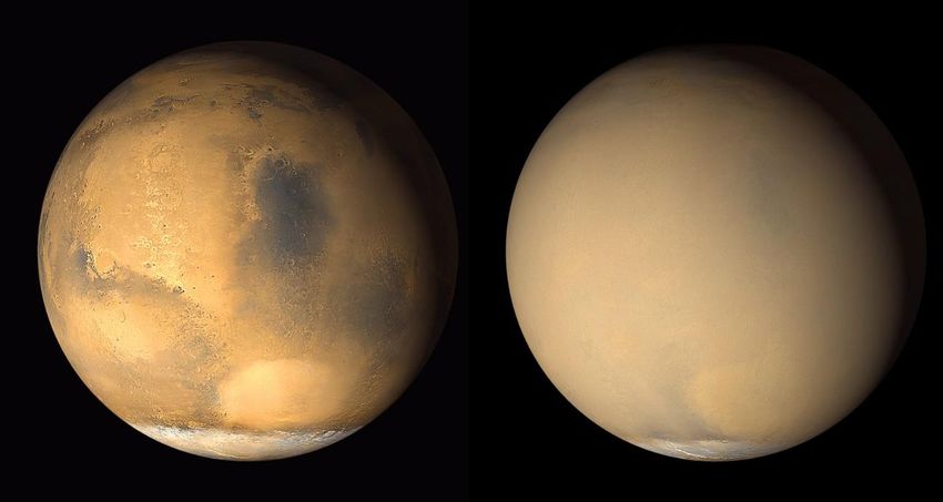
12

sites, sand dunes, craters, volcanic locations, etc. and they all can be shrouded
by a single sandstorm, covering it all with windblown dust.

Wind on mars redistribute surface material, these winds are not usually very fast
(only some kilometers per hour), but Mars is capable of windstorms that can strip
the surface of some dust and uncover rocks. Rovers found that the atmosphere
gets turbulent on each sunny afternoon as heat rise from the surface. This
turbulence generated the famous “dust devils” and they play an important role in
lifting the fine dust into the atmosphere, exposing what was hided beneath the
dust.

In Figure 2 we can see how Mars can change because a dust storm.

Figure 2. Mars before a dust storm in June (on the left) and after a global dust storm in July (on the right).
Picture taken by Mars Global Surveyor

A Mars rover needs to be able to climb any type of terrain that can be found on
the designated mission site. From sand dunes to solid rocky hills.

To show how different surfaces and landscapes can be on Mars, below it can be
seen different real images of different locations in Mars.

From Figure 3 where it is observed the Ireson Hill on Mount Sharp, a dark mound,
that rises about 16 feet above the surface. To Figure 6, where it can be seen
sand dunes and a dust environment.
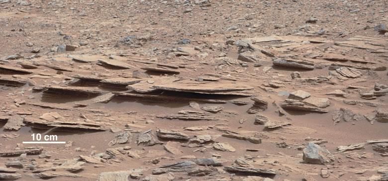
13

Figure 3. 'Ireson Hill' on Mount Sharp, Mars. Picture taken by Curiosity Mars rover’s Mastcam

Figure 4. Photograph taken by NASA's Mars Curiosity rover in 2017. It shows the 'Vera Rubin Ridge'. Credit:
NASA/JPL-Caltech/MSSS

Figure 5. Photograph taken by NASA's Mars Curiosity rover in 2012. It shows a portion of a rock outcrop
inside the Gale Crater. Credit: NASA
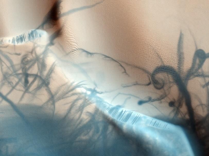
14

Figure 6. Dust devil tracks on Mars. Credit: NASA/JPL/University of Arizona

2.2 The wheels of a Rover
Wheels take an important part on the traction of the rover as they are the only
part in contact with the surface. A rover is a vehicle designed to climb many
different surfaces as steep slopes, sand dunes and more, for that reason, the
wheels need to be also specially designed for those tasks. On Earth, the wheels
that regular cars use are normally pneumatic tires, made from synthetic or natural
rubber, that materials are not suitable for space applications. On Mars,
temperatures can get to -150 ºC, at that temperature the rubber would convert
into a rigid-solid material as rubber’s glass transition temperature is -70º C
approximately. Rubber would become fragile, and in addition, rubber is heavy.

To understand why rovers use wheels there is next a quick overview to the main
locomotion principles and locomotion systems that currently exist.

Here are stated 4 locomotion principles for robots to move:

 • Walking
 • Rolling
 • Hopping
 • Hybrid
15

Walking:

Robot walking try to simulate human walking, this type of locomotion is very
efficient in climbing uneven surfaces and has good capability of obstacle
crossing.

Rolling:

Are the most efficient system in terms of energy efficiency on flat surfaces. In
ideal rolling a wheel does not lose energy, compared to walking that each time
the leg impacts the ground is losing energy.

Hopping:

It has been proved that a robot with just one leg and a small foot can stay upright
by simply hopping.

Hybrid:

It is called Hybrid locomotion to a robot that performs locomotion in multiple ways.
16

Also, there are different locomotion systems to perform the job; here are stated
the wheeled, legged, tracked and hybrid.

See table 1.

Table 1. Synthetic comparison of locomotion system features. Article: Locomotion systems for ground mobile
robots in unstructured environments

According to the table the wheeled system is the most energy efficient, less
mechanically complex and the less control complex, also as energy efficiency is
hugely important on Mars because energy in rovers is limited, the wheeled
system is the most reliable. For these reasons, the wheeled system is the most
used in rover space missions.

2.2.1 The Lunokhod 1
On November 17th, 1970, the automatic space station “Luna 17” made by the
Soviet Union descended and landed on the surface of the Moon. It deployed a
17

remote-controlled lunar rover named Lunokhod 1, being the first mobile vehicle
on the surface of the Moon.

Its goal was to travel to various locations and conduct lunar soil tests under the
control of the operation center on Earth.

The Lunokhod 1 weighted 756 kilograms and had dimensions of 1.35m (height)
x 2.15m (length).

 Figure 7. Picture from the Lunokhod 1

The Lunokhod 1 implemented an automatic “self-propelled” chassis where the
motors of rover to propel itself were located inside the wheel. In Figure 8 it can
be seen an illustration of the motor in-wheel module of the Lunokhod 1.
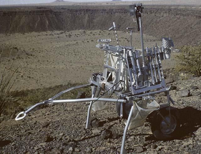
18

Figure 8. Motor inside the wheel of the Lunokhod-1 self-propelled chassis (drawing made by V.V.Grinev)

With the self-propelled chassis, an eight-wheeled model was contemplated as
the main propulsion system. It suited the dimensions of the landing module and
it also suited the requirements of high cross-country capability and stability. Each
of its 8 wheels were rigid rim wired meshed with bicycle-type spokes and metal
cleats for incrementing traction; their dimensions were 510 mm in diameter and
200 mm in width, they could be controlled independently for different speeds. It
also allowed the rover to make an almost 0 degree turn radius, this rotation is
achieved by controlling the speed of the wheels on the opposite sides. In fact, the
wheels had to be rigid due to the significant axial deformation of an elastic wheel.

2.2.2 MET-ROVER
The MET (Modularized Equipment Transporter) was a two-wheeled vehicle used
by the Apollo 14 mission, it worked as a portable workbench carrying the lunar
hand tool carrier, the geology tools, the closeup stereo camera, two 70 mm
Hasselblad cameras, a 16 mm data acquisition camera, film magazines, a
dispenser for sample bags, a trenching tool, worktable, sample weigh bags and
the Lunar Portable Magnetometer [2].

The wheels were 400 mm in diameter and 100 mm wide, and were filled with
nitrogen gas, being the first tires on the Moon. The tires were designed by
Goodyear Tire and Rubber Company, and it faced one big challenge; NASA
required Goodyear to make a tire where the inflation pressure had to be 1.5 psi
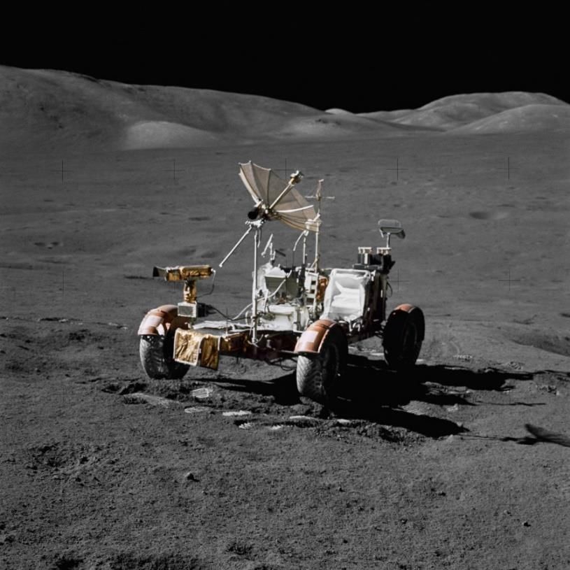
19

on the surface of the Moon. It was a difficult challenge because a tire with 1.5 psi
on Earth, has 16.2 psi on the surface of the Moon (that is because on Earth the
atmospheric pressure is 14.7 psi and on the Moon is non-existent). The problem
was solved pre-inflating partially the tire so that it reached the 1.5 psi pressure on
the surface of the Moon.

Figure 9. Left: MET prototype used by the Apollo 14 astronauts for their surface simulation training. Right:
Picture of the Goodyear's MET Wheel

2.2.3 Lunar Roving Vehicle
The Lunar Roving Vehicle or LRV was an electric vehicle made to be driven in
the low gravity conditions of the Moon, and to travel through the lunar terrain so
the astronauts could get further than the past missions, extending the mission
capabilities. The first LRV sent on the Moon was on the Apollo 15 mission and it
was driven for 27.8 km in 3 hours and 2 minutes of driving time.
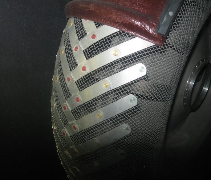
20

 Figure 10. Picture of the Lunar Roving Vehicle taken during the Apollo 17 mission. (Credit: NASA)

The LRV had a total mass of 210 kg but was designed so it could carry an
additional payload of 490 kg on the lunar surface. Its dimensions were 3.1 meters
long with a wheelbase of 2.3 meters and a height of 1.14 meters. The wheels of
the LRV were composed by an aluminum hub and a rigid rim where a steel wire
mesh was attached to it. The steel mesh was an 818 mm in diameter and 230
mm wide zinc coated mesh with 0.83 mm diameter steel strands attached to the
rim. titanium chevrons covered 50% of the contact area of the wheel to provide
more tractions.

Figure 11. Left: Close-up photograph showing the chevrons shape treads of the Lunar Roving Vehicle
Wheel. Picture taken in the ‘Apollo to the Moon’ exhibition at the National Air and Space Museum in
Washington, D.C. Right: Photo of the Lunar Roving Vehicle Wheel
21

2.2.4 Sojourner
Following the successful landing on the Moon of the Apollo Program, NASA
aimed to another challenge, Mars Exploration. The Mars Pathfinder landed on
Mars on July 4th of 1997, carrying a rover named Sojourner. The goal of the
Pathfinder was to land successfully and deploy what will become the first wheeled
vehicle to operate on another planet.

Figure 12. Picture of the Sojourner Rover near "The dice" (letf). Picture of the Sojourner Rover Wheels
(right). (Credit: NASA/JPL)

The Sojourner, also known as the Microrover Flight Experiment (MFEX), is a 6
wheeled vehicle that weights 11.5 kg, has a normal height of 280 mm, being 630
mm long and 480 mm wide. The 6 wheeled chassis of the rover was chosen over
a 4-wheel design because it provided greater stability and obstacle crossing
capability, also 6-wheeled rovers can overcome obstacles 3 times bigger than 4-
weeled rovers. Also, the 4 corner wheels are independently steerable to be able
to turn in place. This 6-wheeled chassis has a rocker bogie suspension
mechanism designed by the JPL (Jet Propulsion Laboratory) to allow the rover to
traverse obstacles 1.5 his wheel diameter in size and providing added stability to
the vehicle, without using springs.

 Figure 13. Diagram of the Rocker-Bogie mechanism
22

The wheel itself has a diameter of 130 mm, 80 mm of width, and they are made
of aluminum, with stainless steel treads and cleats on the wheel to provide better
grip on rocky surfaces and improved traction on soft sand [3].

2.2.5 Mars Exploration Rovers
After the Pathfinder, the next mission to Mars was the Mars Exploration Rovers,
the Spirit (MER-A) and the Opportunity (MER-B), this mission is part of the Mars
Exploration Program. They were launched on 2003 and landed in January 2004.
The mission had 4 main goals [4]:

 1. Determine whether life ever arose on Mars.
 2. Characterize the climate of Mars.
 3. Characterize the geology of Mars.
 4. Prepare for human exploration.

The Rovers dimensions are 1500 mm high, 2300 mm wide and 1600 mm long,
with a total mass of 180 kg. As the Sojourner, a rocker-bogie mechanism has
also been used in their 6-wheeled rover, which allow the rovers to go over rocks
or through holes that are bigger than a wheel in diameter. The MER apported an
improvement to the mobility of the vehicle; the Sojourner’s rocker bogie
mechanism was modified for the Mars Exploration Rover Mission, also, the
mobility system of the MER rovers is in the back of the vehicle because the
difference in weight and center of gravity from the Sojourner. The wheels are
approximately 260 mm in diameter, almost twice larger than the Sojourner’s, and
incorporates a new design; a spiral shape that connects the outer part of the
wheel with the hub to provide safety and stability by absorbing shocks during
movement.

 Figure 14. Pictures of the MER Rovers Wheels. See the spiral pattern of the wheel. (Source: NASA)
23

The wheels also have cleats, to improve traction on soft soil and climbing
conditions, and the orange filling of the wheel is an open-cell foam called
solimide, a composite with good flexibility in low temperatures (ideal for Mars), it
was bonded to the wheel, filling the empty spaces between the spiral shape in
order to prevent rocks, dust and other stuff, to get inside the wheel, possibly
interfering the mobility of the rovers.

But the Opportunity and Spirit become stuck on soft soil. The rovers lost traction
while driving through loose sand conditions. The Opportunity’s wheels were
buried in sand and after several simulations and tests, NASA's Jet Propulsion
Laboratory in Pasadena, California, (JPL), achieved to move the rover and free
him. But with the Spirit, NASA tried several attempts and could not release him,
as the wheels were not able to generate traction at all, it then became a stationary
science platform.

2.2.6 Curiosity
The Curiosity was the Rover of the Mars Science Laboratory Mission, its mission
was to explore the Gale Crater in order to know if Mars ever had the right
environmental conditions to support small life forms. The Curiosity was the most
complex machine ever sent to another planet, with two different brains to process
information, six-wheels, seventeen cameras, a robotic arm, nuclear powered, and
even a laser to analyze rocks from distance.

Compared to the last rovers, Curiosity was huge; weighing almost 1 ton (899 kg),
3000 mm long, 2700 mm wide and 2200 mm tall (like the size of a small SUV).
24

Figure 15. A picture of the three JPL Mars Rovers. Front and center is the flight spare of the Sojourner, Marie
Curie. On the left is the Surface System Test Bed (SSTB) of the Mars Exploration Rover. At right is the
Vehicle System Test Bed (VSTB) nearly identical to the Curiosity Rover [5]. (Credit: NASA/JPL-Caltech
PIA15279)

The Mars Science Laboratory introduced a new challenge, to land something
considerably large. Chief engineer Rob Manning wrote in a 2014 mission memoir:
“We came to realize that we did not know how to land anything on Mars reliably,
let alone something large”. NASA’s Jet Propulsion Laboratory (JPL) formed a
team to identify and design the technology it was needed to be able to precisely
land a large rover on Mars. The engineers analyzed two different strategies for
the final stage of the landing, previously successful landings: the Viking landing,
and the Pathfinder’s landing. The Viking lander employed retrorockets to slow the
descent to a near-standstill and then dropped the spacecraft to the ground. In
other way, the Pathfinder used a different approach, the spacecraft was folded
into a tetrahedron fitted with airbags, that hung from a rope below a rocket pack
connected to a parachute. At the last moment (100 meters above the surface)
the airbags inflated, and the rope cut [5].

Neither options fitted the Mars Science Laboratory mission, it was too heavy for
both landings; if the Viking strategy was used, the landing would be too unprecise,
but the Pathfinder strategy couldn’t be used as well, as the airbags had a
maximum payload of 200 kg. A combined landing strategy was the correct
strategy.
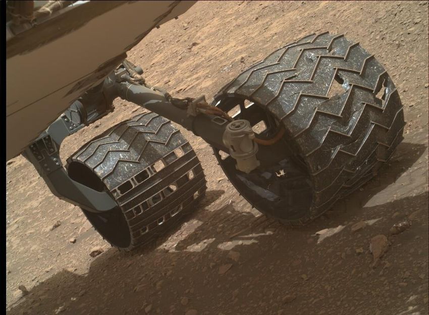
25

 Figure 16. This image shows the Entry, Descent and Landing sequence. (Credit: NASA)

Using this Entry, Descent and Landing sequence, the Curiosity’s wheels had to
resist the impact of the landing, absorbing the mechanical shock of the
touchdown so the rover itself could not get harmed. Also, they needed to be as
lightweight as possible, and they had to provide traction in all the possible landing
scenarios. The wheels have a crowned profile being 500 mm in diameter at their
centers and 465 mm in diameter at their edges. They have 400 mm of width. The
wheels consist of an aluminum tire machined from a block of aluminum, and a
titanium hub and spokes. The spokes have a complicated shape that allow them
to deform in every direction. The wheels are very thin, only 0.75 mm, in order to
reduce the mass of the wheels, but thick enough so it wouldn’t puncture if all the
rover’s weight rested on a single point over a pointy rock. For traction, the wheels
incorporated treads or “grousers” on the surface of the wheels and chevron
pattern features to avoid slipping downhill. All this together, make the wheels to
deform and return to the original shape [5].
26

 Figure 17. Diagram of the Curiosity's wheel. (Credit: NASA/JPL-Caltech/Emily Lakdawalla)

The Curiosity carried a rocker-bogie mechanism for travelling more stable
through Mars terrain. The “rocker” arm is attached to the front wheels and is the
longer one. The middle and rear wheels are attached together to form a “bogie”,
that is connected to the rocker part with a pivot that allows 45º tilting. The rocker
is also attached to the chassis with a pivot that can tilt as much as 20º. Each side
of the rover has a rocker and a bogie, and they are connected in the chassis via
a mechanical differential pivot, so the movement on each side of the rover doesn’t
affect the other side. The chassis maintains stable, it keeps an average of the
pitch angle of both rockers. This mechanism is extremely useful on climbing tilted
surfaces because it allows the rover to have the six wheels in contact with the
surface all the time, maintaining traction on the wheels while the rover is climbing.

2.2.7 Wheel degradation on Curiosity’s wheels
Curiosity’s wheels showed wear at Sol 411 during a routine examination of the
wheels. NASA noticed a puncture on the front left wheel of the rover, although
the puncture was not very significant, it got worse and grew over time. The team
reinspected the wheels on Sol 463 noticing the growth of the puncture and
scheduled numerous detailed wheel inspections. This was not the only damage
on the wheels, more tears appeared on all the wheel but not on the rear wheels.
The punctures were cause by two main factors: metal fatigue of the stress during
rotations, and forces caused by the rocker-bogie mechanism. The motors of the
wheels act at fixed rotation rates, so when a wheel finds an obstacle to climb, the
wheel must travel more distance (and more vertical) than the other wheels while
27

moving at the same speed, this causes the wheel to suffer a considerable force
[5].

 Figure 18. Curiosity’s wheels punctures. (Credit: NASA)

Having a damaged wheel on Mars was not something that could be fixed so the
team had to be extremely careful on where to locate the rover so it would not get
more harmed, or even get the rover stuck.

2.2.8 Perseverance
The Perseverance is the rover of the Mars 2020 mission, a rover mission that
forms part of the NASA’s Mars Exploration Programme. This rover landed on the
February 18th of 2021. The Perseverance rover was similar to the Curiosity but
introduced a redesign of the Curiosity’s wheels in order to avoid punctures and
more damages.
28

Figure 19. The aluminum wheels of NASA's Curiosity (left) and Perseverance rovers. (Credit: NASA/JPL-
Caltech)

The wheel changed in size, reducing width, being more narrow but larger in
diameter (526 mm) and made of a thicker aluminum, so overall the wheel weights
more and is more robust. Also, the tread profile has been redesigned to avoid
punctures and tears over sharp, pointy rocks.

2.2.9 ExoMars 2022
The ExoMars is an astrobiology program by the European Space Agency that will
search for signs of past life on Mars, overall. The mission will land the first
European rover on the surface of Mars, and it is planned to land in 2022. The
rover, named Rosalind Franklin will combine the capability to travel through Mars
and to study the planet at depth. The rover changed the tendency of NASA of
building a rocker bogie mechanism on their rovers and ESA studied the different
suspension mechanism that the rover could use. Two main mechanisms were on
the spotlight: the 3-bogie mechanism and the JPL rocker bogie mechanism.
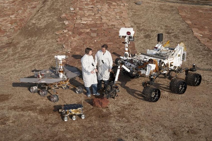
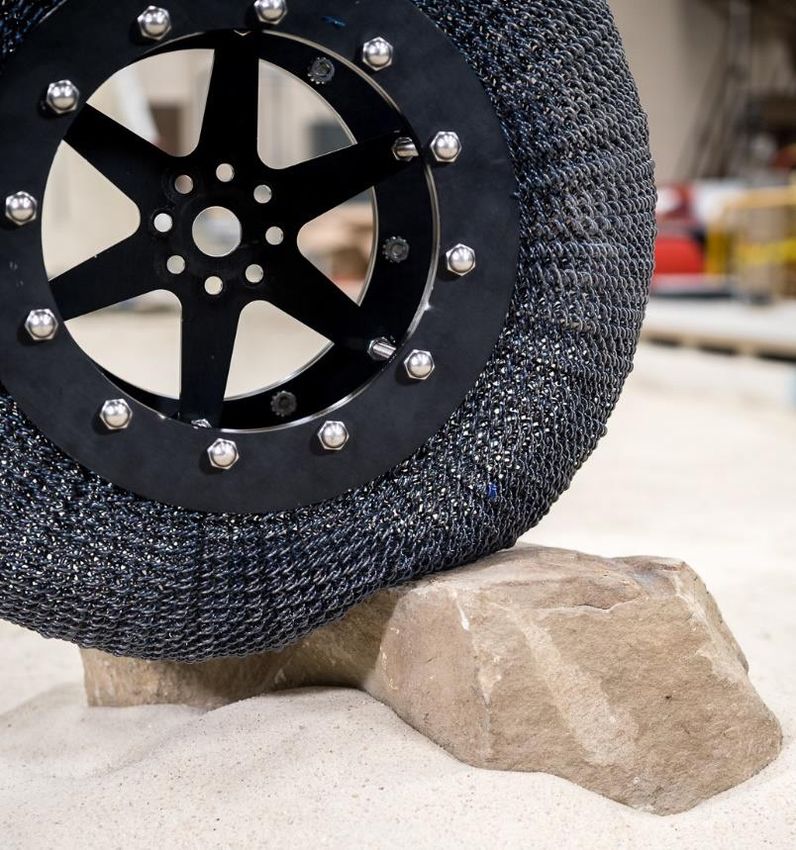
29

Figure 20. In the picture is showed some of the different possible mechanisms concepts that the Rosalind
Franklin rover could carry

In Figure 20 it can be seen the 3-bogie mechanism and the rocker bogie
mechanism. The 3-bogie consists in two independent longitudinal side bogies
and one transverse bogie. Both concepts were compared and the 3-bogie was
the one selected for the rover as “it was found to be the lightest, least complex,
provided sufficient stability with a footprint that could be stowed within the lander
volume envelope, and offered step obstacle climbing performance that was better
or comparable with the other short-listed concepts.”(Patel et al., 2010).

The peculiar feature of the mobility system of the rover is the 6 flexible metal
wheels that can deform without damage. The wheels are 250 mm in diameter
and a width of 100 mm, with a rigid aluminum hub connected to 3 flexible steel
bands as spokes, allowing possible deformation to the flexible rim. Two ‘bump
stop discs’ protect the spokes from over deflecting when subjected to high loads.
The European Space Agency investigated the advantages of flexible wheels in
front of rigid wheels, and to explore the capabilities of them.
30

 Figure 21. The ExoMars rover Rosalind Franklin's wheels. (Credit: ESA)

2.3 Flexible wheels and their interaction with different soil
conditions
A flexible wheel is a wheel that its contact surface (tire) deforms in normal
operating conditions, without excess loads. This means that the wheel can have
a larger footprint than a rigid wheel with the same nominal diameter. The wheel
deforms under the rover’s mass and depending on the different soil conditions.
Mars rovers wheels are usually made of metal, due to the threatening conditions
they have to go through; high radiation, thermal stress and high vacuum
conditions. Normal rigid wheels have an average of deformation of 10%, flexible
wheels can deflect more than 10% without breaking.

In Figure 22 there is illustrated the possible different ways that a wheel can
interact with the surface. In the first scenario is represented a rigid wheel driving
on deformable terrain, the wheel does not show deformation because rigid
wheels have an average deflection of less than 10% of the diameter. In the
second illustration is shown a flexible tire going over the same surface than in the
first one, in this case the wheel deflects about more than 10% the diameter of the
wheel. The wheel maintains most of its original shape, but it gets flat on the
contact area with the ground. In the third image it is illustrated a flexible metal
wheel driving on deformable terrain. This flexible metal wheels can deform more
than 10% of the wheel’s diameter and are made of thin metal layer to provide
elastic properties. The wheel behaves adapting an ellipse shape while in contact
with the surface, having more surface in contact, thus providing more traction [6].
31

 Figure 22. Possible wheel interactions with the surface [6].

By incrementing the amount of surface in contact means that less pressure will
be applied to the ground. To explain this fact a bit more some equations have
been used to show the relation between surface contact and pressure.

Being P the pressure of the wheel applied to the ground, the weight of the
wheel and A the surface of contact or area:

 = (2.1)

The area of contact with the ground is also the width of the contact patch ( )
multiplied by the length of the contact patch ( ):

 = (2.2)

The side length is also:

 = 2√ ( − δ ) (2.3)

Where δ is the deflection resulting from the weight of the wheel , and D the
diameter of the wheel. Hooke’s law of elastic deformation gives the rate of
deformation of a body c, by dividing by δ:

 = (2.4)
 δ

Putting together these equations, ground pressure is obtained more detailed:

 = (2.5)

 2√ ( − )

So, by increasing the surface of contact of the wheel with the ground, the
pressure that the wheel applies to the ground is directly lowered, meaning that a
32

bigger surface of contact contributes in a less sinkage of the wheel, providing
better performance.

Energy efficiency is hugely important on rover missions as it is directly impacting
rover’s energy consumption. Energy of rovers can be limited, and its consumption
directly affects on how much the rover can operate without recharging, the weight
and dimensions of the battery pack and can even affect on the ability of the rover
to climb surfaces, as a much more energy efficient system will allow the rover to
climb much more difficult surfaces with less effort. Even though a flexible wheel
is a bit less energy efficient than a rigid wheel, the benefits of flexible wheels
overcome the loss of energy efficiency, and if an adaptive wheel could be used;
a wheel that can adapt to different type of surfaces, it might lead to a more energy
efficient system.
33

2.4 Summary
The fact that rigid wheels have caused some problems in the past even though
they have been used for almost all rovers raises questions about the design and
the concept of these. In fact, many studies have proved the advantages of flexible
wheels in front of rigid wheels, lowering the ground pressure so it performs better,
improves the durability, and provides better traction. It has also been proved
through several studies that the performance of the Spirit, in the conditions that
got him stuck, would have improved if instead of the rigid MER wheels, flexible
wheels would have been used.

Seeing the struggle that the Curiosity had with his wheels has made the scientific
and technological community focus on the design of new wheels. In fact, the next
section, provides an investigation of a new concept of flexible wheels that is
expected to be used in future lunar and Martian missions.
34

 Part III

SHAPE MEMORY ALLOY
 WHEEL
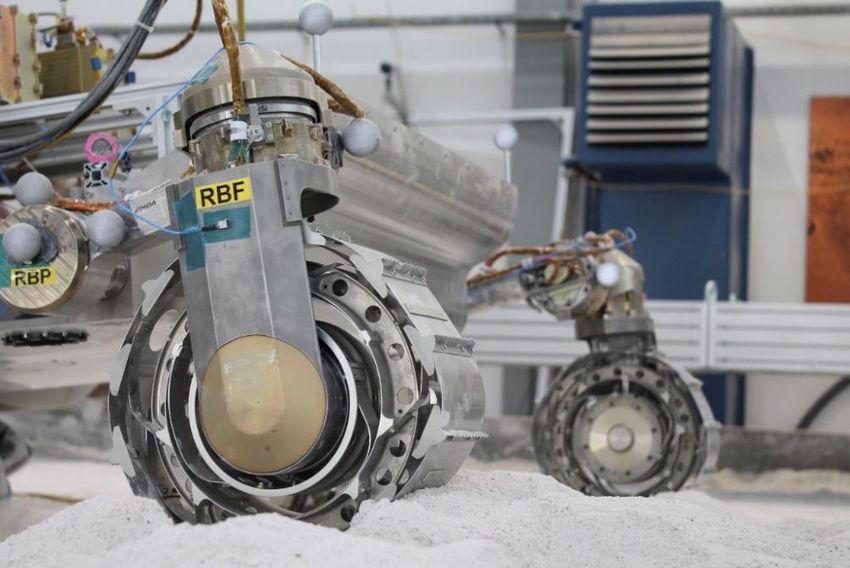
35

3.1 Concept
Mars rover wheels have been in constant development since the first mission,
going through classic spoke wheels, rigid and finally to flexible wheels. Even if in
the Moon, a flexible wheel was used, the concept of a flexible wheel for Mars it
has not been used at the moment. The ExoMars will be the first mission to
introduce the concept of a flexible wheel in its rover and it will be a huge step
forward for the next generation of, not only rovers, but any type of vehicles used
in Mars in the future. Also, humans landing to Mars is the next aim for space
agencies, so all kind of development is currently going on.

While NASA was developing the next Mars exploration rovers, they wanted to
take a look back to the Moon and reinvented the lunar wheel, developing new
designs with newer materials, technologies, and a better functionality. Indeed, the
wheel is a redesign or evolution of the ‘spring tire’ invented by NASA Glenn and
their industry partner Goodyear, inspired by the Lunar Roving Vehicle wheels.
The spring tire is a concept of flexible wheel designed during the mid-2000s by
NASA and Goodyear. This spring tire is a wheel that consist in several hundred
coiled steel wires woven into a flexible mesh, allowing the tire to support high
loads while deforming so it can adapt to the surface. But for Mars it needed a
better design, even though the spring tire performed good in traction and
durability, for Mars NASA Glenn engineers thought it was needed to improve
traction in soft sand, durability and reduce overall weight [7]. So, several
prototypes were developed to improve those features.
36

 Figure 23. Comparison of Mars Spring Tire (MST) Prototypes. (Credit: NASA)

The prototypes were tested in NASA’s Jet Propulsion Laboratory (JPL) and even
though they performed well they noticed plastic deformation of the steel wires
when rolling over very punishing terrain simulating Mars surface. The project got
stuck until engineer Colin Creager and Materials Scientist Santo Padula had a
conversation about a new material that could work in the tires instead of spring
steel, this changed the overall direction of the project [7].

The new concept of wheel for Mars exploration rovers that NASA has been
developing consists in a shape memory alloy mesh that can withstand excessive
deformation without permanent damage and recovering its original shape after
the stress is removed.

In this part it is going to be explained in detail the material and the design of the
wheel, testing its functionality and its viability.
37

Figure 24. Picture of a Shape Memory Alloy wheel tire developed by NASA. (Credit: NASA)
38 3.2 Material The material used for the wheels is a Shape Memory Alloy (SMA) called Nitinol. Nitinol is a metal alloy normally composed by roughly 50% nickel and 50% titanium, that has Shape Memory Effect behavior as well as superelasticity. It was discovered in 1959 during a Naval research project. This material has plenty of applications on biomedicine due to his specific properties, like biocompatibility and good magnetic resonance imaging opacity (to be seen by X-ray, for example), but it has applications in plenty of other areas, like structural engineering, thermal and electrical actuators, and more. But the most interesting property for the purpose of a wheel is the superelasticity, that allows the alloy to act as a super spring. 3.2.1 Properties Nitinol has two main properties that characterizes him, the shape memory alloy effect and the superelasticity. The Shape Memory Alloy effect is the capability of the alloy to “memorize” its shape before stressed is made upon the alloy, in a way that the metal can recover its own shape. Nitinol doesn’t behave as conventional materials. When conventional materials are deformed under stress, the atomic bonds are getting stretched to deform. This type of materials have a unique characteristic, that allow him to make an atomic rearrangement when stress is induced and deformation occurs. That allows the material to deform about 30 times more than a conventional material without plastic deformation (permanent deformation). Conventional materials like steel, aluminum, brass, and similar elastic-plastic materials show plastic deformation after a strain of 0.3-0.5%, so his elastic range (range where deformation is recoverable) is only bellow that strain. This amount of deformation limits many applications and uses. In the other hand, Nitinol and other shape memory alloys can achieve a strain of 8-12% before showing significant plastic deformation. But Nitinol is not the only material suitable for a tire, there is a list of materials that show shape memory effect or superelasticity that could also be used to produce a tire, for example; silver cadmium (Ag-Cd), copper-based alloys (Cu-Al-Ni, Cu-Sn, etc.), iron-based alloys (Fe-Ni-Co-Ti, Fe-Mn-Si, etc.), nickel-based alloys and many others, but the most used and effective materials are Ni-Ti, Cu-Zn-Al, and Cu-Al-Ni.
39

It takes profit of the temperature effect making the structure of the metal to
change between different phases, this phase transformation is called martensitic
transformation. When the metal is at high temperatures, Nitinol adapts a simple
cubic structure known as austenite, and remembers the shape in this high
temperature state. At low temperature it converts into a more complicated
monoclinic crystal structure known as martensite. The change between these two
structures is the main factor causing the shape memory effect. In the next figure
it can be seen the general hysteresis loop of a Shape Memory Alloy.

 Figure 25. Thermal hysteresis loop of a Shape Memory Alloy [8].

The hysteresis loop shows the change of the alloy composition through different
changes in temperature. When the alloy is cooled, the structure starts to
transform to martensite, and at high temperatures the alloy adapts an austenite
form. From full austenite, martensite starts to form as the alloy is cooled to the
 , martensite start temperature. It keeps forming martensite until all the structure
is only martensite, the temperature where the transformation is completed is
known as , or martensite finish temperature. Similar happens when its heated.
Starting from full martensite, the alloy is heated, and it starts to form Austenite at
 , or austenite start temperature, and the transformation finishes at the , or
austenite finish temperature, where all the alloy is full austenite.

While being in stable martensite structure (bellow ), if the metal is deformed, it
causes non-plastic deformation maintaining the martensite crystal structure, this
deformation is known as de-twinning, and it consists in the rearrangement of the
atomic structure without breaking atomic bounds, so the atoms are connected the
40 same way all the time. When the load is removed, the martensite elastically recovers a small amount of deformation. Heating above the temperature, when the structure is full austenite, makes the material return to its original shape 3, as the austenite phase memorizes its macroscopic shape. Figure 26. Left: Load-Temperature diagram of a SMA material. Right: Schematic that shows the behavior of the crystal structure of two different type of materials when they undergo deformation; above, a conventional metal and below a superelastic material. In Figure 26 it can be seen how the cycle of temperature-load of a material like Nitinol. If austenite is cooled martensite starts to form creating a twinned structure (the alloy form groups that are imaging themselves over a plane, each group being reflections from each other), after loading that same structure a process known as detwinning starts on the martensite, and if heating is applied to the deformed martensite it starts forming austenite, recovering the shape that it had before (when “original” austenite). On the right of Figure 26 its pictured how two different materials behave while undergoing deformation. The material from the upper part of the picture it’s a conventional material like stainless steel that when undergoes deformation, the crystal blocks slips, that means that exists a permanent displacement of one part of the crystal structure relative to another one, so it suffers permanent deformation, i.e., plastic deformation. The material at the bottom of the image is Nitinol on its martensitic phase (already twinned structure), that when it undergoes deformation instead of causing slip, the crystal structure starts detwinning, that means that an atomic rearrangement is done so it can deform without permanent deformation; meaning that the atoms keep the same bonding than before. Therefore, when austenite is achieved after the deformation in martensitic state, the original austenitic structure is recovered regardless of the deformation in martensitic state. Also, Nitinol is an intermetallic
41

compound, that means that in difference from ordinary alloys, the atoms (nickel
and titanium) have a very specific position in the structure, facilitating the shape
memory effect. The ability of Nitinol to switch between these two crystalline
structures is what gives the alloy its shape memory properties.

But the most interesting property of the Nitinol it is the superelasticity. A main
fact that causes this effect is that it is possible to form martensite only with stress
applied, without involving cooling factors. Therefore, in a certain range of
temperature, if stress is applied on austenite it starts to form martensite at the
same time that deformation occurs. In this case, when the load is removed, the
martensite becomes unstable, and it causes the martensite to recover its
austenitic phase and original shape. This is extremely important for the
applications of Nitinol in the Mars rover or in any space application. Having a
compound that is able to deform and fully recover its shape without giving any
type of energy has plenty of ways to be useful.

Figure 27. Schematic of the superelastic behavior of Nitinol, when found above the austenite finish
temperature, Af, and bellow the martensite deformation temperature, Md. Starting at a) on full austenite
structure. Stress is applied on the austenite structure forming a twinned structure shown on b), and at the
same time forming martensite. The structure is keeping loaded until c) when it transforms the material into
full martensite. Continuing loading the martensite until d) causes elastic deformation on the structure. If
stress is removed from d) it elastically recovers until c) and if unloading is continued it forces the
transformation of austenite on e) until it fully transforms to austenite on a) when unloading is complete and
no stress is applied anymore [9].

Nitinol needs to be in full austenite to has superelastic properties, so depending
in which temperature the is found is extremely important in having a spring
tire. Anyway, Nitinol superelastic properties are found in a small range of
42 temperatures above , approximately 40 degrees above . This limit of temperature is known as , the limit of temperature where superelasticity can be found; bellow this temperature is possible to form martensite under load due to twinning, above this temperature, since martensite cannot be formed under load, it deforms plastically. But it is possible to change the temperature of to vary the range of temperatures that the superelastic properties are found, in order to adapt to the desired conditions. This is done by changing the composition of nickel and titanium of the alloy. Nitinol is most likely composed of 50-51% nickel by atomic percentage, and 55- 56% by weight percentage. If the composition of nickel/titanium is changed, the transformation temperature (temperature when Nitinol start to behave as a superelastic material) also changes. Therefore, the range of superelasticity can be controlled by changing the ratio of nickel to titanium in the alloy. Figure 28 shows how the Nitinol’s composition affects the point of martensitic transformation ( ). As nickel increases in Nitinol’s composition, the Ms temperature decreases, it can decrease that much that it is possible to have superelastic properties on Nitinol at room temperature (20ºC). This is extremely important on Mars aplications. Figure 28. The variation of the martensitic transformation temperature by the change on Nitinol’s composition
43

Mars temperatures can vary a lot. According to the measures the Curiosity rover
made on the Gale Crater, the maximum temperature recorded by the rover was
20ºC and the minimum was -127ºC. Even though these were the maximum and
minimum in a whole year, average temperatures in mars go from -5ºC to -80ºC.
So, for sending superelastic Nitinol to Mars, it needs to behave in this huge range
of temperatures. Is a big challenge to set Nitinol to behave superelastically in
such changing temperatures, just because the superelastic window is only 40
degrees approximately above .

Figure 29. Stress-strain curves at room temperature of two compositions of Nitinol; a superelastic Nitinol
( = +10º ) and thermal martensite Nitinol ( = +110º ) [10].

To understand more how superelastic materials differ from conventional SMA
materials, in Figure 29 is represented a stress strain diagram to show how the
two types of Nitinol behave on different loads at room temperature, and how much
they deform with the same stress applied. The two types of Nitinol pictured in the
figure are the 49−9 50−1 ( = +10º ) superelastic austenite at room
temperature (20ºC) and the 49−7 50−3 ( = +110º ) thermal martensite at
room temperature. As it can be seen in the diagram the superelastic Nitinol has
a higher stress plateau; when stress induced martensite starts to form than the
thermal martensite structure; when twinning and deformed martensite happens,
meaning that superelastic Nitinol can allow more stress until it starts to deform
significantly [10].

3.3 Structure
The design of the Lunar Roving Vehicle tire was not optimal for Mars, Mars gravity
is higher than on the Moon and the LRV only had 450 kg of mass compared to
44 the almost 1000 kg of the Curiosity, so it had to support much heavier loads, travel faster, improve traction and improve durability, all of that made the tire unsuitable. To change the wire diameter was not an option as its application was limited by two main factors: 1. Contour terrain capability was lost. 2. Loss in durability caused by the increment of wire stress. Using the original wire mesh from the LRV to accomplish the requirements was too limited. Using helical spring geometries on tires have been proved to have many advantages over normal wire mesh tires like additional flexibility, higher carrying capability and better performance like traction, especially in soft soil conditions, also spring geometries are a way to store energy so there is little energy loss when deformation occurs. But the use of conventional materials like steel, aluminum and alike have problems of plastic deformation. These materials show elastic properties until an amount of deformation of 0.3% after this they enter the range of plasticity, where permanent deformation occurs. Due to this amount of deformation, helical spring geometries can be useful in these materials as they limit the amount of strain that is applied on the material while deformation occurs, so more deformation can be achieved before entering in the range of plasticity. Increasing the diameter of the wire for avoiding permanent deformation is not an option as well, as it carries a huge increment of the material mass, cost and in some cases, an increase of 500% in metal volume, also reducing the performance of the material [11]. In the wake of the problems with plasticity (permanent deformation), SMA introduced a solution to this deformation issues. The innovative wheel keeps the helical spring geometries but replaces conventional materials for shape memory alloys, in order to achieve a much significative strain without permanent deformation. As it has already been explained, SMA can improve the amount of strain before irreversible deformation. In conventional materials the strain before plasticity occurs is about 0.3-0.5%, and in SMA materials it can get up to 8- 12%, that means that SMA can deform almost 40 times more than conventional materials before plastic deformation. That increases the utility of the material and of the spring wheel itself. Having a material that can deform more without losing
You can also read