Microstructural characterisation of thick-walled wire arc additively manufactured stainless steel
←
→
Page content transcription
If your browser does not render page correctly, please read the page content below

Microstructural characterisation of thick-walled wire arc
additively manufactured stainless steel
Citation for published version (APA):
Palmeira Belotti, L., van Dommelen, J. A. W., Geers, M. G. D., Goulas, C., Ya, W., & Hoefnagels, J. P. M.
(2022). Microstructural characterisation of thick-walled wire arc additively manufactured stainless steel. Journal
of Materials Processing Technology, 299, [117373]. https://doi.org/10.1016/j.jmatprotec.2021.117373

DOI:
10.1016/j.jmatprotec.2021.117373

Document status and date:
Published: 01/01/2022

Document Version:
Publisher’s PDF, also known as Version of Record (includes final page, issue and volume numbers)

Please check the document version of this publication:
• A submitted manuscript is the version of the article upon submission and before peer-review. There can be
important differences between the submitted version and the official published version of record. People
interested in the research are advised to contact the author for the final version of the publication, or visit the
DOI to the publisher's website.
• The final author version and the galley proof are versions of the publication after peer review.
• The final published version features the final layout of the paper including the volume, issue and page
numbers.
Link to publication

General rights
Copyright and moral rights for the publications made accessible in the public portal are retained by the authors and/or other copyright owners
and it is a condition of accessing publications that users recognise and abide by the legal requirements associated with these rights.

       • Users may download and print one copy of any publication from the public portal for the purpose of private study or research.
       • You may not further distribute the material or use it for any profit-making activity or commercial gain
       • You may freely distribute the URL identifying the publication in the public portal.

If the publication is distributed under the terms of Article 25fa of the Dutch Copyright Act, indicated by the “Taverne” license above, please
follow below link for the End User Agreement:
www.tue.nl/taverne

Take down policy
If you believe that this document breaches copyright please contact us at:
openaccess@tue.nl
providing details and we will investigate your claim.

Download date: 25. Feb. 2022
Journal of Materials Processing Tech. 299 (2022) 117373
Contents lists available at ScienceDirect
Journal of Materials Processing Tech.
journal homepage: www.elsevier.com/locate/jmatprotec
Microstructural characterisation of thick-walled wire arc additively
manufactured stainless steel
L. Palmeira Belotti a, J.A.W. van Dommelen a, *, M.G.D. Geers a, C. Goulas b, W. Ya c, J.P.
M. Hoefnagels a
a
Eindhoven University of Technology, Department of Mechanical Engineering, P.O. Box 513, 5600 MB, Eindhoven, the Netherlands
b
University of Twente, Faculty of Engineering Technology, Department of Design Production & Management, P.O. Box 217, 7500 AE, Enschede, the Netherlands
c
RAMLAB BV, Scheepsbouwweg 8 F6, 3089 JW, Rotterdam, the Netherlands
A R T I C L E I N F O A B S T R A C T
Associate Editor: Rajiv Mishra Wire arc additive manufacturing (WAAM) is a class of technologies suitable for producing large parts due to its
high material deposition and building rates. Among the many possible materials processed by WAAM, austenitic
Keywords: stainless steels, e.g. 316L, are commonly employed. The structure of WAAM 316L thin parts has been studied
Wire arc additive manufacturing extensively before. However, multiwalled or thick WAAM 316L parts remain largely unexplored. Hence, in this
Stainless steel
study, the microstructure of a thick 316LSi WAAM part is characterised in detail. The microstructure of the part
Microstructure
consists of large and highly-oriented columnar grains dominated by epitaxial and competitive growth. The
Spatial variations
overlapping regions between neighbouring fusion zones contain long grains with a dominant texture,
which cross several layers and are aligned with the building direction. The grains’ internal microstructure
consists of an austenite matrix, ferrite with locally varying dendritic morphologies and dispersed oxide in
clusions. The texture spatially varies across the part, and this variation is correlated to the local thermal gradient
induced by the building strategy and processing conditions used during the manufacturing of the thick-walled
part.
1. Introduction continuously melt metallic wire feedstock to produce or repair large
parts. Amid WAAM techniques, Gas Metal Arc Welding (GMAW) and
According to ISO/ASTM 52900 (2015), additive manufacturing Gas Tungsten Arc Welding (GTAW) are the most commonly used. The
(AM) is a general term used to describe the process of building a part by former is preferred as the wire acts as a consumable electrode, simpli
repeatedly adding material following a computer-aided design model. fying the required equipment and manufacturing process. Wu et al.
The additive nature enables realising intricate designs, fabricating near (2018) reviewed the application of WAAM for different metals, such as
net shape parts, and reducing material wastage. Therefore, AM parts are titanium, nickel superalloys, aluminium, and steels. Thus, making it a
found in many industries, such as aerospace, marine, and medical, as suitable technology for many industries. For example, Ya and Hamilton
reported by Milewski (2017). Many AM technologies were developed to (2018) investigated the manufacturing of a ship propeller for the marine
manufacture metallic parts with different resolutions and materials. The industry. The authors explored different processing conditions and de
most suitable technique depends on a combination of factors, such as signs of the propeller, which RAMLAB later used for manufacturing the
part dimension, production time, and desired resolution, as described in WAAMpeller, a ship propeller with a diameter of 1.35 m. Greer et al.
ASTM F3187 (2016). (2019) introduced new design rules for large parts and demonstrated
Among many AM technologies, Wire Arc Additive Manufacturing them by manufacturing an excavator’s arm. Michel et al. (2019) pre
(WAAM) is suitable for manufacturing large parts due to its high ma sented the Modular Path Planning solution, which optimised the tool
terial deposition and building rates, as presented in the review focusing path prediction for complex parts. They demonstrated their tool by
on wire-feed AM by Ding et al. (2015) and the general introduction of manufacturing an Airbus A320 aft pylon bracket mount. Another
WAAM by Williams et al. (2016). WAAM uses an electric arc to notable example is the stainless steel bridge by MX3D, which was tested
* Corresponding author.
E-mail address: j.a.w.v.dommelen@tue.nl (J.A.W. van Dommelen).
https://doi.org/10.1016/j.jmatprotec.2021.117373
Received 17 June 2021; Received in revised form 1 September 2021; Accepted 11 September 2021
Available online 14 September 2021
0924-0136/© 2021 The Author(s). Published by Elsevier B.V. This is an open access article under the CC BY license (http://creativecommons.org/licenses/by/4.0/).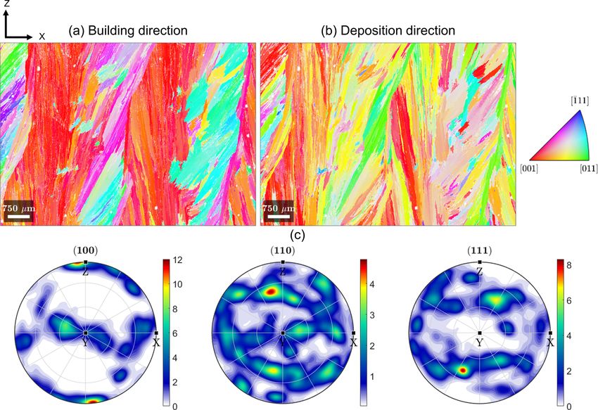
L. Palmeira Belotti et al. Journal of Materials Processing Tech. 299 (2022) 117373
by Gardner et al. (2020) at different scales, and their results allowed the with vermicular and lathy morphologies and σ-sigma intermetallic
bridge to be safely opened to the public. phases. The precipitation of the intermetallic happened mainly in the
Austenitic stainless steels are versatile metals, finding applications in interface between γ-austenite and δ-ferrite and was attributed to sub
various domains. Their broad application is owed to their excellent sequent thermal cycles reaching the σ-sigma precipitation temperature.
corrosion resistance, good processability, balanced low and high- Wang et al. (2020), who also studied thick-walled 316L parts, identified
temperature mechanical properties, and high toughness, as discussed periodically alternating structures, which they named overlapping and
by Brooks and Lippold (1993). Among the most commonly used grades remelting areas. They reported that the overlapping area consists of
in welding and AM is AISI 316L and its welding variants, such as 316LSi. large columnar grains with dominant texture aligned with the
Its microstructure consists of γ-austenite (face-centred cubic crystal building direction, whereas in the remelting area, the grains tend to be
structure) and δ-ferrite (body-centred cubic crystal structure) when perpendicular to the fusion boundary.
fabricated by casting, welding, or AM because of the processes’ inherent Although studies report the microstructural characteristics of thick
fast cooling. During these processes, the metal solidifies primarily as 316L parts, these are limited and do not provide an in-depth under
δ-ferrite, then as γ-austenite. Lippold and Savage (1982) studied the standing of the spatial variations of different microstructural features
solidification and propensity of hot cracking of austenitic stainless steels across the thick part and their correlation to the WAAM procedure.
weldments. The authors reported that the presence of δ-ferrite prevented Therefore, this research aims to provide a detailed understanding of the
hot cracking and reduced segregation in the material during processing. microstructural characteristics of WAAM 316LSi thick parts because of
However, carbides and intermetallic phases preferentially precipitate at their high relevance for producing large-scale critical structural parts
δ-ferrite and phase interfaces, locally deteriorating the corrosion resis for, e.g., marine industries. For this purpose, the structure of a thick-
tance of welded stainless steels. Sourmail (2001) and Hsieh and Wu walled part is experimentally investigated at different scales using
(2012) discussed the precipitation mechanisms of these secondary various correlative microscopy techniques to identify and understand
phases in detail. Sourmail (2001) reviewed the most common pre spatial variations in WAAM parts’ microstructure. Furthermore, a
cipitates in austenitic stainless steel. Differently, Hsieh and Wu (2012) detailed understanding of the microstructure is essential in exploiting
focused on the precipitation of the σ-sigma intermetallic phase, which the versatility that WAAM offers. For example, locally tailoring the
deteriorates the properties of the stainless steel. structure and the mechanical properties may significantly extend
The structure of 316L fabricated using WAAM consists of coarse WAAM parts’ applicability with specific requirements and applications.
columnar grain structures oriented along the direction of maximum heat
extraction, aligned with the building direction. The microstructure 2. Materials and methods
consists of γ-austenite matrix and dendritic δ-ferrite, with vermicular
(skeletal-like shape) and lathy (lath-like shape) morphologies of the 2.1. Material fabrication
latter. The formation of these morphologies has been studied in detail
for austenitic stainless steel weldments by Inoue et al. (2000). They The fabrication of the thick-walled part was performed using a
reported that lathy ferrite is formed when a crystallographic orientation Panasonic TM 2000 welding robot equipped with a Panasonic YT –
relationship is established between ferrite and austenite during solidi CET351 Active torch. The part consisted of a block of approximately 150
fication. Vermicular ferrite is formed when no crystal orientation rela mm x 40 mm x 25 mm built on a 200 mm x 100 mm x 10 mm hot-rolled
tionship is present. Many authors have reported these microstructural 316L base plate using a bidirectional scanning path as schematically
characteristics for thin-walled parts for different WAAM processing shown in Fig. 1. Each layer consisted of 10 straight and parallel weld
conditions. For example, Cunningham et al. (2019) investigated the beads stacked along the transverse direction with the same deposition
effect of heat input and interlayer cooling in the microstructure and direction. Subsequent layers were deposited with a similar stacking of
mechanical properties of thin-walled 316LSi parts. They reported peri the weld beads but with opposite deposition directions. The feedstock
odically varying grain structure, from fine to coarse grains, and micro was 1 mm diameter LNM 316LSi (AWS A5.9 grade) wire from Lincoln
structure with γ-austenite matrix and dendritic δ-ferrite with lathy and Electric with a composition presented in Table 1. This wire has higher
vermicular morphologies of the latter. Wang et al. (2019) explored the silicon content than 316L to increase the fluidity of the molten material,
effect of different arc modes in the microstructure and mechanical thus increasing weldability. The WAAM procedure was performed on a
properties of the 316L thin walls manufactured by WAAM. The authors water-cooled copper welding table under the conditions, based on
identified large columnar grains with texture and increased the RAMLAB’s expertise for processing 316LSi, summarised in Table 2. A
secondary dendrite arm spacing (SDAS) along the building direction. partial layer consisting of 5 weld beads was deposited on top of the
These microstructural gradients were attributed to decreasing cooling manufactured part, as shown in Fig. 2a and d.
rates as the layers are stacked due to the heating of previously deposited
material.
The geometry of the part also affects the thermal conditions during 2.2. Microstructure characterisation
the fabrication procedure. In thin-walled parts, the heat extraction is
dominated by conduction between the deposited material and the base Metallographic specimens in the XZ (transverse–building cross-
plate. In thick-walled parts, with multiple overlapping weld beads in section), YZ (deposition–building cross-section) and XY (trans
width, heat is also extracted by the material from the sides, next to the verse–deposition cross-section) planes are extracted from the middle of
dissipation to the baseplate. Thus, the thermal history in thick-walled the part using wire electro-discharge machining. These specimens are
parts is more complex than in thin-walled ones. Additionally, these prepared for analysis using standard metallographic procedures, which
thick parts are more challenging to build because of bead overlapping. Li consisted of mechanical grinding with SiC from 200 to 1200 grit number
et al. (2018) proposed and experimentally demonstrated a followed by mechanical polishing with 3 μm diamond suspension and
layers-overlapping strategy based on a revised layers-overlapping model 0.05 μm colloidal silica. Two different chemical reagents, based on the
to fabricate near-net-shape WAAM parts. The increase in manufacturing principles of colour metallography presented by Voort (2004), are used
complexity of thick-walled parts means that, for different materials, a to reveal the structure of the material:
comparatively limited number of studies have focused on the metallurgy
of thick parts produced by WAAM. Chen et al. (2017) studied the 1 The grain structure is revealed using a solution consisting of 300 mL
microstructure and mechanical properties of 316L manufactured by H2O, 60 mL HCl and 3 g K2O5S2, in which the specimens were
WAAM (GMAW-based). They reported grain structure aligned with the immersed in the solution for 60 s to provide enough contrast between
building direction, and microstructure consisting of γ-austenite, δ-ferrite different grains;
2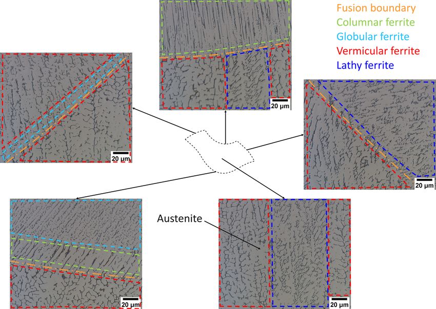
L. Palmeira Belotti et al. Journal of Materials Processing Tech. 299 (2022) 117373
Fig. 1. Schematic of the fabricated part with identified reference directions and coordinate system.
defects is studied using SEM micrographs with a 50 μm field of view at
Table 1
different positions of an XZ cross-section. The chemical composition of
Typical composition (wt%) of the LNM316LSi wire (AWS, 2017).
the different phases is studied using energy-dispersive X-ray spectros
C Mn Si Cr Ni Mo Fe copy (EDX) on an FEI Sirion SEM equipped with an EDAX Octane EDX
0.01 1.8 0.8 18.5 12.2 2.5 Bal. detector. The specimens’ texture and crystal orientation are obtained
using electron backscattered diffraction (EBSD) on a Tescan Mira3 SEM
with EDAX DigiView EBSD detector using 20 kV acceleration voltage, 30
Table 2 mm working distance, 10 μm step sizes, and 70◦ sample tilt. The EBSD
WAAM (GMAW-based) processing conditions used for manufacturing the results are analysed using the MTEX Matlab toolbox developed by
thick-walled part. Bachmann et al. (2010).
Parameters Values
3. Results
Voltage 20.5 V
Current 160 A
Wire-feed speed 8.5 m/min 3.1. Grain structure
Scanning speed 0.75 m/min
Contact tip distance 15 mm The WAAM part and overview of the grain structures of different
Interlayer temperature 150 ◦ C cross-sections are presented in Fig. 2. Here, the X-axis, Y-axis and Z-axis
Shielding gas Ar + 1% CO2 + 18% He
Shielding gas flow 20 L/min
are parallel to the transverse, deposition and building directions,
Parallel/bead spacing 3.85 mm respectively. The YZ (Fig. 2b) and XZ (Fig. 2d) cross-sections reveal a
Height/layer spacing 2.2 mm structure dominated by large and elongated columnar grains, most
Weld beads per layer 10 clearly seen in the XZ-plane. The grains are aligned with the building
Number of layers 10
direction in the centre of the part but are directed towards the sides near
the edges of the part. Besides the grain structure, the fusion lines can also
2 The different phases are revealed using an electrolytic etching pro be identified in the optical micrographs. In the YZ (Fig. 2b) and XY
cedure, consisting of a 50 g NaOH and 300 mL H2O solution with 2 V (Fig. 2c) cross-sections, the fusion lines exhibit a corrugated profile due
direct current for 10 s. to the material transfer during the manufacturing procedure. Addi
tionally, a few round macro defects are present, suggesting gas porosity,
The exposed microstructure of the specimens is analysed using op but the overall part is bulky with a low amount of defects as expected for
tical and scanning electron microscopy (SEM). An overview of the entire WAAM parts.
specimen cross-section is obtained by taking a series of micrographs The grain growth direction across the XZ plane is shown in Fig. 3 and
with a (Sensofar S Neox) optical microscope (OM) in bright-field im confirms the grain’s expected preferential alignment along the building
aging mode. Subsequently, these micrographs are stitched using the direction. Furthermore, regions with prevalent grain alignment are
Microscopy Image Stitching Tool (MIST) plugin for Fiji, developed by noticeable with a periodic trend across the part, suggesting a strong
Chalfoun et al. (2017). The overviews are used to study the grain growth influence of the tool path and processing conditions in the part’s
direction across the WAAM part by applying derivative-based post- microstructure.
processing on the optical micrographs using the open-source Ori A magnified micrograph of the XZ plane, where the fusion bound
entationJ Fiji plugin developed by Püspöki et al. (2016). This aries are visible, is presented in Fig. 4. In Fig. 4a, the fusion boundaries
open-source plugin is used to study the local orientation by taking the that define neighbouring fusion zones are highlighted. The distinct
gradient of an image and solving an optimisation problem to calculate zones exhibit a bell-shaped penetration profile, the distance the fusion
the direction that maximises the directional derivative. The fusion zones extends into the previously deposited material, resulting from the pro
are analysed using a recently developed algorithm for shape analysis and cessing parameters employed to manufacture the sample. The grains
mapping information, as described by Belotti et al. (2021). Higher tend to grow perpendicular to the fusion boundary, which is expected to
magnification micrographs are required to study different phases and correspond with the direction of maximum heat extraction. In Fig. 4b,
defects, so both OM and SEM (using Tescan Mira3 and FEI Sirion SEM) the grain growth direction is studied from the local angular map, con
were used for this analysis. The local phase content is obtained by firming the tendency of the grains to grow perpendicular to the fusion
converting the higher magnified OM micrographs (1000x) to binary interface. Moreover, strong alignment is observed in the overlapping
ones and calculating the ratio of foreground (ferrite) and background region between neighbouring fusion zones, confirming the observations
(austenite) pixels in the image using Fiji, a distribution of ImageJ pre in Fig. 3.
sented by Schindelin et al. (2012). The presence of inclusions and micro
3
L. Palmeira Belotti et al. Journal of Materials Processing Tech. 299 (2022) 117373
Fig. 2. (a) Thick-walled WAAM part along with
the adopted coordinate system. (b) Overview of
the grain structure of the YZ plane showing
coarse columnar grains aligned with the build
ing direction (parallel to Z-axis) and corrugated
fusion lines (white arrows) parallel to the
deposition direction (parallel to Y-axis). (c) The
grain structure of the XY plane showing corru
gated fusion lines (white arrows) that define
parallel weld beads along the deposition direc
tion (parallel to Y-axis) and round-shaped
macro defect (red arrow). (d) A complete
cross-section of the XZ plane’s grain structure
shows a coarse columnar grain structure across
the part and some round-shaped defects (red
arrows). (For interpretation of the references to
colour in this figure legend, the reader is
referred to the web version of this article).
Fig. 3. Map of the local angular information, corresponding to
the grain growth direction in the XZ plane, thereby revealing a
periodic trend across the WAAM part. These angles were ob
tained using the OrientationJ plugin in Fiji with a local window
of 8 pixels and a cubic spline method. The colour represents the
grain growth direction relative to the horizontal direction in
degrees, as indicated by the colour wheel. (For interpretation of
the references to colour in this figure legend, the reader is
referred to the web version of this article).
3.2. Fusion zone geometry shape of the fusion zones varies across the WAAM part, as shown in
Fig. 5c. However, the calculated mean fusion zone shape closely repre
The fusion zone’s geometry depends on the combination of the ma sents the average geometrical features of the experimental data. Inter
terial, the shielding gas, and processing conditions. Here, the fusion estingly, the average width and height of the fusion zones also closely
zones are traced from the XZ cross-section, and their geometry is studied correlate with the parallel bead spacing set value (3.85 mm) and vertical
using the mean fusion zone shape, obtained using the dedicated map layer spacing (2.2 mm) of the welding robot during the manufacturing
ping methodology presented by Belotti et al. (2021). Fig. 5a shows the process. This correlation suggests that the employed definitions of width
traced outlines of the fusion zones. The red outlines (36 fusion zones) and height of the fusion zone are adequate to study spatial variations
were used to calculate the mean shape, and the yellow ones (28 fusion across the part. In Fig. 6, the difference between each fusion zone and
zones) were added to study the spatial variations in geometrical features the mean shape in terms of area, width, height and rotation are visual
(i.e. area, width, and height). The outermost weld beads (right and left ised over the XZ-plane. In the bulk of the thick-walled part, no signifi
edges of the part) and layers (first and tenth) were not considered cant trends can be identified. However, close to the left and right edges,
because they do not represent the bulk of the thick-walled WAAM part. smaller areas of the fusion zones are found (Fig. 6a). The reduction in
The aligned outlines, the calculated mean fusion zone shape and the area is concurrent to variations in the fusion zones’ width and height, as
definition of width and height are shown in Fig. 5b. As expected, the shown in Fig. 6b and c. These geometrical variations result from uneven
4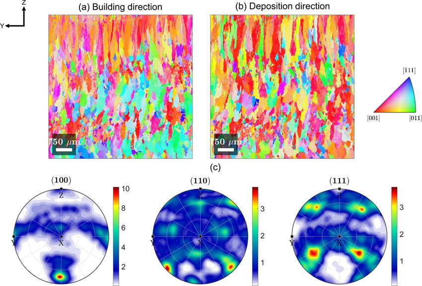
L. Palmeira Belotti et al. Journal of Materials Processing Tech. 299 (2022) 117373
Fig. 4. (a) Magnified view of an XZ cross-
section, in which the fusion boundaries (white
lines) and unique fusion zones are highlighted.
(b) Local angular information of the micro
graph confirms the grains’ tendency to grow
perpendicular to the fusion interface. Addi
tionally, the grains are prevalently aligned with
the building direction at the overlapping region
between adjacent fusion zones. The colour
represents the grain growth direction relative to
the horizontal direction in degrees, as indicated
by the colour wheel. (For interpretation of the
references to colour in this figure legend, the
reader is referred to the web version of this
article).
Fig. 5. (a) Grayscale cross-section in the XZ
plane with traced fusion zones. In total, 64
fusion zones were traced (red and yellow con
tours), from which 36 (shown in red) were used
for calculating the mean fusion zone shape. (b)
Aligned coordinates of the fusion zones and
calculated mean shape using a dedicated map
ping methodology procedure presented by
Belotti et al. (2021). The definition of fusion
zone height and width, which reflect the prin
cipal dimensions of the fusion zones, is sche
matically shown in the figure. (c) Boxplot of the
variation of area, width and height of the 64
fusion zones. The blue box ranges from the
lower (Q1 or 25th percentile) and upper (Q3 or
75th percentile) quartile of each dataset, the
red line corresponds to median (Q2 or 50th
percentile), the black whisker ranges from Q1 −
1.5(Q3 − Q1 ) to Q3 + 1.5(Q3 − Q1 ), and values
outside the whisker are considered outliers (red
crosses). (For interpretation of the references to
colour in this figure legend, the reader is
referred to the web version of this article).
layer height, which increases the contact-tip working distance and the 3.3. Solidification structure
wire resistance, thus, reducing the current and the local heat input.
Additionally, the leftmost and rightmost fusion zones are rotated The solidification structure of the WAAM part contains γ-austenite
compared to the mean one, as seen in Fig. 6d. The rotation is caused by and δ-ferrite, as empirically described by constitution diagrams such as
the part’s geometrical differences closer to the boundaries during Schaeffler (1949) and Delong (1974). The used steel, with its nominal
manufacturing due to the uneven layer height. composition shown in Table 1, primarily solidifies as δ-ferrite with a
The periodically and spatially varying grain growth directions are vermicular (skeletal-like) or lathy (lath-like) morphology depending
shown in Figs. 3 and 4b. Next, the grain growth directions inside each mainly on its alignment with the heat flow direction and the crystallo
fusion zone are mapped to the mean fusion zone shape (Fig. 5b). All this graphic orientation relationship with austenite, as previously investi
information is averaged using the mapping methodology following the gated by Inoue et al. (2000). However, the δ-ferrite morphology varies
procedure proposed by Belotti et al. (2021). The resulting average grain across the part and over a fusion zone, as shown in Fig. 8. In the bulk of
growth direction and the corresponding degree of uniformity mapped the fusion zone, the δ-ferrite exhibits mainly vermicular and lathy
inside the mean fusion zone shape are presented in Fig. 7a and b. The morphologies. However, at the fusion interface, taken as the first iden
average grain growth direction closely represents the grain growth di tifiable transition region with microstructure variation between two
rection inside the fusion zones, as noticeable from the high degree of neighbouring fusion zones, other morphologies are also present, such as
uniformity in the data. These results confirm the periodic grain structure columnar and globular structures. The variation in the δ-ferrite
across the part and grains’ tendency to grow perpendicular to the fusion morphology has been studied in the welding community. Suutala et al.
boundary. (1979) investigated the solidification and microstructure of austenitic
stainless steel welds. The authors found that the δ-ferrite morphology
depends on the composition of the weld metal. Variations in the material
5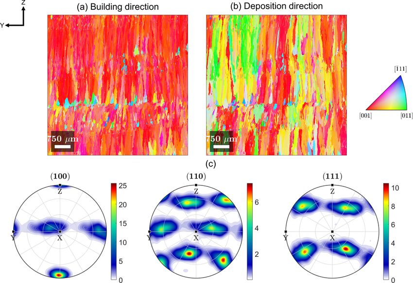
L. Palmeira Belotti et al. Journal of Materials Processing Tech. 299 (2022) 117373
Fig. 6. Variation of the fusion zones’ area (a), width (b), height (c) and rotation (d) compared to the mean fusion zone shape. A higher variation is observed in the
outermost fusion zones, close to the left and right edges, resulting from heat distribution profiles different from those in the middle. (For interpretation of the
references to colour in this figure legend, the reader is referred to the web version of this article).
Fig. 7. (a) Average grain growth direction,
obtained from all the individual grain growth
directions shown in Fig. 3, mapped inside the
mean fusion zone shape. (b) The corresponding
degree of uniformity is defined as 2D − 1,
where D is the largest eigenvalue of the local
grain growth direction, as Belotti et al. (2021)
proposed. A high degree of uniformity trans
lates into a small variability in the local grain
growth direction across all the traced fusion
zones. (For interpretation of the references to
colour in this figure legend, the reader is
referred to the web version of this article).
composition result in different solidification modes, leading to different along the building direction.
phase morphologies. David (1981) studied the variation of the δ-ferrite Besides γ-austenite and δ-ferrite, dispersed round-shaped inclusions
morphology in stainless steel multipass welds. The author reported are present in the material, as shown in Fig. 10. The nature of these
variations in the shape of δ-ferrite due to subsequent thermal cycles in particles has been identified using EDX analysis, shown in Fig. 11. The
the multipass welding procedure. In summary, the δ-ferrite morphology elemental analysis reveals that these inclusions are rich in oxygen, sili
is linked to the local material composition, cooling rate, formation con and manganese, suggesting that they are oxide impurities resulting
mechanism, and crystallographic orientation relationship with from oxygen pick-up during the part’s manufacturing.
austenite. Besides the morphology, the ferrite fraction also varies across
a fusion zone, see Fig. 9. Although the phase fraction locally varies, there
is no significant change in the average fraction (approximately 10.3 %)
6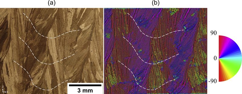
L. Palmeira Belotti et al. Journal of Materials Processing Tech. 299 (2022) 117373
Fig. 8. Local solidification structure of the part consisting of an γ-austenitic matrix and dendritic δ-ferrite. In the centre of the fusion zone, mostly vermicular and
lathy δ-ferrite are present, but columnar and globular morphologies emerge at the fusion boundaries. (For interpretation of the references to colour in this figure
legend, the reader is referred to the web version of this article).
Fig. 10. Higher magnification micrograph taken in the centre of a fusion zone,
revealing dispersed round-shaped inclusions.
expected, as is the easy-growth direction (EGD) for cubic crystal
Fig. 9. Ferrite fraction on the 1st, 5th, and 9th layers of the WAAM part, structures, as discussed in the solidification theory book by Rappaz and
showing no significant differences along the building direction. The boxplot is Dantzig (2009), and the EGD should be aligned with the direction of the
explained in the caption of Fig. 5c. maximum temperature gradient, which aligns with the building direc
tion. This alignment is most pronounced in the overlapping region be
3.4. Texture tween neighbouring fusion zones. Consequently, large columnar grains
are present in this area. The pole figures, shown in Fig. 12c, also confirm
Additively manufactured parts often result in highly oriented struc the strongly textured material with a dominant orientation in
tures, as shown in Fig. 3. The preferred orientation is also visible in the building direction.
terms of crystal orientation or texture. Fig. 12 shows the γ-austenite Although the bulk structure has a dominant texture along the
crystal orientation map with the building (Fig. 12a) and deposition building direction, it spatially varies across the transverse direction of
(Fig. 12b) direction, respectively. A preferred orientation with the the WAAM part. It was shown in Fig. 3 that the grains tend to grow
directions along the building direction is present. This is
7
L. Palmeira Belotti et al. Journal of Materials Processing Tech. 299 (2022) 117373
Fig. 11. Chemical characterisation maps obtained with EDX analysis showing the different chemical compositions of γ-austenite (Ni-rich) and δ-ferrite (Cr-rich).
Additionally, the maps also reveal that the inclusions are rich in oxygen, silicon, and manganese. The top left image shows the SEM secondary electron image with
inclusions visible as dark spots. (For interpretation of the references to colour in this figure legend, the reader is referred to the web version of this article).
Fig. 12. Austenite crystal orientation maps of the XZ plane presented as inverse pole figure (IPF) maps showing the crystallographic direction corresponding to the
building direction (a) and deposition direction (b); the colours represent the crystal orientations, as indicated by the colour scale on the right. (c) (100), (110) and
(111) pole figures related to the austenite phase showing a strong texture aligned with the building direction. (For interpretation of the references to colour in this
figure legend, the reader is referred to the web version of this article).
perpendicular to the fusion interface and that close to the edges of the with respect to the building direction can be noticed. This texture
part, the grains are directed towards the edges of the sample due to a rotation is attributed to different fusion zone shapes at the side faces of
different heat extraction direction and fusion zone shapes. In terms of the part, which are rotated compared to the ones in the centre (Fig. 6d),
texture, this spatial variability is emphasised in Fig. 13. A periodically indicating that the direction of the temperature gradient has rotated
repeating texture with dominant directions aligned with the accordingly. The rotation and change in the temperature gradient di
building direction is present in the overlapping region, followed by rection result from the uneven layer height, which translates into the
directions perpendicular to the fusion interface in the centre of edge weld beads being deposited on a curved surface.
the fusion zone. Towards the edges, a 30 ◦ rotation of the texture A YZ (deposition-building direction) cross-section was analysed in
8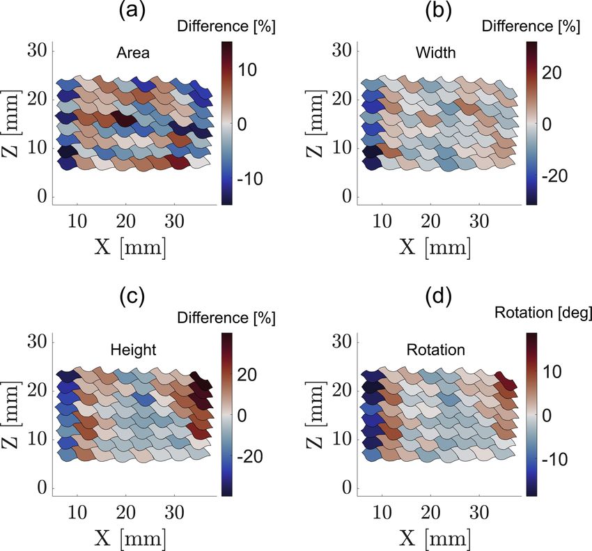
L. Palmeira Belotti et al. Journal of Materials Processing Tech. 299 (2022) 117373
Fig. 13. Spatial variation of the orientation across a WAAM part. The orientation maps and (100) pole figures were taken at four regions of the part along the
transverse direction, from the bulk (red) to the boundary (yellow) of the part. (For interpretation of the references to colour in this figure legend, the reader is
referred to the web version of this article).
terms of texture, shown in Fig. 14. Similar to the XZ plane, a dominant multidirectional. This complex thermal history depends on the combi
orientation of along the building direction is clearly visible in nation of processing conditions, such as tool path design, heat input,
the IPF maps in Fig. 14a and b. The pole figures, Fig. 14c, confirm the shielding gas, the geometry of the part, and material. The combination
strong texture along the building direction, and together with the of all the aspects mentioned above affects the structure and, conse
vertically elongated grains, suggest that this particular analysed YZ quently, are also expected to affect the mechanical properties of thick
cross-section passes through the overlapping region of fusion zones. This WAAM parts.
suggestion is enhanced when analysing another YZ cross-section in the It has been widely reported that many AM processes result in an
centre of the fusion zones, shown in Fig. 15. The IPFs (Fig. 15a and b) oriented and relatively coarse microstructure compared to traditional
show less elongated and textured grains parallel to the building direc manufacturing processes, as shown in the reviews by Collins et al.
tion. Compared to the cross-section presented in Fig. 14, the (2016) and DebRoy et al. (2018). As seen in Figs. 2d and 3, the structure
texture is slightly rotated towards the X-axis (parallel to the transverse is formed by large and oriented grains. Near the fusion boundary, the
direction), as highlighted by the pole figures in Fig. 15c. These identified structure is dominated by epitaxial growth, which means that
spatial differences result from various aspects, such as variations in the pre-existing grains act as substrate, and crystals with similar crystallo
weld bead (parallel) and layer (vertical) stacking and the cross-section graphic orientations nucleate from the molten material, as discussed by
position relative to the fusion zone shape. The grains in the over Kou (2003), who compiled the key aspects of welding metallurgy for
lapping region are elongated along the building direction, and the cross- metallic materials for the different fusion welding processes. Epitaxial
section presented in Fig. 14 clearly reveals this. The finer and less growth is clearly identified in optical micrographs (Fig. 4a) and crystal
textured structure shown in Fig. 15 suggests that the grains were not orientation maps (Fig. 12a and b). The coarse and elongated grains
sectioned along their longest axis, which is the case for the central region result from the preferred growth direction aligned with the temperature
of the fusion zones. Besides the preference of directions along gradient, which tends to be perpendicular to the fusion boundary. Each
the building direction, a weaker texture along the deposition crystal structure has an energetically favourable direction of growth, i.e.
direction is identified in Figs. 14c and 15 c. This preferred texture arises for face-centred cubic and body-centred cubic structures, which,
from the directional solidification of the molten material following the when aligned with the temperature gradient, promotes the growth of
deposition direction. those grains. The described mechanism is known as competitive growth
and dominates the grain structure away from the fusion boundary. These
4. Discussion two solidification mechanisms dominate the structure of thin or
thick-walled additively manufactured parts. Therefore, highly oriented
Thin-walled 316LSi WAAM parts have been analysed extensively. and textured structures are mostly reported, which translates into an
However, thick parts have received much less attention. The thermal anisotropic mechanical behaviour, as shown experimentally for 316L
history of block samples is complex since the material is repeatedly steel thin walls by Cunningham et al. (2019), and Wang et al. (2019),
heated and cooled at high rates, and the heat extraction is and for thick walls by Chen et al. (2017) and Wang et al. (2020).
9L. Palmeira Belotti et al. Journal of Materials Processing Tech. 299 (2022) 117373
Fig. 14. IPFs with respect to the building direction (a) and deposition direction (b) for the YZ plane in the overlapping region. The colours represent the crystal
orientations, as shown by the colour scale. (c) (100), (110) and (111) pole figures related to the austenite phase showing a strong texture aligned with the building
direction. (For interpretation of the references to colour in this figure legend, the reader is referred to the web version of this article).
Fig. 15. IPFs with respect to the building direction (a) and deposition direction (b), and corresponding (100), (110) and (111) pole figures (c) for the YZ plane in the
centre of the fusion zones. The colours represent the crystal orientations, as shown by the colour scale. (For interpretation of the references to colour in this figure
legend, the reader is referred to the web version of this article).
10L. Palmeira Belotti et al. Journal of Materials Processing Tech. 299 (2022) 117373
Recently, this anisotropic mechanical behaviour, in terms of engineering dependent strain localisation when loaded in specific directions because
yield stress, has also been numerically demonstrated using crystal of the periodic structure, as also reported by Wang et al. (2020). Thus,
plasticity finite element simulations by Van Nuland et al. (2021). the grain structure, i.e. refinement, should be tailored by modifying the
Similar metallurgical characteristics have also been reported for manufacturing conditions to prevent excessive grain growth. Cunning
other austenitic stainless steels, such as 304L. Laghi et al. (2020) per ham et al. (2018) reviewed different strategies to increase the quality of
formed microstructural and mechanical characterisation of 304L thin the WAAM parts in terms of phases, grain refinement, residual stresses,
walls manufactured by WAAM. They analysed three sets of specimens, and thermal-based inhomogeneities. For example, employing different
one extracted along the building direction (vertical), one along the shielding gases and applying the weaving motion of the welding torch
deposition direction (horizontal), and another extracted at 45◦ from the allows for changing the fusion zone’s penetration profile and, conse
deposition direction (diagonal). Their results showed an oriented quently, the grain structure. Also, altering the weld bead and layer
structure, and anisotropic elastic and plastic mechanical properties, with stacking by changing the deposition strategy and the volumetric heat
the diagonal and vertical specimens showing the highest and lowest input may allow locally refining the grain structure. These are a few
properties in both regimes, respectively. Kyvelou et al. (2020) studied possibilities for tailoring the grain structure, which will be explored in
the same material and reported similar metallurgical features. They future work.
attributed the higher stiffness for the diagonal samples to a The part’s microstructure comprises more than just the grain struc
texture, whereas the vertical and horizontal samples exhibited a domi ture, as shown in Figs. 8 and 10. γ-austenite and δ-ferrite were the two
nant texture. The anisotropy in the yield and ultimate tensile major phases identified in the material, which agrees with expectations
stresses were attributed to differences in the mean free path for dislo from the welding metallurgy of stainless steels presented by Lippold and
cations to travel for specimens sampled in different directions. Laghi Kotecki (2015). The microstructure results from the primary solidifica
et al. (2021) recently extended their work on elastic anisotropy by tion structure (γ-austenite or δ-ferrite) and post-solidification phase
introducing an experimentally validated orthotropic elastic model for transformations. The material’s chemical composition defines the pri
the same material. They reported that the specimens extracted at mary solidification structure, and the phase transformations are affected
different orientations had distinct preferred textures, with a vertical by cooling rates and subsequent reheating steps. The morphology of the
specimen with a preferred texture, a horizontal one exhibiting δ-ferrite depends on both the solidification and post-solidification
and textures, and the diagonal specimen having transformations, with vermicular and lathy being the most common
preferred a texture. These textures were used to explain the for austenitic stainless steels. However, as seen in Fig. 8, the δ-ferrite
anisotropy in the stiffness, where the specimen at 45 ◦ and the one morphology locally varies across a fusion zone, from cellular and glob
aligned with the building direction showed the highest and lowest ular morphologies at the fusion interface, to vermicular and lathy
stiffness, respectively. morphologies in the centre. These variations are a result of local cooling
The manufacturing conditions, i.e. scanning strategy, power, travel rates, chemical composition, subsequent thermal cycles, and the crys
speed and shielding gas, may lead to a different microstructure. For tallographic orientation relationship between γ-austenite and δ-ferrite,
example, the shape of the fusion zones may be different (Fig. 6), and as reported by Suutala et al. (1979), David (1981) and Inoue et al.
consequently, the solidification structure will follow (Figs. 2d and 13). (2000). These morphologies periodically repeat for unique fusion zones
Near the edges, the fusion zones are rotated (Fig. 6d), which results in across the WAAM samples, in agreement with what has been reported
grains growing towards the WAAM part’s sides (Fig. 3). Additionally, for thin parts by Cunningham et al. (2019) and Wang et al. (2019), and
the periodic stacking of the weld beads (parallel) and layers (vertical) thick parts by Chen et al. (2017) and Wang et al. (2020), for different
affects the part’s microstructure. Regions with coarse grains aligned processing conditions. The variations in the morphology are followed by
with the building direction are periodically found at the overlapping local variations in the ferrite content, but the overall ferrite fraction
regions between adjacent fusion zones (Fig. 7). These regions promote (approximately 10.3 %) is not significantly affected (Fig. 9).
unhindered grain growth, resulting in grains that are several millimetres As reported in Fig. 10, fine and dispersed oxide inclusions have also
long (Fig. 2b and d) with a preferred texture along the building been identified besides γ-austenite and δ-ferrite. The inclusions are
direction (Figs. 12 and 13). On the other hand, excessive grain growth is caused by the presence of oxygen in the melt pool during the additive
prevented in the fusion zone’s bulk. This spatially varying granular manufacturing process. Oxygen may be picked up due to improper
structure results from variations in the fusion boundary profile (Fig. 7a), shielding during fabrication, i.e. welding torch moves away as the part is
affecting the competitive growth along the part. When the profile ex exposed to a mixture of air and shielding gas. In addition, employing
hibits a negative curvature (centre of the fusion zone), excessive shielding gases and wires with oxygen in their composition may pro
competitive growth is prevented because the grains tend to grow to mote the formation of oxides during the solidification of the molten
wards the same point. Differently, when the curvature is positive material, as has been discussed for stainless steel weldments by Folkhard
(overlapping regions), grains can grow effortlessly, as shown in Figs. 7 (1988). An oxide layer forms on top of the deposited material, which can
and 12. These distinct and periodic structural characteristics agree with be mixed with the melt pool during the deposition of the subsequent
what has been reported by Wang et al. (2020). The authors reported that material layer if the oxide layer is not properly removed. Although
these periodic structural characteristics translate into anisotropic me promoting the formation of oxide inclusions, shielding gases with small
chanical properties at different loading directions. An anisotropic me additions of carbon dioxide, like the one used in this work, are used to
chanical response is expected in both elastic and plastic regimes. The stabilise the manufacturing process, increase the welding speed, and
presence of the periodic structure may lead to a spatially dependent improve the weld bead geometry, as reported for GMAW by Mvola and
local stiffness related to the material’s local texture depending on the Kah (2017) and Kou (2003). The elemental characterisation (Fig. 11)
loading conditions. For instance, the overlapping region may exhibit a reveals that the inclusions are, besides oxygen, rich in silicon and
low stiffness due to the dominant texture aligned with the manganese. These two elements are known to be strong deoxidisers and
building direction, whereas the centre of the fusion zone has a high are commonly used for reducing the amount of oxygen in the melt pool,
stiffness because of the spatially varying texture following the penetra as discussed in the welding metallurgy book by Folkhard (1988). These
tion profile of the fusion zone. In terms of anisotropy in the plastic oxide inclusions are very brittle and could act as crack initiation sites
regime, the spatial dependence of the texture and macroscopic yield when mechanically loaded, as reported by Wang et al. (2020, 2019).
stress has been studied by Van Nuland et al. (2021). They reported that The grain structure is dominated by epitaxial and competitive
the spatial location of a preferred texture, i.e. as identified in the over growth in both thin and thick WAAM parts, resulting in coarse columnar
lapping regions, prominently influences the macroscopic yield stress. grains with strong texture. In addition, similar phases have been re
The material may exhibit unstable plastic behaviour due to spatially ported, showing periodic repeatability in terms of morphology and
11L. Palmeira Belotti et al. Journal of Materials Processing Tech. 299 (2022) 117373
phase fraction. However, thick parts have a more complex microstruc References
ture by having periodic patterns related to the fusion zone shapes, grain
structure, and texture. This periodic repeatability results in parts with ASTM International, 2016. Standard guide for directed energy deposition of metals.
ASTM Stand., pp. 1–22. https://doi.org/10.1520/F3187.
spatial variations in their microstructural features linked to their pro AWS, 2017. Specification for Bare Stainless Steel Welding Electrodes and Rods. AWS.
cessing conditions and tool-path strategy. Bachmann, F., Hielscher, R., Schaeben, H., 2010. Texture analysis with MTEX- Free and
open source software toolbox. Solid State Phenom. 160, 63–68. https://doi.org/
10.4028/www.scientific.net/SSP.160.63.
5. Conclusions Belotti, L.P., Hoefnagels, J.P.M., Geers, M.G.D., van Dommelen, J.A.W., 2021. A Method
for Extracting Average Microstructure Cells From Micrographs of Additively
In this study, the microstructure of a stainless steel 316LSi thick wall Manufactured Parts. In preparation.
Brooks, J.A., Lippold, J.C., 1993. Selection of wrough austenitic stainless steels. ASM
additively manufactured part using Wire Arc AM (GMAW-based) was Handbook Volume 6: Welding, Brazing and Soldering. ASM International, p. 1299.
discussed. The conclusions from the study are summarised as: Chalfoun, J., Majurski, M., Blattner, T., Bhadriraju, K., Keyrouz, W., Bajcsy, P., Brady, M.,
2017. MIST: accurate and scalable microscopy image stitching tool with stage
modeling and error minimization. Sci. Rep. 7, 1–10. https://doi.org/10.1038/
1 The WAAM part exhibits a periodic fusion zone and granular struc
s41598-017-04567-y.
ture. In the overlapping region between neighbouring fusion zones, Chen, X., Li, J., Cheng, X., He, B., Wang, H., Huang, Z., 2017. Microstructure and
coarse and highly oriented grains and a dominant texture mechanical properties of the austenitic stainless steel 316L fabricated by gas metal
along the building direction are present due to uncontrolled arc additive manufacturing. Mater. Sci. Eng. A 703, 567–577. https://doi.org/
10.1016/J.MSEA.2017.05.024.
competitive growth. In the centre of the fusion zone, the grain Collins, P.C., Brice, D.A., Samimi, P., Ghamarian, I., Fraser, H.L., 2016. Microstructural
structure is more refined, and the crystal direction is mainly control of additively manufactured metallic materials. Annu. Rev. Mater. Res. 46,
perpendicular to the fusion boundary. 63–91. https://doi.org/10.1146/annurev-matsci-070115-031816.
Cunningham, C.R., Flynn, J.M., Shokrani, A., Dhokia, V., Newman, S.T., 2018. Invited
2 The microstructure consists of austenite, ferrite, and fine oxide in review article: strategies and processes for high quality wire arc additive
clusions. The ferrite morphology locally varies across a single fusion manufacturing. Addit. Manuf. 22, 672–686. https://doi.org/10.1016/j.
zone, exhibiting mostly cellular and globular morphologies at the addma.2018.06.020.
Cunningham, C.R., Wang, J., Dhokia, V., Shrokani, A., Newman, S.T., 2019.
fusion interface and vermicular and lathy in the centre. This spatial Characterisation of austenitic 316LSi stainless steel produced by wire arc additive
variation translates into changes in the local fraction of ferrite. manufacturing with interlayer cooling. Proceedings of the 30th Annual International
Similar variations are identified in different fusion zones, with pe Solid Freeform Fabrication Symposium – An Additive Manufacturing Conference.
David, S.A., 1981. Ferrite morphology and variations in ferrite content in austenitic
riodic repeatability of the morphology and small ferrite fraction stainless steel welds. Suppl. Weld. J. 63–71. April.
variations along the building direction. DebRoy, T., Wei, H.L., Zuback, J.S., Mukherjee, T., Elmer, J.W., Milewski, J.O., Beese, A.
3 Remarkable spatial variations in the part’s structure are present due M., Wilson-Heid, A., De, A., Zhang, W., 2018. Additive manufacturing of metallic
components – process, structure and properties. Prog. Mater. Sci. 92, 112–224.
to the additive manufacturing procedure. These variations are
https://doi.org/10.1016/j.pmatsci.2017.10.001.
identified in terms of fusion zone shape, granular structure, texture Delong, W.T., 1974. Ferrite in austenitic stainless steel weld metal. Weld. J. 53,
and phases present. 273s–286s.
Ding, D., Pan, Z., Cuiuri, D., Li, H., 2015. Wire-feed additive manufacturing of metal
components: technologies, developments and future interests. Int. J. Adv. Manuf.
By controlling the characteristics of the periodic microstructure and Technol. 81, 465–481. https://doi.org/10.1007/s00170-015-7077-3.
spatial variability through the AM processing conditions and the Folkhard, E., 1988. Welding Metallurgy of Stainless Steels. Springer, Vienna, Vienna.
building strategy, the built part’s orientation-dependent mechanical https://doi.org/10.1007/978-3-7091-8965-8.
Gardner, L., Kyvelou, P., Herbert, G., Buchanan, C., 2020. Testing and initial verification
properties can be controlled in the future. of the world’s first metal 3D printed bridge. J. Constr. Steel Res. 172, 106233
https://doi.org/10.1016/J.JCSR.2020.106233.
CRediT authorship contribution statement Greer, C., Nycz, A., Noakes, M., Richardson, B., Post, B., Kurfess, T., Love, L., 2019.
Introduction to the design rules for metal big area additive manufacturing. Addit.
Manuf. 27, 159–166. https://doi.org/10.1016/J.ADDMA.2019.02.016.
L. Palmeira Belotti: Conceptualization, Data curation, Formal Hsieh, C.-C., Wu, W., 2012. Overview of intermetallic sigma phase precipitation in
analysis, Investigation, Methodology, Software, Validation, Visualiza stainless steels. ISRN Metall. 2012, 1–16. https://doi.org/10.5402/2012/732471.
Inoue, H., Koseki, T., Ohkita, S., Fuji, M., 2000. Formation mechanism of vermicular and
tion, Writing - original draft. J.A.W. van Dommelen: Conceptualiza lacy ferrite in austenitic stainless steel weld metals. Sci. Technol. Weld. Join. 5,
tion, Funding acquisition, Methodology, Resources, Project 385–396. https://doi.org/10.1179/136217100101538452.
administration, Supervision, Writing - review & editing. M.G.D. Geers: ISO/ASTM International, 2015. Standard Terminology for Additive
Manufacturing—General Principles—Terminology. ISO/ASTM.
Conceptualization, Funding acquisition, Methodology, Resources, Proj
Kou, S., 2003. Welding Metallurgy, 2nd ed. John Wiley & Sons. 2003.
ect administration, Supervision, Writing - review & editing. C. Goulas: Kyvelou, P., Slack, H., Daskalaki Mountanou, D., Wadee, M.A., Britton, T.Ben,
Investigation, Methodology, Writing - review & editing. W. Ya: Inves Buchanan, C., Gardner, L., 2020. Mechanical and microstructural testing of wire and
arc additively manufactured sheet material. Mater. Des. 192, 108675 https://doi.
tigation, Methodology, Resources, Writing - review & editing. J.P.M.
org/10.1016/j.matdes.2020.108675.
Hoefnagels: Conceptualization, Funding acquisition, Methodology, Laghi, V., Palermo, M., Tonelli, L., Gasparini, G., Ceschini, L., Trombetti, T., 2020.
Resources, Supervision, Writing - review & editing. Tensile properties and microstructural features of 304L austenitic stainless steel
produced by wire-and-arc additive manufacturing. Int. J. Adv. Manuf. Technol. 106,
3693–3705. https://doi.org/10.1007/s00170-019-04868-8.
Declaration of Competing Interest Laghi, V., Tonelli, L., Palermo, M., Bruggi, M., Sola, R., Ceschini, L., Trombetti, T., 2021.
Experimentally-validated orthotropic elastic model for wire-and-arc additively
The authors declare that they have no known competing financial manufactured stainless steel. Addit. Manuf. 42, 101999 https://doi.org/10.1016/j.
addma.2021.101999.
interests or personal relationships that could have appeared to influence Li, Y., Han, Q., Zhang, G., Horváth, I., 2018. A layers-overlapping strategy for robotic
the work reported in this paper. wire and arc additive manufacturing of multi-layer multi-bead components with
homogeneous layers. Int. J. Adv. Manuf. Technol. 96, 3331–3344. https://doi.org/
10.1007/s00170-018-1786-3.
Acknowledgements Lippold, J.C., Kotecki, D.J., 2015. Welding metallurgy of stainless steels. Weld. Eng.
https://doi.org/10.1002/9781119191407.ch11.
This research was carried out under project number P16-46/ Lippold, J.C., Savage, V.F., 1982. Solidification of Austenitic stainless steel weldments:
part III-the effect of solidification behavior on hot cracking susceptibility the
S17024f, which is part of the Aim2XL program, in the framework of formation of a low-melting eutectic and S and P segregation along fusion zone grain
the Partnership Program of the Materials innovation institute M2i (www boundaries promotes the formation. Weld. J. 61, 388–396.
.m2i.nl) and the Netherlands Organization for Scientific Research (www Michel, F., Lockett, H., Ding, J., Martina, F., Marinelli, G., Williams, S., 2019. A modular
path planning solution for Wire + Arc Additive Manufacturing. Robot. Comput.
.nwo.nl). The research was conducted in collaboration with industrial
Integr. Manuf. 60, 1–11. https://doi.org/10.1016/J.RCIM.2019.05.009.
partners and supported by the Rotterdam Fieldlab Additive Milewski, J.O., 2017. Additive Manufacturing of Metals. Springer. https://doi.org/
Manufacturing BV (RAMLAB), www.ramlab.com. 10.1007/978-3-319-58205-4.
12You can also read