NanoPower Deployable Solar Panel Datasheet - Deployable solar panel for 3U or 6U satellite - GOMspace
←
→
Page content transcription
If your browser does not render page correctly, please read the page content below
Datasheet NanoPower DSP
 08 April 2021
 DS 1018088 2.0

 NanoPower
 Deployable Solar Panel

 Datasheet
 Deployable solar panel for 3U or 6U satellite

© 2021 GomSpace A/S                              4
Datasheet NanoPower DSP
   08 April 2021
   DS 1018088 2.0

   Product name: NanoPower DSP

   Document No.: 1018088

   Revision: 2.0

   Author: KAME / JBJ

   Reviewed by: BGS / FCO

   Approved by: LBH

   Approval date: 03-02-2021 LBH

   Confidentiality Notice
   This document is submitted for a specific purpose as agreed in writing and contains information,
   which is confidential and proprietary. The recipient agrees by accepting this document, that this
   material will not be used, transferred, reproduced, modified, copied or disclosed in whole or in
   part, in any manner or to any third party, except own staff to meet the purpose for which it was
   submitted without prior written consent.

   GomSpace © 2021

© 2021 GomSpace A/S          All printed copies, and all electronic copies and versions except the one accessible on   2
                             the GomSpace A/S server, are considered uncontrolled copies used for reference only .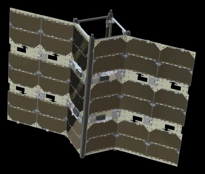
Datasheet NanoPower DSP
     08 April 2021
     DS 1018088 2.0

 1 Table of Contents
 2         OVERVIEW ............................................................................................................................................... 5
           2.1   Highlighted Features .................................................................................................................... 5
 3         WARNINGS............................................................................................................................................... 6
 4         GRAPHICAL OVERVIEW ......................................................................................................................... 7
 5         BLOCK DIAGRAM ................................................................................................................................... 8
 6         MODULE DESCRIPTION. ...................................................................................................................... 10
           6.1   Dualcell ...................................................................................................................................... 10
           6.2   Gomspace Sensor System Bus module (GSSB) ...................................................................... 10
           6.2.1 J2 – GSSB IN ............................................................................................................................ 11
           6.2.2 J3 – GSSB OUT ........................................................................................................................ 11
           6.3   P2C module ............................................................................................................................... 11
           6.3.1 J1 and J2 – Connector pinout. ................................................................................................... 11
           6.4   Interstage (Release controller) .................................................................................................. 12
           6.4.1 J103 – Connector to Deploy Burn PCB ..................................................................................... 12
           6.4.2 P1 - Programming ...................................................................................................................... 13
           6.4.3 J101 and J102 – GSSB Serial Connector (Gomspace Sensor Satellite Bus) ........................... 13
           6.4.4 J105 Cross burn function ........................................................................................................... 13
 7         BURN PCB.............................................................................................................................................. 14
 8         DEPLOYABLE SOLAR PANEL (DSP) .................................................................................................. 14
 9         MOUNTING DESCRIPTION ................................................................................................................... 16
           9.1  Mounting examples .................................................................................................................... 16
 10        HARDWARE LAYOUT ........................................................................................................................... 17
           10.1 Connectors................................................................................................................................. 17
 11        COARSE SUN SENSOR AND TEMPERATURE SENSOR .................................................................. 18
 12        FINE SUN SENSOR ON THE 135O VERSION ....................................................................................... 18
 13        RELEASE MECHANISM ........................................................................................................................ 19
 14        REDUNDANCY RELEASE SYSTEM ..................................................................................................... 20
 15        ABSOLUTE MAXIMUM RATINGS ......................................................................................................... 20
           15.1 Electrical Characteristics ........................................................................................................... 20
           15.2 Physical Characteristics ............................................................................................................. 21
 16        MECHANICAL DRAWINGS ................................................................................................................... 22
           16.1 90 o and 135 o Reverse Stowed .................................................................................................. 22
           16.2 90 o Deployed ............................................................................................................................. 23
           16.3 135 o Reverse Deployed ............................................................................................................ 24
           16.4 135 o Stowed .............................................................................................................................. 25
           16.5 135o Deployed ............................................................................................................................ 26
 17        APPENDIX .............................................................................................................................................. 27
           17.1 Solar cells in serial connection (S2C) ........................................................................................ 27
           17.2 Solar cells in parallel connection (P2C) ..................................................................................... 27
 18        DISCLAIMER .......................................................................................................................................... 28

© 2021 GomSpace A/S                         All printed copies, and all electronic copies and versions except the one accessible on                                     3
                                            the GomSpace A/S server, are considered uncontrolled copies used for reference only .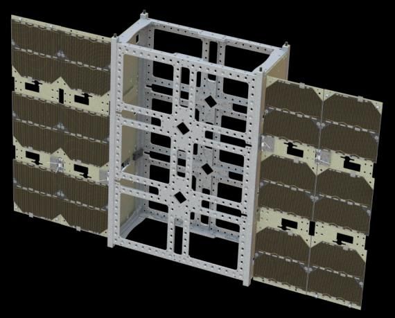
Datasheet NanoPower DSP
   08 April 2021
   DS 1018088 2.0

 Document Change Log (Not mandatory)
    Revision        Date         Name           Description
    2.0             04-02-2020   KAME           Released version 2.
    2.5             08-04-2021   KAME           Added description about J105

© 2021 GomSpace A/S              All printed copies, and all electronic copies and versions except the one accessible on   4
                                 the GomSpace A/S server, are considered uncontrolled copies used for reference only .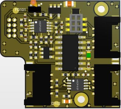
Datasheet NanoPower DSP
08 April 2021
DS 1018088 2.0
2 Overview
The GomSpace NanoPower Deployable Solar Panel (DSP) is designed to give maximum energy in a very low
formfactor. As Gomspace are developing nanosatellites this product is designed with this formfactor in focus.
The Deployable panel design fit on the side of a structure of minimum 3U. It is composed of three panels
connected side by side with the ability of being folded together for minimum space occupation under transport
and launch.
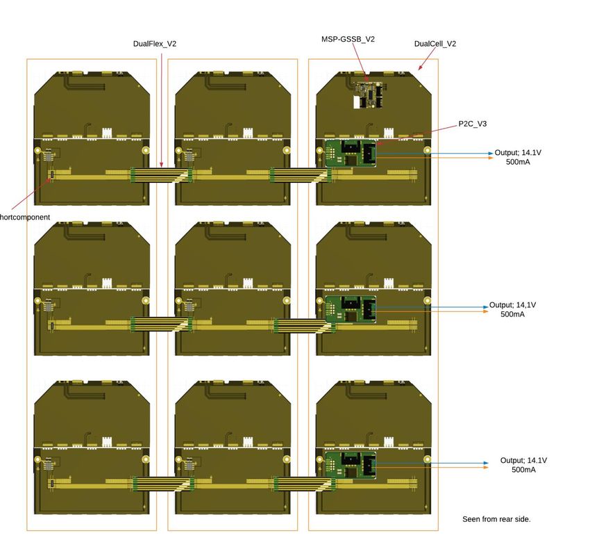
The DSP come in three versions, a 135° version, a 90° version and a 135° reverse version. The CAD below,
shows the 135° version and 90° version DSP variants. The difference between 135° reverse version and the
90° version is the angle they deploy to.
90-degree version
135-degree version
2.1 Highlighted Features
General
• 135° version; three panels with solar cells
• 90° version; two panels with solar cells
• 135° reverse; with two panels with solar cells
• Redundant panel release mechanism,
• Gomspace Sensor System Bus, GSSB connectors
• Coarse sun sensor on the 135-degree version
• External temperature sensor the 135-degree version
• The 135 o comes with two GomSpace Fine Sun Sensors.
• Operational temperature: -60°C to +80°C
Solar cells
• 30% solar panel efficiency
• Up to 1.15 W per cell in LEO
• Space qualified triple junction solar cell assemblies
• Cover glass included
• 30cm2 effective area pr. solar cell
• Cell base material: GaInP/GaAs/Ge on Ge substrate
© 2021 GomSpace A/S All printed copies, and all electronic copies and versions except the one accessible on 5
the GomSpace A/S server, are considered uncontrolled copies used for reference only .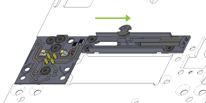
Datasheet NanoPower DSP
   08 April 2021
   DS 1018088 2.0

 3 Warnings

                    Handling
 This product uses advanced solar cells that are fragile. Do not touch solar cells.

                             Only handle solar panels without touching solar cells
                                                 or their tabs

                                         Never place anything on solar cells!

                    ESD
 This product uses semiconductors that can be damaged by electrostatic discharge (ESD). When handling,
 care must be taken so that the devices are not damaged. Use appropriate precautions.

© 2021 GomSpace A/S               All printed copies, and all electronic copies and versions except the one accessible on   6
                                 the GomSpace A/S server, are considered uncontrolled copies used for reference only .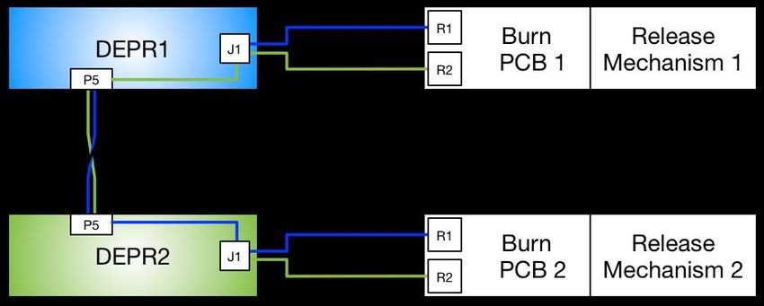
Datasheet NanoPower DSP
   08 April 2021
   DS 1018088 2.0

 4 Graphical Overview
 The illustration below labels the different parts of the DSP and illustrates how the release mechanism and the
 FSS goes through the holes in the panels in the stowed configuration. The FSS only goes through the first
 panel, and is party hidden by the last panel, hence it cannot be used until the panels are released.
 A benefit of this is the FSS can be used as deployment detection, which GomSpace have done.

© 2021 GomSpace A/S           All printed copies, and all electronic copies and versions except the one accessible on   7
                              the GomSpace A/S server, are considered uncontrolled copies used for reference only .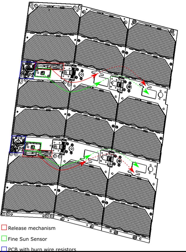
Datasheet NanoPower DSP
 08 April 2021
 DS 1018088 2.0

5 Block diagram

                                                                              Coarse    sun
                                                                              sensor.
                                                                                   GSSB
                                                                              Temperature

                                                                              sensor.

             Dualcell               Dualcell                       Dualcell

                                                                                        S2C /
                                                                                         P2C

                                                                    Release

             Dualcell               Dualcell                       Dualcell
                                                                                        S2C /
                                                                                         P2C

                           Figure 1: 135-degree Deployable Solar Panel

© 2021 GomSpace A/S                                                                             4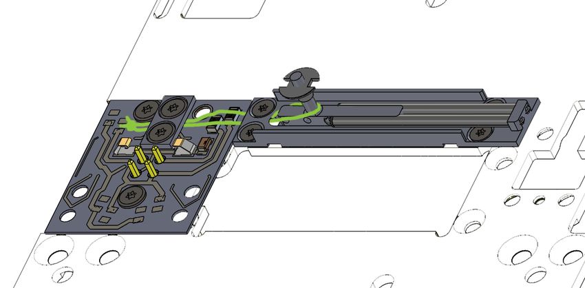
Datasheet NanoPower DSP
   08 April 2021
   DS 1018088 2.0

                                                                                                                  Coarse sun
                                                                                                                  Temperature sensor.
                                                                                                                            GSSB

                   Dualcell                                           Dualcell

                                                                                                                             S2C /
                                                                                                                              P2C

                                                                        Release

                    Dualcell                                           Dualcell
                                                                       Dualcell

                                                                                                                             S2C /
                                                                                                                              P2C

                                                                       Release

                    Dualcell                                           Dualcell
                                                                                                                             S2C /
                                                                                                                              P2C

                               Figure 2: 90-degree version and 135-degree reverse version.

© 2021 GomSpace A/S               All printed copies, and all electronic copies and versions except the one accessible on               9
                                 the GomSpace A/S server, are considered uncontrolled copies used for reference only .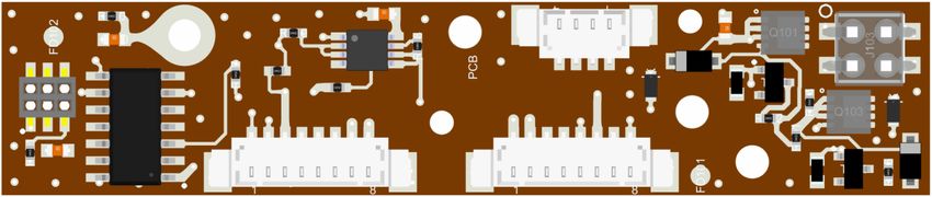
Datasheet NanoPower DSP
  08 April 2021
  DS 1018088 2.0

6 Module description.
6.1     Dualcell
The Dualcell are manufactured in 2 versions: one with bypass diodes, temperature sensor, coarse sun sensor
and connector for P2C / S2C module and one with only solar cells and bypass diodes.
The module consists mainly of a PCB mounted with 2 solar cells; these solar cells are connected in serial on
the PCB, a bypass of high quality are used to bypass the solar cell if this for one or another cause are being
damaged or stop working for some reason.

                  Dualcell

                                                                                                 Figure 3: Dualcell.

Output from one Dualcell is in best case 4.8V 2.3W (0,5A * 2.4V pr. cell). For detailed information please request datasheet.

DualCells can in the DSP panel be connected into serial strings across deployed panels, on the final
backplate “inside” the satellite it is possible to connect these strings in parallel connection or further into serial
strings. Please find an example later in this document.

6.2     Gomspace Sensor System Bus module (GSSB)
The Gomspace Sensor System Bus module are the device connecting the coarse sun sensor, CSS,
temperature device and (if exist) the fine sun sensor to the system bus.
The temperature and the coarse sun sensor signal are converted from analogue to digital signal on this board.
Communication to central processing unit is done via I2C technology, GSSB J3.

For detailed information please request datasheet.                                        Figure 4: GSSB module.

© 2021 GomSpace A/S                                                                                                             4
Datasheet NanoPower DSP
08 April 2021
DS 1018088 2.0
Connections:
6.2.1 J2 – GSSB IN
Molex Pico-Lock 1.50 mm pitch, right angle, 504050-0491.
Pin Description
1 GND
2 GSSB_SCL
3 GSSB_SDA
4 GSSB_VCC
6.2.2 J3 – GSSB OUT
Molex Pico-Lock 1.50 mm pitch, right angle, 504050-0491.
Pin Description
1 GSSB_VCC
2 GSSB_SDA
3 GSSB_SCL
4 GND
The pins on connector J2 and J3 are connected back to back. This is to avoid split harness and the sensor
bus can be routed through the GSSB module.
Communication on GSSB is I2C 3.3V level. Pull up resistors are not present on GSSB module.
6.3 P2C module
Figure 5 P2C
The P2C module can be used to connect Dualcells into a parallel connection. The implemented diode is to
secure that the current cannot be dissipated into the solar cells, can occur if more parallel strings are
connected in parallel.
6.3.1 J1 and J2 – Connector pinout.
J1 and J2 are parallel and can be used as best practice.
Pin Description
1 Cathode
2 Cathode
3 Anode
4 Anode
Molex Pico-Lock 1.50 mm pitch, right angle, 504050-0491.
Please see appendix for connection examples.
© 2021 GomSpace A/S All printed copies, and all electronic copies and versions except the one accessible on 11
the GomSpace A/S server, are considered uncontrolled copies used for reference only .Datasheet NanoPower DSP
08 April 2021
DS 1018088 2.0
6.4 Interstage (Release controller)
The Deploy Relese Controller, DEPR, is a two-part PCB, divided in a controlling part and an executing part.
The controlling part is located inside the satellite and the executing part can be placed where feasible. The
controlling part include all intelligence and communicate with the satellite system, the executing part is a
simple PCB with a few resistors for burning the wire.
Figure 6 Interstage (Release controller)
Below: PCB with straight connector.
J105
1 4 1 3
P1
J102 J101 2 4
J103
1 8 1 8
Above: PCB with angled connectors.
6.4.1 J103 – Connector to Deploy Burn PCB
Mouser 89898-302LF
In this connector the burn PCB is direct inserted.
Pin Description
1 B1_OUT
2 BURN_GND
© 2021 GomSpace A/S All printed copies, and all electronic copies and versions except the one accessible on 12
the GomSpace A/S server, are considered uncontrolled copies used for reference only .Datasheet NanoPower DSP
08 April 2021
DS 1018088 2.0
3 B2_OUT
4 Burn Release IN
6.4.2 P1 - Programming
This connector is used for internal programming of the PCB. For updating the firmware, please contact
GomSpace.
6.4.3 J101 and J102 – GSSB Serial Connector (Gomspace Sensor Satellite Bus)
Molex PicoBlade 053398-0871 or 05326-10871
The pins on connector J101 and J102 are configured to fit into the rest of the GomSpace GSSB using
products, like e.g. GomSpace Interstage GSSB.
Pin Description (J101)
1 BURN_GND
2 BURN_GND
3 BURN_B1
4 BURN_B1
5 GSSB_GND
6 GSSV_VCC
7 GSSB_SCL
8 GSSB_SDA
Pin Description (J102)
1 GSSB_SDA
2 GSSB_SCL
3 GSSB_VCC
4 GND
5 BURN_B1
6 BURN_B1
7 GND
8 GND
Burn voltage depends of the actual system design. GSSB_VCC is 3V.; I2C level is 3V3:
6.4.4 J105 Cross burn function
Mouser 538-53398-0471
This connector is used to connect 2 release controllers for obtaining the release functionality.
Pin Description
1 GND
2 BURN_POWER (input)
3 BURN_POWER (output)
4 GND
© 2021 GomSpace A/S All printed copies, and all electronic copies and versions except the one accessible on 13
the GomSpace A/S server, are considered uncontrolled copies used for reference only .Datasheet NanoPower DSP
08 April 2021
DS 1018088 2.0
7 Burn PCB
Second part of the DEPR is the burn PCB. Main function for the PCB is holding the elements used to burn the
hold wire. The PCB is used in many positions this is the reason for having 8 resistor positions; only 2 resistors
are mounted for correct burn process.
Figure 7 Burn PCB.
This PCB is direct inserted into Interstage PCB, J1 (Release controller)
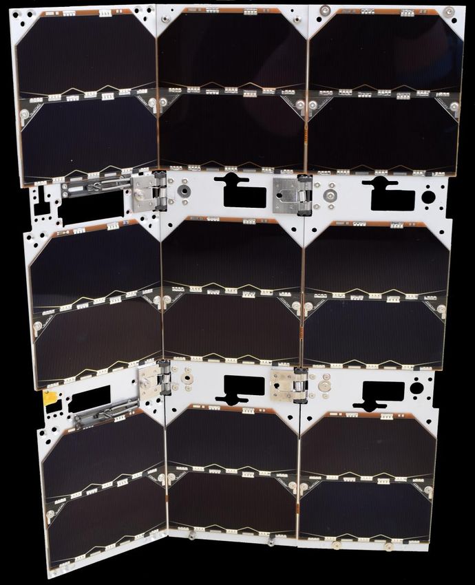
8 Deployable Solar Panel (DSP)
The following describes the 135° panel, this is the biggest and most complex and thereby also covering the
other versions.
The total panel consists of 18 solar cells combined in 3 rows of 6 cells, these rows can be configured into
serial or parallel; default is parallel.
Here below is seen a drawing of one complete deployable solar panel, 135 degree version. The panel is built
up on 3 plates (Colom’s). On every plate 3 Dual cells are placed.
From left to right: The dual cell is connected electrical to the middle via a flexible PCB, Dualflex, and again
from the middle to the right one via another Dualflex; this connects these tree Dualcells in serial. The serial
connection is in this example ending in a P2C module, this module makes it possible to connect the tree
strings output in parallel and have only one cable from the DSP to the battery pack.
The P2C can be replaced with S2C for serial connection of the tree strings.
The MSP-GSSB module are placed on the column nearest the satellite structure.
Output from the DSP module:
If the tree strings are connected in parallel the output will be (14.1V (3* 500mA)) = 14.1V 1.5A. 21.15W
If the tree strings are connected in serial the output will be ((3*14.1V) 500mA) = 42.3V 500mA. 21.15W
All calculations are for a maximum illuminated cell in beginning of solar cell life, BOL. For more specific data
for solar cell please require the data sheet.
© 2021 GomSpace A/S All printed copies, and all electronic copies and versions except the one accessible on 14
the GomSpace A/S server, are considered uncontrolled copies used for reference only .Datasheet NanoPower DSP
08 April 2021
DS 1018088 2.0
© 2021 GomSpace A/S All printed copies, and all electronic copies and versions except the one accessible on 15
the GomSpace A/S server, are considered uncontrolled copies used for reference only .Datasheet NanoPower DSP
08 April 2021
DS 1018088 2.0
9 Mounting Description
The DSP can be mounted on either a 3U or a 6U structure. The same DSP unit is designed to be installed on
either side of a structure. On a 6U structure the panels can only be mounted on the 3U sides. On a 3U
structure they can be mounted on all four 3U sides.
On the panel mounted on the body of the satellite the NanoSense Fine Sun Sensor (FSS) can be mounted,
canted 6° outwards.
9.1 Mounting examples
Below are shown different mounting configurations with both one and two DSP’s. All configurations shown are
top view of the DSP and structure. Eight configurations are shown but many more configurations can be
made.
The black squares are a symbol of solar cells.
3U Structure 6U Structure
© 2021 GomSpace A/S All printed copies, and all electronic copies and versions except the one accessible on 16
the GomSpace A/S server, are considered uncontrolled copies used for reference only .Datasheet NanoPower DSP
08 April 2021
DS 1018088 2.0
10 Hardware Layout
The panel mounted on the structure has the following connectors.
10.1 Connectors
Below is shown a drawing with the connector group names. Each of the three P2C (PCB to cable) groups are
the same and each of the DEPR (Deploy Release) and GSSB groups are the same. On the 135° version, the
FSS are mounted on the other side of the DEPR PCB. The same can be done on the 90° and 135° reverse
versions if FSS are procured separately.
The two DEPR are connected with a harness that works as a redundant panel release mechanism.
GSSB-A
P2C-A
DEPR-A
GSSB-B
P2C-B
DEPR-B
P2C-C
© 2021 GomSpace A/S All printed copies, and all electronic copies and versions except the one accessible on 17
the GomSpace A/S server, are considered uncontrolled copies used for reference only .Datasheet NanoPower DSP
08 April 2021
DS 1018088 2.0
11 Coarse Sun Sensor and Temperature Sensor
On the main panel of the 135° version are mounted a coarse sun sensor and an external temperature sensor.
Green = Temperature sensors Red = Coarse sun sensors
Two sensors are connected to the GSSB A PCB the other two sensors are connected to the GSSB B PCB,
and their readings can be accessed through the GSSBs.
12 Fine Sun Sensor on the 135o Version
The 135° Version have two NanoSense FSS mounted. The NanoSense FSS is a vector sun-sensor with an
I2C interface designed especially for CubeSats with high ADCS requirements. They are connected to the a
GSSB PCB.
Both FSSs are connected to a separate GSSB PCB.
The FSS is placed a 6° canted block directly onto the DEPR boards to prevent the 135° deployed panels to
shadow the FSS.
The FSS is not included in the 90° version and 135° reverse version due to the decreased performance.
However mounting interface for the FSS is incorporated into the DEPR board. The FSS and a GSSB module
can be bought as a standard module at GomSpace.
© 2021 GomSpace A/S All printed copies, and all electronic copies and versions except the one accessible on 18
the GomSpace A/S server, are considered uncontrolled copies used for reference only .Datasheet NanoPower DSP
08 April 2021
DS 1018088 2.0
13 Release Mechanism
By burning through a wire, a sleigh with a spring, is released. A nut and bolt mounted on the sled release the
panels which fold out by the springs in the hinge. The hinges themselves ensure correct opening angle.
Step-by-step guide of arming the release mechanism is shown in the manual.
© 2021 GomSpace A/S All printed copies, and all electronic copies and versions except the one accessible on 19
the GomSpace A/S server, are considered uncontrolled copies used for reference only .Datasheet NanoPower DSP
08 April 2021
DS 1018088 2.0
14 Redundancy Release System
The two DEPR PCBs are connected through a harness. Each burn PCB contains two burn resistors (R1 and
R2), each controlled from a different DEPR. View the illustration below.
Blue DEPR1 has access to the two R1’s and green DEPR2 has access to the two R2’s.
15 Absolute Maximum Ratings
Stresses above those listed under Absolute Maximum Rating may cause permanent damage to the DSP.
Exposure to absolute maximum rating conditions for extended periods may affect the reliability.
Symbol Description Min. Max. Unit
Top-structure Operating Temperature on the panel mounted -35 +80 °C
on the satellite body
Top-deployed Operating Temperature on the panels that are -55 +95 °C
deployed
BURN_B1 Connect to VBAT through switch on FPP* 5 32 V
* Burn resistors aligned to VBAT through option sheet
15.1 Electrical Characteristics
Parameter Condition Min Typ. Max Unit
Single Solar Panel Full sunlight in LEO
• Voltage Optimal voltage 2.32 2.42 V
• Current Current at optimal voltage 490 508 mA
• Power Maximum power 1135 1200 mW
• Efficiency 29.8 30 30.2 %
GSSB_VCC 3.3 V
GSSB_I_idle 2.6 mA
Course Sun Sensor
• Current Short current at 1367 W/m2 930 μA
• Cosine error 1.85 3.5 o
Temperature Sensor External
• Range -75 +175 oC
• Resolution 3.5 %
Temperature Sensor Internal
• Range -40 85 oC
• Resolution -10 10 %
© 2021 GomSpace A/S All printed copies, and all electronic copies and versions except the one accessible on 20
the GomSpace A/S server, are considered uncontrolled copies used for reference only .Datasheet NanoPower DSP
08 April 2021
DS 1018088 2.0
15.2 Physical Characteristics
Panels are made of AL6082 T651.
Description Typical value Unit
o o
Mass - 90 and 135 reverse 390 g
Mass - 135o 449 g
Size View Mechanical drawings in mm
chapter 16
© 2021 GomSpace A/S All printed copies, and all electronic copies and versions except the one accessible on 21
the GomSpace A/S server, are considered uncontrolled copies used for reference only .Datasheet NanoPower DSP
08 April 2021
DS 1018088 2.0
16 Mechanical Drawings
All dimensions in mm.
16.1 90 o and 135 o Reverse Stowed
© 2021 GomSpace A/S All printed copies, and all electronic copies and versions except the one accessible on 22
the GomSpace A/S server, are considered uncontrolled copies used for reference only .Datasheet NanoPower DSP
08 April 2021
DS 1018088 2.0
16.2 90 o Deployed
© 2021 GomSpace A/S All printed copies, and all electronic copies and versions except the one accessible on 23
the GomSpace A/S server, are considered uncontrolled copies used for reference only .Datasheet NanoPower DSP
08 April 2021
DS 1018088 2.0
16.3 135 o Reverse Deployed
© 2021 GomSpace A/S All printed copies, and all electronic copies and versions except the one accessible on 24
the GomSpace A/S server, are considered uncontrolled copies used for reference only .Datasheet NanoPower DSP
08 April 2021
DS 1018088 2.0
16.4 135 o Stowed
© 2021 GomSpace A/S All printed copies, and all electronic copies and versions except the one accessible on 25
the GomSpace A/S server, are considered uncontrolled copies used for reference only .Datasheet NanoPower DSP
08 April 2021
DS 1018088 2.0
16.5 135o Deployed
© 2021 GomSpace A/S All printed copies, and all electronic copies and versions except the one accessible on 26
the GomSpace A/S server, are considered uncontrolled copies used for reference only .Datasheet NanoPower DSP
08 April 2021
DS 1018088 2.0
17 Appendix
17.1 Solar cells in serial connection (S2C)
Figure 8: Drawing example of serial connected solar cells.
17.2 Solar cells in parallel connection (P2C)
Figure 9 Drawing example of parallel connected solar cells.
© 2021 GomSpace A/S All printed copies, and all electronic copies and versions except the one accessible on 27
the GomSpace A/S server, are considered uncontrolled copies used for reference only .Datasheet NanoPower DSP
08 April 2021
DS 1018088 2.0
18 Disclaimer
The information in this document is subject to change without notice and should not be construed as a
commitment by GomSpace. GomSpace assumes no responsibility for any errors that may appear in this
document.
In no event shall GomSpace be liable for incidental or consequential damages arising from use of this
document or the software and hardware described in this document.
© 2021 GomSpace A/S All printed copies, and all electronic copies and versions except the one accessible on 28
the GomSpace A/S server, are considered uncontrolled copies used for reference only .You can also read