Probabilistic Tsunami Hazard Analysis for Western Makran Coasts, Southeast Iran
←
→
Page content transcription
If your browser does not render page correctly, please read the page content below
Probabilistic Tsunami Hazard Analysis for Western Makran Coasts, Southeast Iran Hamid Zafarani International Institute of Earthquake Engineering and Seismology Leila Etemadsaeed ( etemadsaeed@iiees.ac.ir ) International Institute of Earthquake Engineering and Seismology https://orcid.org/0000-0001-9150- 0497 Mohammad Rahimi University of Tehran Navid Kheirdast International Institute of Earthquake Engineering and Seismology Amin Rashidi Savoie University: Universite Savoie Mont Blanc Yu-Lin Tsai National Central University Anooshiravan Ansari International Institute of Earthquake Engineering and Seismology Mohammad Mokhtari International Institute of Earthquake Engineering and Seismology Morteza Eskandari-Ghadi University of Tehran Research Article Keywords: Tsunami, Makran subduction zone, Probabilistic hazard analysis, Heterogeneous slip distribution, Earthquake recurrence Posted Date: February 4th, 2022 DOI: https://doi.org/10.21203/rs.3.rs-1317527/v1 License: This work is licensed under a Creative Commons Attribution 4.0 International License. Read Full License
1 Probabilistic Tsunami Hazard Analysis for Western Makran Coasts, Southeast Iran
 2
 3 Hamid Zafarani1, Leila Etemadsaeed2, Mohammad Rahimi3, Navid Kheirdast1, Amin Rashidi4
 4 Yu-Lin Tsai5, Anooshiravan Ansari1, Mohammad Mokhtari1, Morteza Eskandari-Ghadi3
 5
 6 1
 International Institute of Earthquake Engineering and Seismology (IIEES), Tehran, Iran
 7 2
 International Institute of Earthquake Engineering and Seismology (IIEES), Tehran, Iran, Etemadsaeed@iiees.ac.ir
 8 3
 School of Civil Engineering, College of Engineering, University of Tehran, Tehran, Iran
 9 4
 LAMA UMR 5127 CNRS, Université Savoie Mont Blanc, Campus Scientifique, 73376, Le Bourget-du-Lac, France
10 5
 Graduate Institute of Hydrological Oceanic Sciences, National Central University, Taoyuan City, Taiwan
11
12
13
14 Acknowledgment
15 The present study was carried out within the frame-work of the project "Tsunami and Seismic hazard assessment for
16 the Makran region." Funding for this project was provided by the Plan and Budget Organization of the Islamic
17 Republic of Iran (PBO). Our sincere thanks are due to the staff of this organization for their support: Dr. Javad Ghane-
18 fard, Eng. Ali-Reza Totonchi, and Eng. Hamid-Reza Khashei.
19
20
21
22
23
24
25
26
27
28
29
30
31
32
33
34
35
36
37
38
39
40
41
42
43
44
45
46
47
48
49

 1
50
51 Probabilistic Tsunami Hazard Analysis for Western Makran Coasts, Southeast Iran
52
53 Abstract
54 Makran subduction zone, along the southern coasts of Iran and Pakistan has a wide potential seismogenic zone and
55 may be capable of generating large magnitude (M~9) tsunamigenic earthquakes. Considering ambiguities exist in
56 tsunamigenic source characterization for subduction megathrusts like Makran, where detailed geologic, seismic, and
57 geodetic data are insufficient, the probabilistic tsunami hazard analysis (PTHA) is the most prevalent approach to
58 handle uncertainties and estimate more reliable tsunami hazard. Here, PTHA is performed for the coastal region of
59 the western Makran, southeastern Iran. Using the logic tree approach, we have considered the uncertainty of maximum
60 seismic magnitude, earthquake occurrence model, continuity of seismic zone, seismic coupling coefficient, depth of
61 rupture, presence or absence of splay faults, fault locations, and fault slip distribution in PTHA calculation for the
62 western Makran region. We have derived uniform tsunami hazard maps for two return periods of 475 and 2475 years
63 for two confidence levels, the mean and the 84th percentile. Ground subsidence effects are also evaluated in a
64 probabilistic manner. According to the PTHA results, Chabahar and Sirik towns are at the highest and lowest tsunami
65 risk, respectively.
66
67 Keywords: Tsunami, Makran subduction zone, Probabilistic hazard analysis, Heterogeneous slip distribution,
68 Earthquake recurrence
69
70 1- Introduction
71 Taking into account the catastrophic consequences of recent large magnitude (M~9) tsunami-generating
72 earthquakes (i.e., the 2004 Indian Sumatra–Andaman and the 2011 Japan Tohoku earthquakes); it is crucial to perform
73 risk analysis studies for tsunami-prone regions. The first step for a risk analysis study is to conduct a tsunami hazard
74 assessment to evaluate coastal tsunami heights from tsunamigenic source models.
75 There are two main approaches to perform a tsunami hazard assessment: deterministic and probabilistic. The
76 deterministic approach is usually conducted for a formidable scenario that can pose the largest hazard to the region of
77 interest. However, the deterministic technique might cause unanticipated errors, such as determining an inappropriate
78 worst-case scenario (i.e., underestimated or overestimated). On the other hand, from an economic point of view, the
79 assumption of a biggest or worst possible scenario might not be suitable for conventional design goals or strategies,
80 as buildings and facilities have limited lifespans. Thus, a probabilistic tsunami hazard analysis (PTHA) considering
81 in a comprehensive manner both epistemic (associated to our limited knowledge about things which are constant in
82 time) and aleatory or inherent (associated to natural variations that occur between different events) uncertainties
83 (Abrahamson and Bommer 2005) becomes a better option for a tsunami hazard assessment.
84 The Makran subduction zone (MSZ) (Fig. 1), formed by northward motion of Arabian plate beneath the Eurasia
85 plate, has a historical catalog of large earthquakes and associated tsunamis (e.g., the Makran tsunami of 1945 with
86 death toll near 4,000).
87 The MSZ is divided into two distinct segments, eastern and western Makran (Byrne et al. 1992). The eastern
88 segment hosted several historical large magnitude events at 1765, 1810 and 1945 (Ambraseys and Melville 1982), but
89 the western segment has been quiescent at least in the past 300 years. An ambiguous report of a large earthquake at
90 1483 was criticized by Musson (2009) and attributed to moderate shallow crustal earthquakes in the neighborhood
91 regions. However, the possibility of a large earthquake on the western segment or a huge event resulting from a
92 cascading rupture across two segments cannot be ruled out (Musson 2009). Penney et al. (2017), showed that the
93 subduction interface in the western Makran may be locked, accumulating elastic strain, and move in megathrust
94 earthquakes (see Frohling & Szeliga, 2016; Pajang et al., 2021), though its seismic coupling is reported to be weak
95 (Ghadimi et al. 2021, submitted).

 2
96 Recently, probabilistic tsunami hazard assessment of the MSZ has been a subject of interest for tsunami researchers
 97 and there are several PTHA for the Makran coastlines.

 98
 99 Fig. 1 Location of the MSZ and its seismicity. The pentagons show the historical earthquakes in this region. The circles show the
100 occurred earthquakes from 1900 to 2019. The radius of a circle presents the magnitude of an earthquake. The color shading
101 indicates the focal depths in km

102 A list of these studies and their specifications is summarized in Table 1. They have been conducted at different
103 scales of global, regional and local and different levels of detail were applied to describe the subduction geometry,
104 fault slip distribution and other technical factors. A major drawback of some of these studies is that the seismicity rate
105 was used instead of long-term fault slip rate to constrain the recurrence rates in the Gutenberg-Richter (GR) model
106 (see section 2-2). Moreover, they ignored the important uncertainties regarding the recurrence model or Maximum
107 magnitude and updip rupture depth.
108 The first PTHA research for Makran was conducted by Burbidge et al. (2009). They produced probabilistic tsunami
109 hazard maps for the Indian Ocean countries, including Iran, considering the effects of tsunamis generated by the
110 Makran, Sumatra–Andaman, and South Sandwich subduction zones. They presented their results as annual
111 probabilities of exceeding certain tsunami wave amplitude in the water depth of 100 m. Although not explicitly
112 mentioned, it seems that the coupling factor in this study has been taken into account with the technique in which the
113 rate of earthquake occurrence for each subduction zone is determined based on the percentage of the global subduction
114 seismicity. Activity rates for each subduction zone, defined as the fraction of the global subduction zone seismicity
115 that would be expected on each zone, was calculated based on the ratio of its length to the length of all tsunamigenic
116 subduction zones in the world. The main problem in this technique is the assumption that the coupling factor for any
117 given subduction zone is not significantly different from the global average along megathrusts In Burbidge et al.
118 (2009) study, three possible rupture areas were considered for each modeled earthquake using the empirical scaling
119 relations of Wells and Coppersmith (1994), which is not a subduction zone-specific relationship.
120 Following the study of Burbidge et al. (2009), several articles have been conducted on the PTHA in the MSZ.
121 Using a limited mixed earthquake catalog of the Makran region including shallow crustal, interface and intraplate
122 events to constrain the truncated Gutenberg-Richter (TGR) recurrence relation, Heidarzadeh and Kijko (2011) defined
123 three scenarios with identical fixed magnitude (Mw 8.1) in the eastern, central and western Makran for a probabilistic
124 tsunami hazard assessment along the coasts of Iran, Oman and Pakistan. They considered fixed magnitude, location,
125 and depth and also uniform slip distribution for each scenario.
126 Løvholt et al. (2012) conducted a tsunami hazard assessment on the global scale including the MSZ. Hoechner et
127 al. (2016) used the TGR recurrence model and Makran instrumental era catalog in computing the exceedance rate of

 3
128 tsunami height for Makran coastlines. The slip rate of the MSZ was ignored in their analysis and they used the general
129 seismicity of the whole Makran region without any distinction between shallow crustal, interface and intraplate
130 earthquakes.
131 El-Hussain et al. (2016, 2018) constructed some source models with different magnitudes along the MSZ and
132 used the logic-tree procedure and probabilistic method to estimate the tsunami hazard along the Oman shorelines.
133 They only employed the TGR recurrence model for magnitude-frequency and assumed uniform slip on earthquake
134 sources. Also, while not considering the coupling coefficient, probabilistic results were presented for the coasts of
135 Oman.
136 In another global-scale study, Davies et al. (2017) performed a probabilistic tsunami hazard assessment. They
137 assigned three slip rates of 5.4, 9.0 and 13.0 mm/year for the Makran fault. Assuming a convergence rate of 20
138 mm/year, the resulting coupling factors are about 0.3, 0.5 and 0.7. They also assumed three maximum magnitudes of
139 8.1, 8.8 and 9.5. They did not take into account the segmentation of the MSZ into the western and eastern segments.
140 Another probabilistic tsunami hazard assessment was done by Am. Rashidi et al. (2020b) for a range of
141 heterogeneous slip distributions of the MSZ. Tsunami hazard curves and probability maps for the region were their
142 outcome. They used the TGR recurrence model and a fixed non-planar geometry for the MSZ. The effect of seismic
143 coupling was not a part of their computations.
144 In general, probabilistic tsunami hazard assessment is a multidisciplinary problem which contains tsunami
145 numerical modeling and probabilistic calculations for the earthquake source and tsunami wave amplitude. This would
146 require different experts in various fields of seismology, seismotectonics, geodesy, probability and statistics, hazard
147 assessment, and numerical hydrodynamic modeling. So far, a comprehensive study using the knowledge of the above
148 various fields and combining them together in a logical and scientific format, has not been done at a regional-scale for
149 the western Makran coastline. Present study tries to resolve and address the weaknesses and limitations of the previous
150 studies as much as possible.
151 In this study, we consider the uncertainty of maximum seismic magnitude, earthquake occurrence models,
152 continuity of seismic zone, seismic coupling coefficient, depth of rupture, presence or absence of splay faults, fault
153 locations, and fault slip distribution in PTHA for the MSZ. To clarify the importance of considering these
154 uncertainties, it is worth noting that in modeling the tsunami observed after the only instrumental era large interface
155 event in this region, i.e. the 1945 Makran earthquake with a magnitude of 8.1, there are significant differences between
156 the hypotheses of various studies (e.g., Heidarzadeh et al. 2008, 2009; Jaiswal et al. 2009; Neetu et al. 2011).
157 Considering homogeneous slip model, and presence or no presence of splay faulting (reaching the rupture to the
158 seabed), are among the main reasons for the failure to model the observed tsunami wave height of this earthquake.
159 This would place another emphasis on the key role of nonhomogeneous slip distribution to have a more reliable
160 estimate of expected tsunami wave amplitudes, a factor that was ignored in most of the past PTHA studies (Table 1).
161 In addition to non-uniform slip, the present study incorporates multiple assumptions including different top depths of
162 the rupture, fault-rupture-scaling model, the effect of coupling in seismic activity of the region, and a more precise
163 bathymetry data (see sections 2). Earth subsidence effects are also evaluated in a probabilistic manner in this study for
164 the first time.
165 It should be mentioned that our study only includes earthquake scenarios from the MSZ. As shown by the
166 simulation results in Okal and Synolakis (2008), far-field scenarios have only mild effects on the Makran coasts and
167 are thus excluded from our study.
168
169 2- Uncertainties in western Makran tsunami modeling
170 There are both aleatory and epistemic uncertainties in a PTHA study, though sometimes the margin between these
171 two categories is vague and depends on personal opinion.
172 Aleatory uncertainties in fact indicate the natural randomness inherent in the nature of phenomena, whereas
173 epistemic uncertainties are due to a lack of information and human knowledge about the natural processes. The logic
174 tree is an efficient tool for considering epistemic uncertainties in probabilistic hazard and risk analysis studies, first
175 introduced to the field by Kulkarni et al. (1984). One of the most important parameters in determining the behavior

 4

176 and output of the logic tree is the weighting done by experts into its various branches, which represent different
177 hypotheses in modeling. The branch weights in a logic tree represent the degree of belief of experts in each element
178 of models.
179 In the next section, by expression the uncertainties in tsunami hazard analysis in the MSZ; the considered logic
180 tree for this study (Fig. 2) is introduced. It should be noted that, the dip-angle of the subduction interface of the MSZ
181 could be another source of uncertainty and was a matter of debate for a long time (see e.g. Byrne et al. (1992), Maggi
182 et al. (2000), Kopp et al (2000), Penny et al. (2017)). Penny et al. (2017) implemented well-located earthquakes in the
183 region, and receiver functions from local seismometers to constrain the range of possible interface dips. They reported
184 maximum average dips of ∼11◦ in the western, ∼9◦ in the central and ∼8◦ in the eastern Makran region, respectively.
185 In a recent study, using the wide-angle reflection technique along three crustal-scale, trench-perpendicular, deep
186 seismic sounding profiles, Haberland et al. (2020) has delineated the position and the dip of the subducting plate
187 (oceanic Moho). According to Haberland et al. (2020) the crustal structure and the very gentle dip (∼8° ± 2°) of the
188 subducting plate suggest a very wide contact zone, potentially allowing very wide asperities. In the light of
189 aforementioned studies, here a fixed value is used for the dip of the subduction interface which is important for
190 assessing tsunami wave height generated by different seismic scenarios.
191
192 2-1 Maximum seismic magnitude of the MSZ
193 For years, seismologists believed that some subduction zones would never be able to produce earthquakes of
194 magnitude Mw 9.0 or greater (Ruff and Kanamori 1980). However, after the 2004 Indonesia Mw 9.2 and the 2011
195 Japan Mw 9.0 earthquakes, the general view of seismologists is that all or at least most of the subduction zones are
196 capable to produce an earthquake of magnitude Mw 9.0, in a global analogy context. Generally, there are two main
197 approaches for determination of the maximum magnitude (Mmax): those that are based on an earthquake catalog
198 (maximum observed magnitude plus an increment) and those based on empirical scaling relations through a seismic
199 source zone model. The second method, in the simplest way uses fault length, while a more accurate alternative is to
200 use the rupture area (which is proportional to the accumulated moment, Hanks and Kanamori 1979). Due to lack of
201 historical events, except the 1945 Mw 8.2 earthquake in the eastern Makran, here we emphasize more on the second
202 approach, which implies adopting the concept of global analogy of Mmax for all subduction zones (Meletti et al.
203 2010). As the seismic moment released in an earthquake is a function of rupture area, so assuming an average shear
204 modulus of μ = 30 GPa for subduction zones (Hanks and Kanamori 1979), average dip angle of 8° and length of 900
205 km for the entire MSZ (or even the eastern or western segment of the MSZ), occurrence of an earthquake magnitude
206 equal to or greater than Mw 9.0 is possible.
207 Moreover, thermal modeling performed by Smith (2012) to determine areas with temperatures above 150˚C in
208 sediments, showed that the occurrence of earthquakes with magnitude up to Mw 9.2 in the MSZ is possible. According
209 to the Smith's (2012) modeling, the Makran crust reaches a temperature of 350˚C at a depth of 60 km and a temperature
210 of 450˚C at a depth of 75 km. Therefore, with a length of about 800 km and a rupture width of about 200~350 km, a
211 magnitude Mw 9.0 to 9.2 is proposed as the maximum magnitude of the MSZ in the worst-case scenario. In another
212 study, by modeling deformation based on the GPS data to determine the downdip locking width, Frohling and Szeliga
213 (2016a) proposed a maximum magnitude of Mw 8.8 for the entire length of the MSZ. Also, considering the length of
214 more than 900 km for the MSZ and using empirical scaling relationships specific to subduction zones, such as that
215 proposed by Skarlatoudis et al. (2016), occurrence of earthquakes with a magnitude of about Mw 9.1~ 9.2 is probable
216 in the MSZ.
217 On the other hand, study of the location of megathrust subduction earthquakes shows that earthquakes with a
218 magnitude of Mw 9.0 and more occurred in places such as the MSZ that have previously experienced quiescent periods
219 with few numbers of moderate earthquakes (Hort et al., 2011).
220 In a recent two-dimensional numerical study of megathrust earthquakes in subductions (magnitude greater than
221 Mw 8.5), Muldashev and Sobolev (2020) showed that the dip angle of the subduction plate has the greatest effect on
222 the maximum expected magnitude of a subduction zone. Hence, the lower the dip angles of the subduction zone, the

 5

223 greater potential for producing larger megathrust earthquakes. Therefore, taking into account low dip angle (~8˚) of
224 the subduction plate in the MSZ, there is potential for occurrence of larger megathrust earthquakes.

 6

225 Table 1. A summary of PTHA studies conducted for the MSZ

 Earthquake
 Slip Bathymetry Magnitude Scale of
 Study Output(s) Modeling Fault scaling relationship recurrence Coupling
 distribution resolution Range study
 model

 Average
 Linear shallow water coupling
 Burbidge et Tsunami wave amplitudes 7.0 – 8.2
 wave equations (URSGA Uniform 2 arc min Wells and Coppersmith (1994) TGR for global Global
 al. (2009) in water depth of 100 m and 9.1
 model) subduction
 zones

 Heidarzadeh Nonlinear shallow water
 Tsunami wave amplitudes Not
 and Kijko wave equations Uniform 1 arc min 8.1 The 1945 Makran earthquake TGR Regional
 at coastline included
 (2011) (TUNAMI-N2 model)

 Tsunami wave amplitudes
 at coast (water depth of 0.5 Linear shallow water
 Løvholt et al. Not
 m) computed using wave equations Uniform 2 arc min Up to 8.4 Wells and Coppersmith (1994) TGR Global
 (2012) included
 amplification factors from (GloBouss model)
 water depth of 50 m

 Nonlinear shallow water
 El-Hussain et Tsunami wave amplitudes Not
 wave equations Uniform 30 arc sec 7.9 – 9.1 - TGR Local
 al. (2016) at coastline included
 (NSWING model)

 Tsunami wave amplitudes
 at coast (water depth of 1.0
 Linear shallow water
 Hoechner et m) computed based on Not
 wave equations Non-uniform 30 arc sec Up to 9.0 Blaser et al. (2010) TGR Regional
 al. (2016) Green's law from included
 (easyWave model)
 amplitudes in water depth
 of 50 m

 7
226

 Earthquake
 Slip Bathymetry Magnitude Scale of
 Study Output(s) Modeling Fault scaling relationship recurrence Coupling
 distribution resolution Range study
 model

 Nonlinear shallow water
 El-Hussain et Tsunami wave amplitudes Not
 wave equations Uniform 30 arc sec 7.5 – 8.8 - TGR Local
 al. (2018) at coastline included
 (NSWING model)

 Tsunami wave amplitudes
 at coast (water depth of 0.5
 Different
 m) computed using Linear shallow water
 Davies et al. 7.5 – 8.1 scenarios
 amplification factors and wave equations (URSGA Uniform 30 arc sec Strasser et al. (2010) TGR Global
 (2017) 8.8 – 9.5 are
 Green's law from model)
 considered
 amplitudes in water depths
 of 100 m

 Am. Rashidi Nonlinear shallow water
 Tsunami wave amplitudes Not
 et al. (2020b) wave equations Non-uniform 30 arc sec 9.06 – 9.12 Smith et al. (2012) TGR Regional
 at coastline included
 (COMCOT model)

 Tsunami wave amplitudes Computed
 at coast (water depth of 0.5 and
 Nonlinear shallow water 15 arc sec (3 TGR, Pure
 m) computed based on different
 This study wave equations Non-uniform arc sec for 7.7 – 9.1 Skarlatoudis et al. (2016) Characteristics Regional
 Green's law from scenarios
 (COMCOT model) some areas) model
 amplitudes in water depths are
 of 10 and 50 m considered

227

 8

228

229
230
231 Fig. 2 The logic tree used in this study

232 Many earthquakes have been reported compared to smaller ones. Despite the extensive data for attempts have
233 been made to obtain empirical scaling relationships between fault rupture dimensions and seismic magnitude
234 based on past earthquakes data (Papazachos et al. 2004; Blaser et al. 2010; Strasser et al. 2010; Murotani et al.
235 2013; Skarlatoudis et al. 2016; Allen and Hayes 2017; Thingbaijam et al. 2017). One of the important points is
236 whether the scaling relations, which are mainly constrained and developed by using smaller earthquake data, can
237 also be attributed to megathrust earthquakes in subduction zones, while different characteristics of these large
238 earthquakes in subduction zones, there is still low data to determine the rupture behavior of giant earthquakes
239 (magnitude greater than 8.5). This limitation is especially evident in determining the width of the rupture plate
240 (Skarlatoudis et al. 2016). Some researchers suggest rupture width saturation, meaning that the fault width does
241 not change with increasing the earthquake magnitude after a certain value (Tajima et al., 2013; Skarlatoudis et al.,
242 2016). However, the lack of data in this range of magnitude makes it difficult to draw final conclusions.
243 According to Strasser et al., (2010) it is important to consider more than one empirical scaling relationship to
244 determine maximum magnitude from an epistemic uncertainty perspective. Therefore, in this study the possible
245 maximum earthquake magnitude has been calculated with three scaling relationships of Skarlatoudis et al. (2016),
246 Thingbaijam et al. (2017) and Allen and Hayes (2017), based on different assumptions regarding the fault rupture
247 length, width and area.

 9
248 These three selected relations have considered more earthquakes than the other existing scaling relations,
249 including very large recent earthquakes (for example, the 2011 Tohoku earthquake) and therefore are more reliable
250 in this respect.
251 In this study, the selected scaling relationships are used with equal weight in determining the maximum
252 magnitude for the MSZ based on the width, length and area of the rupture plate as follows:
253 - Empirical scaling relationships based on magnitude-rupture area (considering two rupture area scenarios).
254 - Empirical scaling relationships based on magnitude-rupture width (considering two rupture width scenarios).
255 - Empirical scaling relationships based on magnitude-rupture length.
256 Therefore, if the rupture width (width of the locked area) is assumed between 80 km (minimum depth of 14
257 km and maximum depth of about 25 km) and 185 km (minimum depth of 14 km and maximum depth of about
258 40-45 km), based on the selected empirical scaling relationships of subduction zones, the maximum possible
259 magnitude for the two pessimistic and optimistic scenarios in each of the western, eastern and entire Makran logic
260 tree branches will be (8.7, 8.7, 9.1), (8.3, 8.3, 8.5), respectively. In this regard, the maximum moment magnitude
261 in the GR models and the central magnitude in the pure characteristic model for each of the western, eastern, and
262 entire Makran logic tree branches are selected equal to these values.
263
264 2-2 Earthquake occurrence model
265 In a PTHA study, an empirical model that gives the number of earthquakes with magnitude that occur within
266 a year is needed to explain the magnitude-frequency distribution of earthquakes. In earthquake hazard studies,
267 either the GR or the Characteristic-Earthquake models are commonly used. As pointed out by Davis et al. (2017),
268 two modified version of GR models, that incorporate a maximum magnitude bounds are often used to characterize
269 earthquake recurrences:
270 The Characteristic GR (Kagan 2002) as:
271
 10 − m , m , ≤ m ≤ m ,
 GR(m ) = ( ) = � (1)
 0, m > m ,
272
273 And the TGR as:
274
 10 − m − 10 − m , , m , ≤ m ≤ m ,
 GR(m ) = � (2)
 0, m > m ,
275
276 In the PTHA studies, the first model is usually called the Characteristic model since, like the well-known
277 Characteristic model of seismic hazard studies (Youngs and Coppersmith 1985), its recurrence rate at Mmax is
278 not exactly zero. On the other hand, the second model (i.e. TGR), also known as the exponential model, has a
279 recurrence rate at Mmax, that is exactly zero.
280 The Characteristic model, also known as the "Maximum magnitude" model generates earthquakes only within
281 a relatively narrow magnitude range (Stewart et al. 2002). As earthquakes of small to moderate magnitude that
282 follow the GR distribution are unlikely to cause a tsunami (Thio et al (2007)) in addition to the TGR model, we
283 also use a pure Characteristic model described above.
284 The Characteristic model is more consistent with the observed seismicity of the Makran region (lack of
285 moderate to large events) and also does not require a b-value (see section 2-3). This is important from the
286 viewpoint that some recurrence intervals resulted from a GR model, such as one earthquake with M ≥ 7.5 every
287 30 years, which are reported by El-Hossein et al. (2016), cannot be validated at least through the last 200 years
288 (Ambraseys & Melville, 1982).
289 A pure characteristic recurrence model with a width parameter of 0.3-0.5 magnitude units (depending on the
290 past seismicity) was used in a probabilistic Tsunami hazard study in Japan, representing characteristic earthquakes
291 with a uniform distribution (Annaka et al. 2007).
292 Because only earthquakes with magnitudes greater than 7.5 can generate tsunamis, Thio et al. (2007) in another
293 study on the probabilistic hazard of tsunamis in eastern Asia, rely solely on the pure Characteristic models. A
294 similar study is linked to what is known as quiescent seismicity in the Cascadia region of eastern Canada and

 10
295 United States, where the GR model was not used; however, the recurrence model for the interface earthquakes
296 was recognized as a pure characteristic model with a return period of 500 years for a M>9 event and a return
297 period of 100 years for a M>8 event (Frankel et al. 2002).
298 Atkinson and Goda (2011) used an alternative version of pure Characteristic recurrence model, assuming a
299 normal distribution with a mean of 8.5 and a standard deviation of 0.5 to calculate the recurrence rates for various
300 moment magnitudes of the Cascadia subduction zone.
301 To constrain the recurrence models using fault slip rates, the following relationship between the annual rate of
302 moment-release and earthquake recurrence rates is suggested by Anderson and Luco (1983):
303

 ̇ 0 = = � 0 ( ) ̇ ( ) (3)

304
305 Where ̇ ( ) is the density function for earthquake occurrence rate, ̇0 denotes the annual rate of moment-
306 release, and 0 ( ) denotes the magnitude-seismic moment relationship proposed by Hanks and Kanamori
307 (1979):
308
 0 ( ) = 101.5 +9.05 (4)
309
310 It is worth noting that both the GR and the Characteristic models were favored in different studies when
311 deciding on a recurrence model (Schwartz 1999; Pisarenko and Sornette 2004).
312
313 2-3 b-value in Gutenberg–Richter model
314 Following the discussion above, two recurrence models, namely the TGR and the pure Characteristic model
315 (also referred to as Maximum magnitude recurrence model) are used in the current study. Therefore, to completely
316 explain the seismicity in the Makran subduction region, we must obtain the b-value.
317 According to (Benito et al. 2012), in any subduction zone, three seismicity regimes, crustal, interface slab, and
318 inslab, can cause earthquakes. In the Makran region, the lack of interface slab earthquakes is a significant
319 limitation to using the GR recurrence relation. Unfortunately, due to a lack of data, seismicity parameters in the
320 subduction zone are normally calculated using a combination of interface, inslab and crustal earthquakes. For
321 example, Deif and El-Hussain (2012) and Hoechner et al (2016), combined earthquakes from all three seismic
322 regimes and estimated the b-value to be 0.77 and 0.82, respectively.
323 Another issue caused by the lack of earthquakes, as emphasized by Pisarenko and Sornette (2004), is weak
324 constraint at the end tail of the GR distribution, where major tsunamigenic events occur. It's worth noting that the
325 aforementioned issues also exist in other subduction zones, such as the Cascadia subduction zone, where seismic
326 activity is currently low.
327 Since the lack of seismic activity prevents the calculation of the b-value in the Cascadia area, in a
328 comprehensive study by BC Hydro (2012), its value was adopted from other studies around the world where the
329 abundance of seismicity permits the calculation of the b-value. The absence of interface seismic data and the
330 presence of a thick sediment layer (McAdoo et al. 2004) are common features of both the Cascadia and Makran
331 subduction zones.
332 According to the GEM Faulted Earth Subduction Interface Characterization Project: Version 2.0 (Berryman
333 et al. 2015), who processed seismicity data from subduction zones around the world and took into account the low
334 rate of M>5.5 earthquakes in Hikurangi, the Caribbean, Cascadia, and Makran, they suggested that the b-value
335 for the interface slab in these regions is likely lower than the global average.
336 By reviewing the b-values reported world-wide, Wang et al (2016) allocated 0.7 to the north Taiwan
337 subduction zone, Power et al (2013) used 0.75 for the Japan Trench, and GEM group (Berryman et al. 2015) used
338 a range of 0.7-1.2 for subduction zones around the world. Note that in the GEM report, the b-value in Makran was
339 assigned according to Bayrak et al (2002) who devised the b-value equal to 0.78. However, the combination of
340 Zagros (a shallow crustal environment) and Makran earthquakes, which was disregarded in the GEM report, is a
341 serious criticism of Bayrak et al (2002).

 11
342 We calculated the b-value by reviewing previous global studies and gathering seismic activity in the western
343 and eastern MSZs. We obtained a b-value of 0.75 without distinguishing between shallow crustal and interface
344 slab regimes, but excluding inslab events (Ah. Rashidi et al., 2020).
345
346 2-4 Continuity of seismic zone
347 The MSZ is an area with an approximate length of 1000 km which has been extended through the coast of Iran
348 & Pakistan from Strait of Hormuz to Karachi in Pakistan. According to (Heuret et al. 2011), when the length of
349 subduction is below ~500 km, the large earthquakes is unlikely to happen. However, the observed amount of
350 rupture length in past-longer subduction earthquakes was also limited to part of the total length of the subduction
351 zone (500~2000 km). The reason for this discontinuity in rupture propagation, and consequently the limited
352 rupture length, is that the complexity of the subducting plate (such as different sediment thicknesses, fracture
353 zones, Seamounts, the presence of horst and Graben) and the strength of the upper plate cause local changes in
354 friction along the length.
355 Although there are strong evidences of the segmentation of the MSZ into two parts, eastern and western, with
356 different geodynamic behaviors (Byrne et al. 1992), the possibility of a very large earthquake due to the cascading
357 rupture of both segments could not be ignored, assuming the rupture spreads from the west to the east or vice
358 versa. Therefore, it is necessary to consider the MSZ as an integrated seismic region, although not very likely, in
359 order to consider all possible scenarios for thorough tsunami hazard estimation.
360 In previous researches conducted, such as the tsunami hazard analysis for the coasts of Oman ( El-Hussain et
361 al., 2016), an integrated rupture in Makran with a magnitude of more than 9.0 with a branch weight of 0.15 has
362 been considered. Also, in the seismic hazard analysis report of the cities of Abu Dhabi, Dubai and Ras-al-Khaimah
363 in the United Arab Emirates (Aldama-Bustos et al. 2009), a weight of 0.05 is attributed to the scenario
364 corresponding to the cascading rupture of the MSZ.
365 In present study, taking into account the above discussion a logic tree branch with a low weight (0.15) is
366 considered to account for the possibility of a cascading rupture along two MSZ segments (the unsegmented branch
367 in the logic tree of Fig. 2).
368
369 2-5 Seismic coupling coefficient
370 The seismic coupling coefficient is the ratio of seismic moment released by earthquakes to seismic moment
371 stored between plates as a result of relative tectonic movement within a subduction zone.
372 The seismic moment rate is generally calculated by dividing the total seismic moment obtained from recorded
373 earthquakes in an instrumental catalogue by the catalogue's time period. It is worth noting that the estimation of
374 seismic moment rate is inherently uncertain due to the long return periods of major earthquakes that might not be
375 reported in instrumental catalogues. Actually, a century of seismic activity in a subduction zone does not
376 adequately represent the long-term seismicity, and the approximation based on it, results in lower coupling
377 coefficients. Taking into account the scarcity of seismicity in the Makran region, seismic coupling of the MSZ is
378 another open question.
379 The measurement of the inter-seismic strain accumulation rate, which gives the inter-seismic moment rate
380 ( ), has been easily accomplished due to the rise in the number of GPS stations (Scholz and Campos (2012)).
381 The shortcomings of the traditional catalogue-based method for calculating the seismic coupling rate, which is
382 primarily due to the lack of large earthquakes recorded in seismic catalogues, have been resolved by the novel
383 geodetic approach. Note that although the coupling ratio calculated by the classical approach yields the released
384 moment, the geodetic coupling rate gives the total energy stored within the tectonic plates. Both methods are equal
385 in the long run if the coupling rate remains constant over time. The inconsistency between the two concepts
386 discussed above highlights earthquakes that have been ignored in seismic catalogues and should be explored
387 further using historical resources or paleo-seismic methods (Scholz and Campos (2012)). One source of
388 uncertainty in the estimation of coupling rate is the error in the approximation of coupled surface area ( ), which
389 is the region of the contacting plates where seismic slip occurs (seismogenic area). The length of this area ( ) is
390 inferred from the length of the subducting segment. However, the end pieces from both sides are often ignored. A
391 more important source of uncertainty is the estimation of the coupled area's width ( ). is determined between
392 the accretionary wedge and the brittle-plastic transition zone. According to Scholz and Campos (2012), the brittle-

 12
393 plastic transition normally occurs where the temperature reaches 350°C. Another transition zone exists below this
394 temperature, which is where slow-slip events usually occur. Further below, the plates can freely slip without any
395 coupling.
396 There are three ways to calculate the width of the coupled field, . First, by observing the location of back-
397 ground seismic activity, second, based on the slipped areas of large previous earthquakes, and third, by inverting
398 the GPS data
399 The first two methods have a 30 percent uncertainty (Scholz and Campos 2012), while the third method has a
400 lower uncertainty and is more effective in determining the deep seismic edge. Because the top seismic edge is
401 usually located far from the coast and the GPS stations are located along the coast, the data provided by the GPS
402 stations does not provide a good constraint for the top edge depth. Scholz and Campos (2012) used both GPS data
403 and seismological observations to calculate the amount of seismic coupling in many subduction zones around the
404 world. According to their study, the coupling rate is between 0 and 1, with an average value of 0.6.
405 In the other study, Heuret et al. (2011) reported the coupling coefficient based only on the previous century
406 seismicity, and the slip-rate values across the subducting area. It is worth noting that Heuret et al (2011) used a
407 shear modulus of G=50 GPa instead of the more common values of G=30 GPa (Hanks and Kanamori 1979; Davies
408 et al. 2017) or G=40 GPa (Scholz and Campos 2012), which resulted in a 20% reduction in the coupling coefficient
409 values compared to what was reported by Scholz and Campos (2012). The seismic coupling by Heuret et al. (2011)
410 was found to be uncorrelated (R = 0.17) with the subduction velocity, which is consistent with the observation of
411 Pacheco et al. (1993).
412 In a comprehensive study by GEM group (Berryman et al. 2015), the coupling ratio in the MSZ was assumed
413 to be between 0.3 and 0.7. Note that in (Berryman et al. 2015) the coupling ratio was based on expert opinion
414 rather than modelling. As emphasized by Byrne et al (1992), because the creeping regime exists at every
415 subduction zone, we assumed two low and high creeping branches for both eastern and western Makran.
416 Furthermore, the fact that some faults have a cycle of seismic activity and silence was taken into consideration
417 when assessing branch weights .
418 Davies et al. (2017) considered subduction rate as 19 mm/yr and used three different seismic slip rates of 5.4,
419 9.0, and 13.0 mm/yr, corresponding to coupling rates of 0.3, 0.5, and 0.7, respectively. Furthermore, maximum
420 magnitudes of 8.1, 8.8, and 9.5 were assumed, accordingly.
421 Ghadimi et al. (2021, submitted.) computed the long‐term crustal flow and forecast of seismicity for the MSZ,
422 using a kinematic finite element technique. They investigated the possibility of creep in western Makran, by
423 comparing two different models with the coupling rates of 0 (means free slipping) and 1 (corresponds to a totally
424 locked fault) for the western Makran. The results of the temporarily locked model indicated about 1~3 mm/yr
425 higher rate of shortening than the other models with the steady creeping subduction. Also, the predicted
426 interseismic velocities and seismicity from the creeping model are more accurate for the western Makran.
427 In this article, based on the results of Ghadimi et al. (2021, submitted) and the review presented above, we
428 used a coupling ratio of 0.3 for western, 0.6 for eastern, and two values of 0.3 and 0.45 for an unsegmented model.
429 Additional conservative branches are also included in the logic tree for the eastern, western, and unsegmented
430 model, with a pessimistic coupling coefficient of 1.0, indicating a fully coupled subduction (Fig. 2)
431
432 2-6 Updip rupture depth
433 The shallow aseismic-seismic transition depth ( ) estimated by Pacheco et al. (1993) as = 10 km for all
434 subduction zones, was adopted by the Slab1.0 Model (Hayes et al. 2012). Slab 2.0. (Hayes et al. 2018) takes a
435 different approach based on the seismicity depth of subduction zones, with a minimum =9 km (Tonga
436 subduction zone), a maximum ds =16 km (Kamchatka subduction zone), and an average ds=12 km. In contrast to
437 other active subduction zones around the globe (Smith et al. 2012), the MSZ has a thick sediment layer (3-7 km)
438 (McAdoo et al. 2004), so an active depth deeper than the global average seems reasonable. For the MSZ,
439 considering the limited seismic data obtained in the subduction interface, Slab 2.0 (Hayes et al. 2018) reports
440 shallow and deep seismogenic depths of 13 km and 40 km, respectively. Taking into account the above discussion
441 and considering depth distribution of local seismicity in the region (Ah. Rashidi et al., 2020) (Fig. 3), the updip
442 rupture depth in Makran has been set at 14 km as an optimistic value.
443 Prior to the Indian Ocean Tsunami of 2004 and the Tohoko Tsunami of 2011, the possibility of an earthquake
444 rupture extending up to the seabed was thought to be unlikely. However, clear evidence suggests that the rupture

 13
445 was extended up, nearly to the subduction trench in both cases, and was shallower than what previously thought.
446 Although the rupture is unlikely to nucleate in shallow depths, it is now widely accepted that deeper events could
447 extend seaward (Smith et al, 2012). Accordingly, the probabilistic study of tsunami hazards must account for
448 seabed rupture. Therefore, in addition to the optimistic value of 14-km, we consider 3-km as an alternate updip
449 rupture depth for buried rupture scenarios. In fact, the 14-km updip rupture depth assumes that the rupture would
450 not spread into unconsolidated shallow sediments; whereas the 3-km ones takes this into account.
451 We also consider trench faulting as another possible option, suggesting the rupture could extend up to the
452 seabed. Splay faulting is also considered in this study according to section 2_7 (for different models of faulting
453 means buried, splay and trench-breaching see Gao et al., 2018). Thermal and geodetic constraints can help
454 determine the deep extent of the seismogenic zone, but expert debates are generally determining the shallow extent
455 extent (e.g. Stirling et al, 2012 for Hikurangi subduction interface).
456
457 2-7 Splay faulting
458 Splay faults are secondary faults rising from the plate interface and extend up to the seafloor. They are usually
459 detected in seismic reflection profiles and exist in many of the subduction zones, including Makran (Grando and
460 McClay 2007; Smith et al. 2012; Mokhtari 2015). Splay faults can slip during large subducting events or
461 independently produce earthquakes. They are usually shallow (or even reach the surface) and steeper than the
462 megathrust and can locally and significantly displace the seafloor and therefore the initial water surface.
463 Subsequently, they can have a substantial contribution in tsunami hazard at local scale. The 1946 Nankai tsunami
464 is a good exemplar of splay fault tsunamis (Cummins and Kaneda 2000). The effect of splay faulting in enhancing
465 the 1960 Chile, 1964 Alaska and 2004 Indian Ocean tsunamis has been also reported (e.g. Plafker 1972; Sibuet et
466 al. 2007). Splay faulting was brought up as a secondary tsunami source that increased the run-up caused by the
467 1945 Makran tsunami (Heidarzadeh et al. 2009). The dip of a splay fault can be landward or seaward in which
468 they both can enhance tsunami wave amplitudes. However, a seaward dipping fault can generate a stronger
469 tsunami as the shallower part of the fault is toward the sea.
470 Priest et al. (2010) took into account the effect of splay faulting in evaluating tsunami hazard of local
471 earthquakes in the Cascadia subduction zone. To do so, they developed a logic-tree and assigned different weights
472 for their scenarios, including splay faulting. In the case of splay fault scenario, the slip is partitioned between the
473 megathrust and splay fault. Priest et al. (2010) showed that the splay faulting amplifies the tsunami wave height
474 between 6 to 31% and the run-up between 2 to 20%. The results of tsunami numerical simulation for different
475 models of faulting (buried, splay and trench-breaching) in Northernmost Cascadia (Gao et al. 2018) shows that
476 the splay faulting model generate higher tsunami waves (50 to 100%) than the commonly-used model of buried
477 rupture. Heidarzadeh et al. (2009) studied the effect of splay faulting on tsunami amplitudes in Makran. Their
478 outcome for a combined tsunami source of the eastern Makran segment and a splay fault indicates the increase of
479 seabed displacement by 1.5 times and tsunami amplitude by 2 times at some locations.
480 In this study, we incorporate the effect of splay faulting into the tsunami hazard along the coastline of Iran.
481 We consider a landward splay fault dip of 35° that connects to the megathrust (main fault) at a depth of about 14
482 km (Fig. 4). We partition the seismic moment of the rupture between the main fault and the splay fault in which
483 the splay faulting portion ranges from 10% for the largest scenarios to 32% in the case of smallest scenarios.
484

 14
485

486
487
488 Fig. 3 Top: Focal mechanism and depth distribution of Makran seismicity. Bottom: Section of Makran seismicity, based on
489 catalogs with more reliable depths including, normal faults, reverse faults, strike-slip faults, and without mechanism. A line
490 is drawn with a dip angle of 8 degrees from latitude 24 degrees north, which indicates the boundary of the oceanic
491 lithosphere of the sinking Arabian plate below Eurasia. Depths of 14 and 40 km are marked by two continuous horizontal
492 lines. The ratio of vertical scale to horizontal scale is 1 to 3. The triangles show the volcanoes of Bazhman, Taftan, and Sultan
493 in both figures
494

 15
495 2-8 Fault rupture locations and slip distributions
496 Since the occurrence of an earthquake with different magnitudes, in any parts of the MSZ is possible, different
497 fault locations along the subduction interface should be considered to cover the entire seismic zone. In this way,
498 more than 155 fault locations which completely cover the MSZ are assumed in this study (Fig. 5).
499 Previous studies (Goda et al. 2014; Ruiz et al. 2015; Sun et al. 2018; e.g. Crempien et al. 2020; Momeni et al.
500 2020) have shown the amplifying effect of heterogeneous slip distribution on the generated tsunami wave height.
501 In order to model the heterogeneous slip on the fault, the finite fault technique (Gallovič and Brokešová 2004) has
502 been used in this study. The number of subfaults along the length and dip directions is adjusted based on the
503 average subfault size of ~15 km (±5 km).
504 The lengths and widths of the rupture plane for each earthquake scenario and the mean and maximum slip
505 values are calculated using appropriate empirical scaling relationships (Allen and Hayes 2017).
506 To consider aleatory uncertainty of slip distribution, for each fault location, 12 heterogeneous slip scenarios
507 are generated using k-2 kinematic source modelling (Gallovič and Brokešová 2004). The Heterogeneous slip
508 scenarios are generated considering limitations of average and maximum slipping on fault which are calculated
509 using Allen and Hayes (2017) scaling relationships. Also taking into account the previous inversion based
510 earthquake rupture models of interface events (Mai and Thingbaijam 2014), in generating heterogeneous slip
511 scenarios, placement of slip asperities in the upper one third of the fault in more than 3 of 12 scenarios are not
512 allowed. In other words, in most of scenarios, slip asperities are located at the deeper parts of the fault. Fig. 6
513 shows six samples of generated slip distribution scenarios in this study corresponding to Mw 8.0, Mw 8.4, and
514 Mw 9.0.
515
516

517
518 Fig. 4 Comparison of the seabed displacement in two scenarios with and without splay fault, symbolic representation of
519 splay fault geometry modeled in Makran seismic hazard simulation

 16
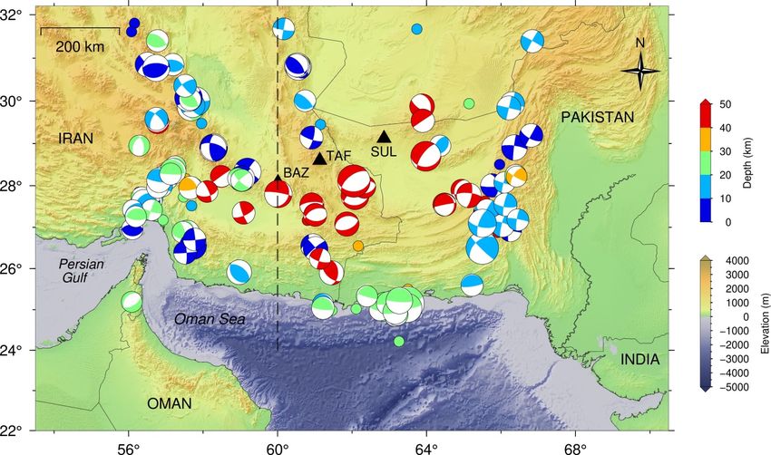
520

521
522 Fig. 5 Considered fault locations in this study which completely cover the MSZ

523
524 3_ Probabilistic tsunami hazard analysis (PTHA)
525 Due to the uncertainties of the seismic magnitude, fault location, slip distribution, seismicity depth, and splay
526 fault we have considered a number of scenarios according to Table 2 and have performed numerical simulation
527 for each one (section 3-1).
528 Based on the results of these simulations, for each magnitude and each wave height 0 , the probability of
529 the wave height exceeding a given value of 0 , ( > 0 | ) can be obtained. This probability is obtained by
530 integration over the aleatory uncertainties representing the natural uncertainty in the expected wave amplitudes
531 given a specific magnitude of tsunamigenic earthquake.
532 Hazard curves are obtained for different branches of logic-tree representing epistemic uncertainty.
533 For each branch of the logic tree, the annual exceedance rate ν( 0 ) is calculated based on the following
534 equation:
535

 (5)
 ( 0 ) = � ( ) ( > 0 | )
 =
536
537 Where ( ) is the annual frequency of earthquakes with magnitudes ± ∆ /2. The magnitude bin size ∆
538 is set as 0.2 magnitude units (see Table 3).
539 In the logic tree branches where the activities of the eastern and western zones of Makran are considered
540 different, the random slip distributions, related seabed deformations, and resulting tsunamis for each zone are
541 simulated separately during calculation of the exceedance rate. For these branches, the exceedance rate ν( 0 ) is
542 calculated based on the following:
543

 ( 0 ) = � � ( ) ( > 0 | ) (6)
 =1 =
544
545 Where Segments is equal to 2 (eastern and western MSZs) and ( ) is the annual frequency of earthquakes on
546 source with magnitudes between ± ∆ /2.
547 The calculation of P (Z> 0 | m) can be done in two ways. The first method is to form a set of simulated wave
548 heights at the desired point, which are obtained by considering all scenarios with in the magnitude bin ± ∆ /2.
549 Then a wave height like 0 is selected and the number of wave heights that are greater than 0 is counted in the

 17
550 set. The ratio of the number of scenarios with wave heights greater than 0 to the total number of the scenarios
551 provides the intended probability at the desired point, which is called here as the real probability.
552 In the second method, it is assumed that the desired probability follows the log-normal distribution (e.g.
553 Kulkarni et al., 2016). Therefore, by calculating the mean and standard deviation of the set of simulated wave-
554 heights, the log-normal distribution is fitted to them.
555 Fig. 7 shows the comparison of the real probability distribution and log-normal distribution in calculating P
556 (Z> 0 │m), which is presented according to the simulation results for a point on the coast of Chabahar and shows
557 that two approaches give similar results, at least for probabilities higher than 0.05.
558 Then based on the assumptions of the logic tree, we calculated the probabilistic tsunami hazard curves for all
559 of its branches and formed the statistical population for different hypotheses of the exceedance rate. Based on the
560 formed sample population, for each wave height, we calculated exceedance rate at the average, 16%, 50% and
561 84% percentiles of distribution.
562 Fig. 8 shows an example of these calculations for a point located on the coast of Chabahar. By reading the
563 wave height in the values of 1/475 and 1/2475 from the output hazard curve, it is possible to calculate the value
564 of the wave height in the 475-year and 2475-year return periods, at different levels of confidence. It is worth
565 noting that a group of hazard curves relating to the eastern Makran scenarios are located below others in Fig. 8.
566 The reason for the lower hazard is that Chabahar is in the western Makran, whereas all of the source zones in
567 those scenarios are located in the eastern Makran, therefore, the source-receiver distance is comparatively longer
568 for this group.
569
570

 a. Mw 8

 b. Mw 8.4

 c. Mw 9.0
571 Fig. 6 Six examples of generated slip distribution scenarios in this study a. Mw 8.0, b. Mw 8.4, and c Mw 9.0

 18
572 Table 2. Number of numerically simulated scenarios due to different fault locations, rupture depth/geometry, and fault slip
573 distribution uncertainties. It is notable that item "number of fault depth / geometry scenarios" includes splay faults too.

 Number of fault Number of fault depth / Number of
 Seismic magnitude
 locations geometry scenarios slip distribution scenarios Total
 7.7-7.9 10 4 12 480
 7.9-8.1 7 4 12 336
 8.1-8.3 6 4 12 288
 8.3-8.5 5 4 12 240
 8.5-8.7 4 4 12 196
 8.7-8.9 3 4 12 144
 8.9-9.1 2 4 12 96
 9.1-9.3 2 4 12 96
 Total 1872
574

575 3-1- Tsunami numerical modelling
576 The tsunami phenomenon consists of three main phases: generation, propagation, and inundation. Underwater
577 earthquakes are the main cause of about 80% of tsunamis (Løvholt 2017). Therefore, we consider only these kind
578 of earthquakes as tsunami sources.
579 If the total rupture time of an earthquake is much shorter than the period of the tsunami wave, the seabed
580 displacement is considered as an instantaneous motion. This method is conventionally called passive seismic
581 generation (Dutykh et al. 2006; Kervella et al. 2007). By using this method, static (rather than dynamic)
582 displacement is considered for the seabed due to earthquake. It is also assumed that the initial amplitude of the
583 tsunami wave is exactly the same as the amount of vertical displacement of the seabed, because the water of this
584 vast area affected by fault sliding cannot be drained within the rupture time (Steketee 1958). Therefore, the initial
585 conditions for the propagation of tsunami waves are obtained by transferring the final vertical static displacement
586 of the seabed to the water surface. Okada's (1992) closed form solution is used to obtain vertical displacement in
587 the seabed. According to this solution, in a semi-infinite homogeneous environment, if the fault is rectangular and
588 the amount and direction of slip are constant everywhere on the fault, a closed form solution can be written to
589 obtain displacement anywhere in the space. For the faults with non-constant slip, the fault is divided into a number
590 of sub-faults, that can be treated separately and the final displacement of the seabed is equal to the sum of all sub-
591 fault displacements based on the superposition principle.
592 The source rupture modeling parameters used in this study are listed in Table 3. After tsunami waves are
593 generated, they propagate through the water. The most common equations to describe the propagation of tsunami
594 waves are the shallow water equations, which are derived from mass and momentum continuity. These equations
595 assume that the horizontal scale (wavelength) is much larger than the vertical scale (water depth). The second
596 assumption for these equations is that the viscous effect is ignored. As a result of these two assumptions, the
597 horizontal velocity of the waves will be much higher than the vertical velocity of the waves, the horizontal velocity
598 of the wave will be constant at depth and the pressure will be hydrostatic.
599 This study adopts COMCOT (COrnell Multi-grid COupled Tsunami Model; Liu et al., 1998) as the kernel to
600 perform tsunami modeling. COMCOT supports both linear/nonlinear shallow water equations for tsunami
601 simulations with the two-grid nesting scheme for flexible computational grid sizes and time steps crossing
602 multiple layers and moving boundary scheme for calculating coastal inundation areas and flood depths. On the
603 one hand, in deep-water regions where the nonlinear effect is ignored, the linear shallow water equations are used
604 for simulating a proposed tsunami from its original source to nearshore regions. On the other hand, in shallow-
605 water regions where tsunami waves are amplified by the shoaling effect and bathymetry effect (see, e.g., Imamura
606 et al., 1998; Kajiura & Suto, 1990), the nonlinear equations are adopted for calculating nearshore tsunamis. It is
607 noted here that both linear and nonlinear shallow water equations are conducted in the spherical coordinate.
608 As the wavelength of tsunami waves changes due to the water depth, the grid sizes and time steps shall be
609 modified accordingly. Thus, we consider the three-layer nested-grid configuration to simulate tsunami waves
610 propagating from offshore to nearshore (see Fig. 9).

 19
You can also read