Spider-Inspired Electrohydraulic Actuators for Fast, Soft-Actuated Joints
←
→
Page content transcription
If your browser does not render page correctly, please read the page content below
RESEARCH ARTICLE
 www.advancedscience.com

Spider-Inspired Electrohydraulic Actuators for Fast,
Soft-Actuated Joints
Nicholas Kellaris, Philipp Rothemund, Yi Zeng, Shane K. Mitchell, Garrett M. Smith,
Kaushik Jayaram, and Christoph Keplinger*

 1. Introduction
The impressive locomotion and manipulation capabilities of spiders have led
to a host of bioinspired robotic designs aiming to reproduce their The field of soft robotics endeavors to repro-
 duce the versatility of natural organisms—
functionalities; however, current actuation mechanisms are deficient in either
 in particular their ability to interact effec-
speed, force output, displacement, or efficiency. Here—using inspiration from tively with uncertain and dynamic external
the hydraulic mechanism used in spider legs—soft-actuated joints are forces or environments—through the in-
developed that use electrostatic forces to locally pressurize a hydraulic fluid, corporation of elasticity and compliance
and cause flexion of a segmented structure. The result is a lightweight, into robotic structures.[1–12] Naturally, soft-
low-profile articulating mechanism capable of fast operation, high forces, and bodied animals[13] that undergo continuum
 deformation, such as annelids,[14] insect
large displacement; these devices are termed spider-inspired electrohydraulic
 larvae,[15] and molluscs,[16] are often used
soft-actuated (SES) joints. SES joints with rotation angles up to 70°, blocked as model organisms in soft robotics.[17–19]
torques up to 70 mN m, and specific torques up to 21 N m kg−1 are However, the functional capabilities of
demonstrated. SES joints demonstrate high speed operation, with measured these soft robots, such as weight sup-
roll-off frequencies up to 24 Hz and specific power as high as 230 W port against gravity,[20] body/appendage
 control,[21] and rapid propulsion,[22] could
kg−1 —similar to human muscle. The versatility of these devices is illustrated
 be further enhanced by incorporating
by combining SES joints to create a bidirectional joint, an artificial limb with arthropod-inspired articulated exoskeletal
independently addressable joints, and a compliant gripper. The lightweight, mechanisms[23] comprised of both rigid
low-profile design, and high performance of these devices, makes them and compliant elements, all while main-
well-suited toward the development of articulating robotic systems that can taining impressive compliance, e.g., for
rapidly maneuver. navigating confined spaces.[23]
 Amongst the arthropods, spiders (class
 Arachnida) feature one of the most suc-
 cessful and unique solutions for achieving
 motion in nature, as they integrate compliant articulation with
 fluidic actuation.[24] Unlike most animals that use antagonistic
 muscle pairs for generating movement, spiders create leg exten-
Dr. N. Kellaris, Dr. P. Rothemund, Y. Zeng, Dr. S. K. Mitchell, G. M. Smith,
Prof. K. Jayaram, Prof. C. Keplinger sion through the use of hydraulic mechanisms, while using elas-
Paul M. Rady Department of Mechanical Engineering tic elements or muscles for flexion.[25] This hydraulic mechanism
University of Colorado supplies the precise and coordinated motion needed to weave
Boulder, CO 80309, USA complex webs,[26] as well as the powerful and fast maneuvers
E-mail: ck@is.mpg.de
 needed to hunt prey,[27,28] making spiders a prime source of bioin-
Dr. N. Kellaris, Prof. C. Keplinger
Materials Science and Engineering Program spiration for mechanisms of soft actuation.
University of Colorado Developing capable articulating robots that can reproduce
Boulder, CO 80303, USA animal-like functionality necessitates the use of a lightweight ac-
Dr. P. Rothemund, Prof. C. Keplinger tuation mechanism capable of high speed and high force output,
Robotic Materials Department large displacements, and compatibility with untethered opera-
Max Planck Institute for Intelligent Systems
 tion. While myriad actuation strategies exist, no single technol-
Stuttgart 70569, Germany
 ogy yet satisfies all these requirements. Pneumatics—the most
 popular approach[29–32] —requires bulky peripheral components
 The ORCID identification number(s) for the author(s) of this article such as tubes and valves and is plagued by tradeoffs between
 can be found under https://doi.org/10.1002/advs.202100916
 portability and speed: fast operation requires tethers to large
© 2021 The Authors. Advanced Science published by Wiley-VCH GmbH.
This is an open access article under the terms of the Creative Commons
 reservoirs of pressurized fluid or pumps, while the speed of un-
Attribution License, which permits use, distribution and reproduction in tethered systems is low.[3,17] Thermally driven systems achieve
any medium, provided the original work is properly cited. high specific energies, but demonstrate low bandwidth and
DOI: 10.1002/advs.202100916 efficiencies.[33,34] Piezoelectric mechanisms on the other hand

Adv. Sci. 2021, 2100916 2100916 (1 of 16) © 2021 The Authors. Advanced Science published by Wiley-VCH GmbH
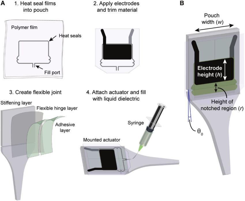
www.advancedsciencenews.com www.advancedscience.com

exhibit high speed and portability,[35,36] but have limited displace- 2. Results
ment. Finally, dielectric elastomer actuators (DEAs) offer high ef-
ficiencies and speed,[37,38] even in untethered operation,[39,40] but 2.1. Principles and Capabilities of SES Joints
require highly elastic dielectrics and stretchable electrodes[41] —
both challenging material systems to work with—and the demon- 2.1.1. Principles of Operation for Spider Joints
strated torque production in articulated designs based on DEAs
is low.[42,43] The basic structure of a spider leg joint[25,52] creates extension
 Electrohydraulic actuation mechanisms, as used in hydrauli- through hydraulic pressure (Figure 1A). A stiff exoskeleton is
cally amplified self-healing electrostatic (HASEL) actuators, segmented by a compliant joint with a soft bellowed membrane
address some of these technological gaps by demonstrating on the ventral side of the joint. The lacuna—the empty space in
many of the advantages of both fluidic and electrostatic actu- the exoskeleton—contains the spider’s hemolymph, which acts
ators, with muscle-like forces, high bandwidth, and promising as both its “blood” and a hydraulic fluid.[53] Hemolymph is pres-
efficiencies.[44–47] Peano-HASEL actuators in particular exhibit surized by muscles in the prosoma of the spider, and the soft bel-
attractive characteristics for bioinspired robotic systems due to lowed membranes in the joint expand on pressurization, caus-
their controllable linear contraction, scalable fabrication, and ver- ing the leg to extend.[29,50] Restoring forces to provide flexion
satility in materials; however, the integration of Peano-HASEL rely on either passive elastic components or muscles within the
actuators into distributed articulating systems is difficult due to exoskeleton.[54]
the need to convert linear movement into angular output; this
requirement increases design complexity, introduces additional 2.1.2. Principles of Operation for SES Joints Analogous to Spiders
components, and limits the angular excursion of articulating
structures. Our SES joints aim to combine many of the central character-
 Several pneumatic technologies have emphasized the ad- istics of the anatomy of spider joints to recreate their function-
vantages of mechanical anisotropy in articulating structures, alities (Figure 1B). They use an electrohydraulic driving compo-
including the integration of rigid structural components with nent that consists of 1) a flexible pouch made from dielectric film
soft actuation for articulation from mm to cm scales.[30,31,48–50] In filled with 2) a liquid dielectric, and 3) a pair of flexible electrodes
particular, the pouch motors introduced by Niiyama et al. provide placed on opposing sides of the pouch (Figure 1B). This electro-
a promising approach for articulation through their distributed hydraulic component is integrated with a passive stiffening layer
design and control, but still suffer from the common pitfalls of that acts as the exoskeleton to provide support and selective de-
pneumatics with the need for a supply of compressed air that formation by constraining one side of the liquid-filled structure;
is distributed through complex networks of lossy air lines; thus, an elastic hinge is located along the stiffening layer, which allows
these are still limited in their bandwidth and controllability for flexion of the joint, and provides an elastic restoring force, simi-
multiple degrees of freedom. lar to that used in many spiders.[25,54] On application of DC high
 Here, to address the need for high-performance actuators voltage (on the order of kilovolts), Maxwell stress causes the elec-
that enable fast articulation and can be seamlessly integrated trodes to zip together progressively, pressurizing and pumping
into robotic structures, we introduce an actuation approach that the fluid;[45–47,55] the hydrostatic pressure coupled with the selec-
enables a family of devices termed spider-inspired electrohy- tive constraints causes flexion of the joint (Figure 1B,C; Movie
draulic soft-actuated (SES) joints. SES joints leverage qualities S1, Supporting Information). The unique combination of electro-
of both linear Peano-HASEL actuators[45] and rotational pouch static and hydraulic forces coupled with discrete stiffening layers
motors[31,51] and feature high specific torque (comparable to elec- results in a soft-actuating joint with capabilities that are attractive
tromagnetic servo motors), fast operation (demonstrated up to for robotics applications such as efficient force transmission (Fig-
24 Hz), low power consumption, and backdrivability, all in a low ure 1D), backdrivability (Movie S2, Supporting Information), the
profile and lightweight design that exploits versatile fabrication ability to be parallelized (Figure 1E; Movie S3, Supporting Infor-
methods. These SES joints leverage both rigid and compliant mation), and fast and strong actuation that enables the creation
structural elements to produce a bioinspired high-performance of robots that can leap into the air over ten times their body height
articulating mechanism that is driven by electrohydraulic princi- (Figure 1F; Movie S4, Supporting Information).
ples. A quasi-static model of SES joint performance is developed
and experimentally validated in order to provide a tool for inform-
ing design improvements. To illustrate potential applications of 2.1.3. Fabrication Procedure for SES Joints
these joints in robotics systems, we implement a range of struc-
tures with different functionalities such as a jumping robot that The fabrication process for SES joints is simple and customiz-
can leap over 10 times its height, a fast-acting bidirectional joint able, which allows them to be tailored for desired properties
that operates over 10 Hz, a multisegmented artificial limb with by modifying films, liquid dielectrics, electrodes, hinges, and
three independently addressable joints, and a three-finger grip- stiffening layers as described below. The basic procedure relies
per capable of both delicate and powerful grasps. The structural on the integration of a variable-stiffness structure with a high-
simplicity of SES joints allows direct integration of actuation at performance electrohydraulic component, for which the fabrica-
the joint, with minimal peripheral components, thereby opening tion procedure is based on techniques introduced by Mitchell
new opportunities for the creation of more complex, bioinspired et al. for HASEL actuators.[46] Details are provided in the Sup-
structures with multiple degrees-of-freedom. porting Information, while an overview is provided in Figure 2A.

Adv. Sci. 2021, 2100916 2100916 (2 of 16) © 2021 The Authors. Advanced Science published by Wiley-VCH GmbH

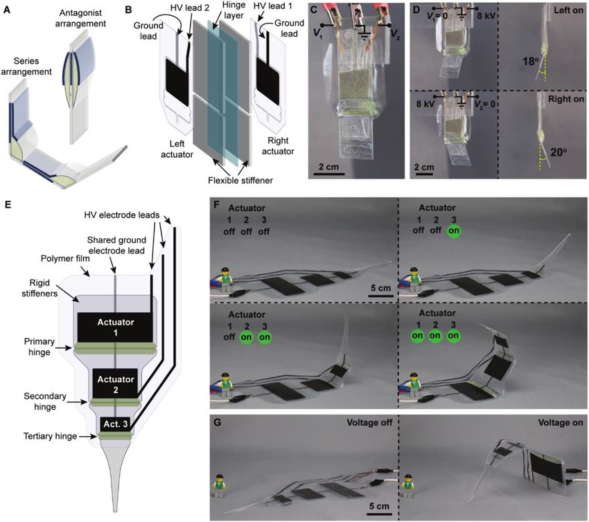
www.advancedsciencenews.com www.advancedscience.com

Figure 1. Principles of spider-inspired electrohydraulic soft-actuated (SES) joints. A) Hydraulic operation of the tibia-metatarsus joint of a spider. Pres-
surization of hemolymph fluid causes the leg to extend. Adapted with permission.[51] Copyright 2014, IEEE. A wolf spider (family Lycosidae) is pictured.
B) SES joints consist of a flexible pouch filled with liquid dielectric, and a pair of opposing electrodes on the outside. A stiffening layer is placed on one
side to constrain actuation while a flexible hinge provides stability and a passive restoring force. On application of voltage, Maxwell stress causes the
electrodes to zip together progressively, which pressurizes the liquid dielectric (P) and causes flexion of the joint to angle . C) SES joint with voltage off
and with voltage on (8 kV applied), which causes flexion of the joint. D) The rigid stiffening layer supports efficient force transfer along the limb; here,
a 1.3 g actuator is lifting 20 g almost 10 cm away from the point of rotation. E) Multiple SES joints can be combined to create different types of robotic
structures. F) SES joints feature excellent power-to-weight ratio and can be used to create jumping robots.

 Step 1: Two dielectric films are heat-sealed together to form a to the stiffening layer. The default stiffening layer was acrylic that
pouch using a CNC-controlled heat sealer. A fill port is left open was laser cut into shape.
for later filling with liquid dielectric. Step 2: Flexible carbon-based A schematic of a completed joint is shown in Figure 2B. Ac-
electrodes are printed on both sides of the film using a screen- tuator dimensions are characterized by h × w × r, where h is the
printing method. Excess film is trimmed to reduce constraints height of the electrodes in cm, w is the width of the pouch (and
on actuation, leaving a skirt to prevent electrical arcing around electrodes) in cm, and r is the height of the notched region of the
the actuator during application of high voltage. Step 3: A flexible pouch, uncovered by electrodes, in cm. Completed joints have a
joint is created by bonding a flexible hinge layer to a two-piece natural resting angle, 0 , of 10°–15° (under no load) that results
stiffening layer. This stiffening layer can be flexible or rigid. The from the deformation caused by mounting the actuators empty
hinge stabilizes the joint against lateral loading and provides an then filling with liquid dielectric (Figure 2B).
elastic restoring force. An adhesive layer (e.g., transfer tape) is
applied to the joint for mounting the actuator. Step 4: The empty
actuator is adhered to the joint, then filled with liquid dielectric 2.2. Quasi-Static Actuation Performance
through the fill port. A syringe with a bent needle allows access
to the fill port while the actuator is mounted. Finally, the fill port 2.2.1. High Torque Production
is sealed using a heated soldering iron tip.
 For SES joints tested in this work, the default hinge layer was a The torque output of SES joints was measured as a function of
75 µm thick transparency with adhesive on one side, for bonding hinge angle, . Actuators with various dimensions, h × w × r

Adv. Sci. 2021, 2100916 2100916 (3 of 16) © 2021 The Authors. Advanced Science published by Wiley-VCH GmbH
www.advancedsciencenews.com www.advancedscience.com

Figure 2. Fabrication process for SES joints. A) Representative fabrication steps for the material systems used in this paper. 1) Two layers of polymer
film are heat sealed together to define a pouch shape, leaving a small opening at the bottom for filling. 2) Carbon electrodes are screen printed on
either side of the pouch; excess film is trimmed from the sides, leaving a skirt on the sides and bottom to prevent electrical arcing around the actuator
during operation. 3) The flexible joint is made from a flexible hinge layer bonded to a two-piece stiffening layer with much higher mechanical stiffness.
An adhesive layer is applied over the transparency to connect the actuator to the joint. 4) The pouch is bonded to the flexible joint and filled with liquid
dielectric using a syringe with an angled needle inserted into the filling port. The filling port is then closed by heat sealing. B) The completed SES joint
is characterized by the electrode height (h), the pouch width (w), and the height of the notched region that is not covered by electrodes (r). Joints have
a natural resting angle, 0 .

(Figure 2B), were measured using two types of film: 18 µm the actuator, r, which changes the amount of liquid dielectric and
thick biaxially oriented polypropylene (BOPP) and 20 µm thick therefore the hydraulic coupling. For the same geometry, using
polyester film, brand name L0WS. L0WS was tested as a higher L0WS film resulted in torques ≈50% higher than BOPP at the
permittivity film (measured r = 3.15, see Supporting informa- same voltage, due to L0WS’ higher permittivity, which increases
tion) that should have better overall performance compared to the Maxwell stress in the actuator.[57] Changing actuator dimen-
BOPP ( r = 2.2[56] ). The liquid dielectric used was an ester-based sions from 2 × 4 × 1 to 4 × 4 × 1 cm had no demonstrable effect
transformer oil called Envirotemp FR3, with fill amounts for each on torque output, as the actuators were filled with nominally the
pouch given in Table S1 of the Supporting Information. A custom same fluid volume, so the hydraulic coupling was unaffected.
setup was used to measure torque (Figure S1, Supporting Infor- Specific torque (N m kg−1 ) is an important metric for rotational
mation). Details of this setup and the measurement procedure actuators used in robotic design.[58,59] For SES joints, the specific
are provided in the Supporting Information. The testing voltage torque is independent of the width of the actuator (i.e., the out-
was a modified square wave with amplitude 9 kV (Figure S1E, put torque of an SES joint can readily be scaled up by increas-
Supporting Information). ing its width). A maximum specific torque of 21.2 N m kg−1 was
 Measured torque versus angle curves are shown in Figure 3A achieved for the 2 × 4 × 1 L0WS joint, only considering the mass
for several actuator geometries using BOPP and L0WS films. The of the actuator (1.36 g), or 2.3 N m kg−1 if including mass of the
measured torque was relatively constant at low angles (at or be- entire joint tested (12.6 g); normalizing to the mass of the ac-
low the natural resting angle), and at higher angles, it decreased tuation component alone is the most accurate representation of
in a roughly linear trend. Torques up to 70 mN m and free angles the specific torque of SES joints as SES joints can easily leverage
up to 70° were measured. Comparing the measured torque–angle the mechanical components inherent to the robotic structure as
curves of the different actuator geometries revealed a linear scal- the stiffening layer for articulation. This direct integration at the
ing of the output torque with actuator width, w. The generated joint avoids the need for additional mass and complexity in the
torque also increased with the height of the notched region of system. Specific energy (J kg−1 )—a closely related metric—was

Adv. Sci. 2021, 2100916 2100916 (4 of 16) © 2021 The Authors. Advanced Science published by Wiley-VCH GmbH

www.advancedsciencenews.com www.advancedscience.com

Figure 3. Evaluation of quasi-static actuation performance in SES joints. A) Torque versus angle curves at 9 kV for SES joints with varying pouch geometry
(h × w × r) and film material. For the same voltage, using L0WS increased torque output by ≈ 50% (compared to BOPP). B) Angle versus voltage curves
for joints with varying hinge thickness (corresponding to hinge stiffness). Less stiff hinges reached higher angles at a given voltage. C) Angle versus
voltage curves for joints made from BOPP films with zero- and 10 g external loads (3.5 cm away from the hinge). Hinges were tested horizontally, with
the direction of the gravitational force denoted by Fg .

calculated by integrating under the torque versus angle curve for act to increase the lateral stiffness of the joints, prevent buckling
an SES joint. The 2 × 4 × 1 L0WS joint demonstrated the highest under large moments, and provide a stronger elastic restoring
specific energy, 10.3 J kg−1 , again only considering the mass of force; therefore, a 75 µm hinge was chosen for general use. Fig-
the actuator. ure 3C shows the controllable angular output of SES joints as
 a function of activation voltage using a 2 × 4 × 1 BOPP actua-
 tor with FR3 under both 0 and 10 g external loads. In addition to
2.2.2. Continuous and Tunable Angular Output controllable angular output, SES joints exhibited repeatable actu-
 ation for over 2000 cycles with less than a 3% change in angular
SES joints have a controllable angular output that is determined output between the first 25 and last 25 cycles (Figure S3, Support-
by the voltage applied to the electrodes. To characterize angle ver- ing Information). The SES joint demonstrated 2800 cycles until
sus voltage curves, the joints were mounted horizontally on an failure, which occurred via dielectric breakdown through the heat
acrylic stand; a laser displacement sensor was mounted to the seal. This failure was caused by gradual damage from repeated
stand a defined distance from the joint (Figure S2A,B, Supporting electrical discharges through the air, emanating from the leads
Information) and a transform was applied based on the known of the electrodes. Suppressing these discharges through meth-
geometry of the stand to convert measured distance to joint rota- ods such as encapsulation of the electrodes in a dielectric mate-
tion angle (Equation (S1), Supporting Information). The joints rial would likely improve lifetime substantially.
were tested using the same signal used for testing torque (Figure
S1E, Supporting Information).
 Figure 3B shows the output hinge angle as a function of volt- 2.3. Modeling Quasi-Static Response
age for 2 × 4 × 1 cm BOPP actuators with FR3 fluid using var-
ious thickness (i.e., stiffness) hinges and no external load. An- In this section we derive a 2D model for the quasi-static response
gle versus voltage curves displayed an activation voltage below of SES joints in order to provide a basis for informing future de-
which no deformation occurred (as observed previously in Peano- signs and geometries.
HASEL actuators[57] ). After deformation began, the output angle
increased monotonically with a slower-than-linear rise. As seen
in the plot, hinge thickness influenced the angle versus voltage 2.3.1. Parameterization of Actuator Geometry
curve when no external loads were present, with the maximum
angle of thin (i.e., soft) hinges being larger. With no elastic hinge, In this model we distinguish three states (Figure 4A–C). In the
rotation angles of nearly 80° were observed (the actuator pouch undeformed state (Figure 4A), the hinge is flat. It consists of
was adhered directly to the acrylic supports without a separate a fixed rigid support (length L1 ), and a rotating rigid support
hinge layer). The angle versus voltage curves for hinges of var- (length L3 )—together these make up the stiffening layer for the
ious thickness should converge as loads are increased and the joint. An empty shell (length L, width w) is bonded to the flat
stiffness of the hinge becomes negligible; further, thicker hinges hinge, so that a portion of length L1 attaches to the fixed support

Adv. Sci. 2021, 2100916 2100916 (5 of 16) © 2021 The Authors. Advanced Science published by Wiley-VCH GmbH
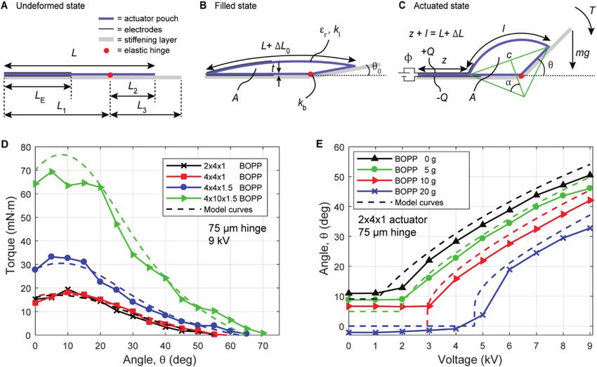
www.advancedsciencenews.com www.advancedscience.com

Figure 4. Quasi-static model of the SES joint. A) Undeformed state: an empty shell (length L, width w out of the plane of the figure) that is covered
on both sides with electrodes (length LE , width w out of the plane of the figure) is bonded to a stiffening layer (assumed to be rigid); a portion (length
L1 ) attaches to the stationary side, and the remaining portion (length L2 ) attaches to the rotating side (length L3 ). B) Filled state: when filled with an
incompressible liquid dielectric, the cross-sectional area of the shell (thickness t, relative permittivity r ) increases to A and the hinge (spring constant
kb ) rotates by an angle 0 . Elastic strains in the shell and the joint between shell and stiffening layer (assumed to be rigid) are modeled as an elongation
ΔL0 of the top film of the shell (spring constant kl ). C) When a voltage Φ is applied between the electrodes, they zip together by a length z and the hinge
rotates to an angle . The top film elongates by ΔL. The unzipped portion of the top film is modeled as a cylinder section of length l with central angle
2 and chord length c. Note that A remains constant. We modeled two cases: either a torque T or a vertical load mg acts on the end of the hinge. D,E)
Comparison of model predictions with experimental results.

and the remaining portion ( L2 = L − L1 ) to the rotating sup- where 2 is the central angle of the top film and
port. The shell is covered on both sides with electrodes of length √
LE (= h in Figure 2B). In the filled state (Figure 4B), the shell is ( )2
 c= L1 − z + L2 cos ( ) + L22 sin( )2 (2)
filled with an incompressible liquid dielectric (volume V), which
causes the hinge to rotate by an angle 0 . The cross-sectional area is the chord length of the top film. In this state, the cross-sectional
of the filled shell is A = V/w. We treat the top film of the shell area of the liquid-filled region of the shell can be calculated with
as a membrane with negligible bending stiffness, so it takes the
shape of a cylinder section.[31] To account for the elasticity of the l2
 A= (2 − sin (2 ))
shell and the imperfect connection (subject to delamination) be- 8 2
tween the shell and the rigid supports we model the top film as √
 ( ( )2 )2 ( ( )4 )
extensible (extension ΔL0 , spring constant kl ). The stiffness of 1
 + c2 + L1 − z + L22 − 2 c4 + L1 − z + L42 (3)
the transparency that forms the hinge is modeled as a torsional 4
spring with spring constant kb . In the zipped state (Figure 4C), a
sufficiently large voltage Φ is applied to the electrodes such that where l = L + ΔL − z is the length of the cylindrical section of
they zip together from the edge of the shell over a length z, dis- the top film (Figure 4C). Because the liquid dielectric is treated as
placing the liquid dielectric and causing the hinge to rotate to an incompressible, the value of A does not change during actuation.
angle . The elongation of the top film changes to ΔL and can be
calculated with 2.3.2. Energy Minimization

 c To determine the equilibrium position of the electrohydraulic
ΔL = +z−L (1) hinge we calculate the extrema of the Helmholtz free energy
 sin ( )

Adv. Sci. 2021, 2100916 2100916 (6 of 16) © 2021 The Authors. Advanced Science published by Wiley-VCH GmbH
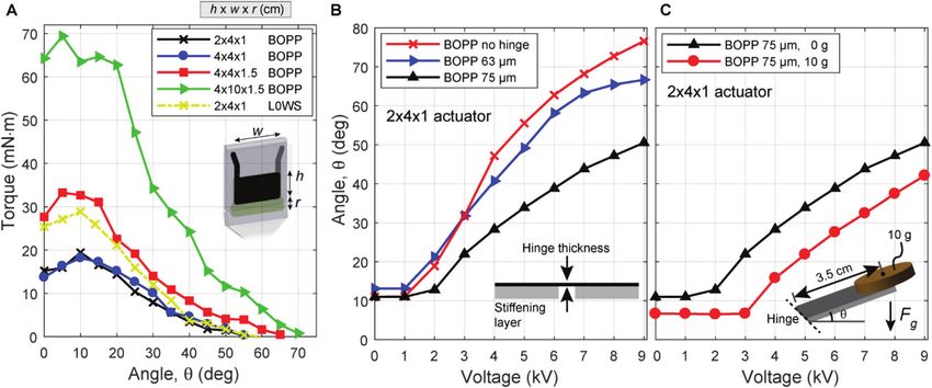
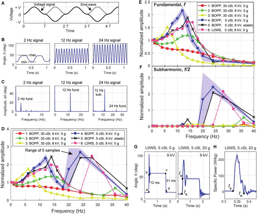
www.advancedsciencenews.com www.advancedscience.com

F of the system (the electrohydraulic joint, the voltage source, Since the experiment was carried out “angle-controlled,” the mea-
and an external load). The elastic energy stored in the torsional sured torque–angle curve followed the model predictions (in a
spring and the shell are (kb 2 )/2 and (kl ΔL2 )/2 respectively. When “torque-controlled” experiment this region of the torque–angle
charges Q flow onto the electrodes, the energy of the voltage curve would not be stable). The reason for this snap-through in-
source reduces by − QΦ. Electrically, the actuator can be treated stability is the elasticity described by kl .
as a deformable capacitor (capacitance C); when charges Q flow The model also predicted angle–voltage curves of joints for
onto the actuator, the stored electrical energy is Q2 /2C. In this constant vertical loads very well (load case (ii), Figure 4E). In
model, we neglect the electric field in the liquid-filled region of these calculations, we used the same values for kb and kl as above
the pouch[57,60] and model the zipped region of the electrodes as a and included the torque due to the weight of the rotating support
parallel plate capacitor with capacitance C = ( 0 r wz)/2t, where (2.5 g at L3 /2) by adding an equivalent mass of 1.25 g to the ex-
 0 is the vacuum permittivity, r is the relative permittivity of the ternal mass, which was located at L3 from the hinge. The model
film, w is the width of the actuator, z is the length of the zipped accurately predicted the presence of an activation voltage, below
region of electrodes, and t is the thickness of the film that forms which no deformation occurred.
the actuator shell (Figure 4). We model two load cases: i) A con-
stant torque T is applied to the rotating support. Referenced to
the undeformed state, the free energy of the load is Fe = T . ii) 2.4. Dynamic Actuation Performance
A mass is attached to the end of the rotating support. Referenced
to the undeformed state, the potential energy of the load is Fe = SES joints inherit the fast dynamics of HASEL actuators, which
 mgL3 sin ( ). The total free energy of the system, thus, becomes are based on the speed of electrostatics and the local displacement
 of fluids.[62] The nonlinearity of these systems and their tunable
 ( ) 1 1 1 2t
F Q, z, , = kb 2 + kl ΔL( , z)2 − Q + Q 2 response will be consequential for considerations of designs in
 2 2 2 0 r wz robotic structures. Therefore, here we explore some of the fac-
 + Fe ( ) (4) tors affecting the bandwidth and dynamic characteristics of SES
 joints.
 We numerically determine the extrema of Equation (4) using
the constraint of Equation (3), 0 < z < LE (z is limited to be within
the electrodes), and > 0 (contact between the rigid supports 2.4.1. High Bandwidth Actuation Response
prevents bending the hinge to negative angles).
 The bandwidth was tested for SES joints in several different con-
 figurations from 0.25 to 40 Hz, using the same experimental
2.3.3. Model Validation setup as angle–voltage measurements (Figure S2, Supporting In-
 formation). To identify the effect of material and testing param-
We validated the model for joints made with BOPP film (t = eters on bandwidth, actuators with dimensions 2 × 4 × 1 cm
18 µm, r = 2.2). For pouch width w = 4 cm, we estimated kb = were fabricated using two types of film (18 µm BOPP and 20 µm
4.2 mN m rad−1 , using material properties of E ≈ 2 GPa and ≈ L0WS) and liquid dielectrics with two viscosities (FR3 liquid di-
0.4 for the PET film used in the hinge (Figure S4A,B, Support- electric, > 30 cSt;[63] silicone oil, = 5 cSt[64] ). One joint was
ing information).[61] It is difficult to calculate a value for kl so we tested with an external load of 5 g (3.5 cm from the hinge) while
used it as a fitting factor. Using a value of kl = 17.5 N mm−1 (de- the remaining joints had no external load. All joints were tested
termined by visually fitting curves) the calculated torque–angle with a modified sine wave (Figure 5A)—one joint was tested at
curves for the BOPP joints agreed very well with the measured 6 kV, with the remaining tested at 8 kV.
torque–angle curves over the entire range of angles (Figure 4D). Figure 5B shows the 8 kV angle versus time response of a
The model behavior and fit to data is relatively insensitive to small BOPP joint with 5 cSt fluid for driving signal frequencies of 2,
changes in kl , while model behavior without this fitting factor 12, and 24 Hz. From the plots, we see that the joint responds at
is unrealistic, predicting asymptotic torque growth at low angles the same frequency for both the 12 and 24 Hz driving signals. A
(Figure S5, Supporting Information). For the joint made from 10 discrete Fourier transform (DFT) of these responses (Figure 5C)
cm-wide BOPP, we estimated kb = 9.2 mN m rad−1 (see Support- helps explain this unusual behavior—while the joint responds to
ing Information for details) and increased kl by a factor of 2.5 to 2 and 12 Hz signals at the fundamental frequency, the response
43.75 N mm−1 to account for the larger width. Using this fitting to the 24 Hz signal occurs primarily at 12 Hz, corresponding to
factor, we observed very good agreement between model and ex- a subharmonic resonance of the system (specifically the second
periment for the wider actuator (Figure 4D). subharmonic, fresponse = fsignal /2).
 The model explains the shape of the torque–angle curves (load The frequency response for several SES joints and test con-
case (i), explained above). When no torque is applied to the joint, ditions is plotted in Figure 5D, with the x-axis plotting the fre-
the deformation of the joint is only resisted by the bending stiff- quency of the driving signal, and the y-axis plotting the differ-
ness of the hinge and the joint achieves the largest angles (if the ence between the periodically-occurring minima and maxima of
hinge had no bending stiffness larger angles would be possible the angle (Figure 5B). These amplitudes are normalized to the
(Figure 3B)). With increasing torque, the equilibrium angle de- amplitude of the lowest measured frequency response (0.25 Hz).
creases until it reaches a maximum at the filling angle 0 . At 0 For all joints using the 5 cSt fluid, a strong resonance peak can be
a snap-through instability occurs (i.e., the downward portion of seen between 12 and 14 Hz (corresponding to the fundamental
the calculated curve for → 0 represents unstable equilibria). resonance as shown in Figure 5E) with a second larger resonance

Adv. Sci. 2021, 2100916 2100916 (7 of 16) © 2021 The Authors. Advanced Science published by Wiley-VCH GmbH
www.advancedsciencenews.com www.advancedscience.com

Figure 5. Evaluation of dynamic actuation performance in SES joints. A) The voltage signal used for testing frequency response was a modified sine
wave with amplitude V. B) Angle versus time responses of a 2 × 4 × 1 BOPP actuator with 5 cSt fluid at 8 kV. Note that the angular response to the 24 Hz
signal only had 12 maxima and minima in 1 s. C) The discrete Fourier transforms (DFTs) of the time domain responses in (B) showed a substantial
subharmonic resonance when driven by a 24 Hz signal (corresponding to 12 Hz response) due to the nonlinearity of SES joints. D) Frequency response
of actuators when analyzed using periodically occurring minimum and maximum values in the time domain (B) to determine amplitude, plotted against
the frequency of the driving voltage signal. Various combinations of pouch materials, liquid dielectrics, voltages, and loads were tested. Test 5 added
an additional elastic restoring force (Figure S7, Supporting Information). For test 4, the plotted line corresponds to the mean values from five tested
samples, while the shaded region is bounded by lowest and highest measured values for those samples. E) Amplitude of the fundamental response (C)
plotted against the frequency of the driving voltage signal. F) Amplitude of the subharmonic response (C) plotted against the frequency of the driving
voltage signal. G) Response of a 2 × 4 × 1 L0WS joint with 5 cSt fluid to a step voltage at 9 kV, with no load (left) and a 20 g load (right), and H) the
corresponding specific power output for a 20 g load.

peak occurring between 24 and 28 Hz (corresponding to a sub- observed (defined as amplitude = 50% of the 0.25 Hz response
harmonic resonance as shown in Figure 5F). amplitude). Several qualitative observations can be made from
 To analyze the behavior of the different joints in more detail we the data: the BOPP joint with FR3 exhibited flexion angles that
took a DFT of the time-domain response and recorded the ampli- decreased monotonically with frequency at 6 kV (test 1), while at
tude of the fundamental response. Figure 5E plots the amplitude 8 kV (test 2) a resonance was present (this behavior is explained in
of the response at the fundamental frequency as a function of Figure S6, Supporting Information). The resonant behavior was
the frequency of the driving signal (normalized to the response modified by adding an external load of 5 g on the joint (test 3) at
at 0.25 Hz). As shown in Figure 5E, the actuator bandwidth can be the expense of high-frequency actuation. Using a liquid dielec-
controlled by varying voltage, load, liquid dielectric viscosity, and tric with low viscosity (5 cSt silicone oil) led to strong resonance
elastic restoring force. Roll-off frequencies of up to 24 Hz were peaks in actuation and better low frequency response, but little

Adv. Sci. 2021, 2100916 2100916 (8 of 16) © 2021 The Authors. Advanced Science published by Wiley-VCH GmbH
www.advancedsciencenews.com www.advancedscience.com

change in roll-off frequency (test 4). Adding a prestrained elastic
band (Figure S7, Supporting Information) to the 5 cSt BOPP joint
increased the restoring force and improved the roll-off frequency
for the BOPP joint from 19 to 22 Hz (test 5). Finally, using L0WS
with low viscosity fluid (test 6) decreased the resonance peak,
likely due to the stiffer material, and resulted in a higher roll-off
frequency than the corresponding BOPP joint (test 4). Most tests
were performed with one joint; however, test 4 was performed
for five identical BOPP, 5 cSt joints to infer data spread for band-
width tests. The solid line for test 4 in Figure 5D–F represents
the mean values from these five samples, while the shaded re-
gion represents the range of the data.
 Figure 5F plots the second subharmonic amplitudes, nor-
malized to the 0.25 Hz fundamental frequency response. At
low frequencies subharmonic response was negligible, but at
frequencies above 10 Hz the subharmonic was activated; strong
subharmonic response has been observed previously in dielectric
elastomer minimum energy structures.[65] Figure 5D resembles
a superposition of the fundamental (Figure 5E) and second
subharmonic (Figure 5F) responses, indicating their relative
importance in determining the frequency response of SES joints.

2.4.2. Rapid Actuation Response to a Step Voltage

A fast response to stimuli is important for robotic systems to in-
teract with a dynamic environment. To measure the actuation re-
sponse of SES joints to a step voltage, we used the experimental
setup shown in Figure S2 of the Supporting Information and a
square-wave voltage signal with amplitude 9 kV. Using the ma-
terial system with the fastest response (L0WS, 5 cSt fluid), the
response time was calculated as the time from voltage change—
on or off (point a, c)—to the joint reaching 90% of its final resting Figure 6. Comparison of power consumption of a servo motor and an
state (point b, d), Figure 5G (left). The rise times and fall times SES joint. A) A lightweight SES joint made from balsa wood (2.93 g, peak
were 12 and 31 ms, respectively. By comparison, a BOPP joint torque ≈ 30 mN m−1 at 9 kV) produced similar maximum torque as a
with FR3 activated at 8 kV demonstrates highly asymmetric re- lightweight servo motor (3.7 g without wires, peak torque ≈ 40 mN m at
sponse with 28 ms rise time and 298 ms fall time (Movie S5 and 5 V). B) The weight and lever arm were chosen such that the servo motor
 and SES joint applied the same torque at all angles. C) Power consumption
Figure S6C, Supporting Information), likely due to the viscosity of both actuators throughout an identical series of motions. The servo
of the fluid.[62] motor consumed 140 mW while holding the load at 25° (step iii, (B)), while
 The power output of the L0WS joint was measured using a the SES joint consumed
www.advancedsciencenews.com www.advancedscience.com

for 10 s (Figure 6B), iv) move back to 0° over 1 s, and v) hold 2.6.2. Series Arrangement for Multijoint Articulation
at 0° for several seconds. To determine power consumption, we
monitored voltage and current for the servo motor (experimental Toward the goal of creating maneuverable robots with a large
details in Figure S10, Supporting Information) and the SES joint number of independently controlled actuators, we demonstrated
(experimental details in Figure S11, Supporting Information). an artificial spider limb consisting of three independently con-
 Power consumption is plotted in Figure 6C. While moving to trolled SES joints in series. The limb was designed with a tapered
25°, the servo motor drew up to 450 mW, while the SES joint drew structure, Figure 7E, with the largest actuator positioned at the
up to 80 mW. While holding at 25°, the servo motor drew 140 mW base of the limb to support the additional torque required to lift
continuous power, while the SES joint consumed under 1 mW. the subsequent actuators. The actuators shared a ground connec-
The SES joint consumed >80× less power while holding (dur- tion, but had independent high voltage leads that were activated
ing step iii) compared to its peak power value while transitioning using a three-channel high voltage power supply.[46]
(in step ii), highlighting that SES joints inherently feature a catch Movie S7 (Supporting Information) and Figure 7F show dis-
state (consuming negligible power while holding a position). Fur- crete and sequential actuation of each joint with a maximum ap-
ther, while returning from 25° to 0°, the servo consumed 80 mW, plied voltage of 8 kV; under no load the limb was able to reach
while the power draw of the SES joint was actually “negative”— nearly 180° of flexion. Movie S7 of the Supporting Information
this energy could be returned to the system through implementa- also shows nonsequential activation of the actuators using both
tion of a charge recovery circuit.[66] Since the servo motor was ac- step and ramped voltage signals. Inverting the structure, the ar-
tively holding its position at 0°, it continued to draw power during tificial spider limb was able to easily lift itself, Figure 7G. Modu-
steps (i) and (v)—mechanical constraints could be implemented lating the output voltage using a pressure-sensitive input device
to prevent this power consumption in the servo motor while in allowed for fast and lifelike actuation, resembling a biological sys-
its “neutral” position of 0°. Additionally, the servo motor could tem (Movie S7, Supporting Information).
be modified to be non-backdrivable (creating a low-energy catch
state), but this would increase the weight and complexity of the 2.6.3. A Versatile and Strong Gripper
system and eliminate compliance in the joint.
 The combination of both rigid and soft structures allows for ef-
 fective force transmission through rigid layers but incorporates
2.6. Robotic Applications: Combining SES Joints for Increased compliance through soft layers. This combination has previously
Functionality demonstrated increased performance in pneumatic grippers ver-
 sus fully soft designs.[71] We built a three-finger gripper to ex-
Many applications of soft robots require systems of indepen- emplify the benefits of articulated designs compared to previous
dently controlled actuators.[67,68] Here, we present two methods implementations of grippers using HASEL actuators. This grip-
of combining SES joints to increase the functionality of these per employed three “fingers,” each with two joints, terminating
soft robotic devices—antagonist arrangements that allow bidirec- in a compliant end effector (Figure 8A). This deformable end ef-
tional actuation and series arrangements that increase flexion an- fector increased the contact area when picking up objects and
gles (Figure 7A). Details on fabrication of these devices are found provided a high friction interface compared to the bare acrylic
in the Supporting Information. of the SES joints. Two actuators (one at each joint) were used;
 they were made from L0WS film with FR3 liquid dielectric, with
 dimensions of 3 × 5 × 1.5 and 2 × 4 × 1 cm (Figure S13, Support-
 ing Information). They were attached to a rigid acrylic stiffening
2.6.1. Antagonistic SES Joints for Bidirectional Actuation layer. This gripper was able to “pick” a strawberry in the hori-
 zontal orientation when activated at 6 kV (Figure 8B; Movie S7,
To demonstrate the potential for bidirectional actuation, we cre- Supporting Information). In the vertical orientation it was able to
ated a joint made from antagonistic actuator pairs coupled to a grasp objects of various sizes and weights without the need for
bidirectional hinge. Figure 7B shows the basic structure of this sensory feedback, always using the same 8 kV voltage signal for
joint. Two 2 × 4 × 1 BOPP actuators with FR3 liquid dielectric grasping. Objects included a strawberry (18 g), an apple (170 g),
are placed on either side of a bidirectional hinge made from flex- and a ceramic mug (270 g) (Figure 8C; Movie S8, Supporting In-
ible film stiffeners attached to a two-side adhesive transparency. formation). Previous designs of curling HASELs with continuum
A completed bidirectional joint is shown in Figure 7C. The actua- deformation[46,55] were only able to lift lightweight objects (table
tors are designed such that they share a common inner electrode, tennis ball ≈3 g, chip bag ≈50 g) due to limitations in stability
while the outer electrodes can be operated independently. Using and strength.
a custom H-bridge circuit, we can selectively activate the left and
the right actuators during cycling (Figure S12A–E, Supporting In- 3. Conclusion
formation). Figure 7D shows two steps of this cycle for powering
the left actuator (top) and the right actuator (bottom). This joint In this paper we introduce SES joints as a new actuating mecha-
was capable of nearly ± 20° of actuation, as well as high-speed nism for use in soft articulated robots. These spider-inspired elec-
movement (Movie S6, Supporting Information) that resembled trohydraulic joints demonstrate high specific torque and band-
the thunniform swimming motion used in the tailfin of many width, low power consumption, and soft actuation (e.g., compli-
fish species, such as the yellowfin tuna[69] and could be readily ance), all in a low profile and lightweight design—qualities that
adapted into a bioinspired robotic prototype.[70] have been identified as critical in the design of legged robots.[58]

Adv. Sci. 2021, 2100916 2100916 (10 of 16) © 2021 The Authors. Advanced Science published by Wiley-VCH GmbH
www.advancedsciencenews.com www.advancedscience.com

Figure 7. Combining multiple SES joints for different types of motion. A) Combining SES joints into different arrangements enables more diverse
actuation: antagonist arrangements allow bidirectional actuation while series arrangements increase angular output. B) A bidirectional SES joint was
created by placing one actuator on either side of a bidirectional hinge using transfer tape (not shown). The hinge was made from flexible stiffeners
attached to a two-side adhesive transparency. A gap in the stiffeners allowed for bidirectional actuation in the hinge. C) A bidirectional SES joint made
from two 2 × 4 × 1 cm BOPP actuators. Each actuator was independently controlled using V1 and V2 . D) Activating the left (top) and right (bottom)
actuators separately using a voltage of 8 kV resulted in hinge angles of 18° and 20°, respectively. E) By placing several SES joints in series, the overall
flexion angle was increased, creating an artificial limb with independently addressable joints. F) Three SES joints activated sequentially with voltages of
8 kV. G) When the actuators were facing downward, the limb could lift itself off the ground.

 The high torque output demonstrated by SES joints in this designs of electrostatic actuators using bending modes of ac-
paper stems from the use of highly heterogeneous mechanical tuation: dielectric elastomer minimum energy structures have
structures with discrete regions of stiff support coupled to only demonstrated torque outputs of 2.3 mN m[43] compared
compliant hinges. This approach leverages principles from to > 70 mN m for SES joints. Further, compared to continuum
design and fabrication techniques[72–74] that have led to nu- curling-type HASELs,[46,55] a gripper made from SES joints was
merous successful robots using bioinspiration to achieve high able to demonstrate substantially increased stability and grasp
performance at the mesoscale[75–77] in the past few decades. Such strength for more versatile operation.
discretization increases stability and allows for efficient force When considering specific torque (N m kg−1 )—an important
transmission along the structure, which results in high torque metric for rotational actuators used in robotic design[58,59] —SES
output across a large angular excursion compared to previous joints are comparable to electromagnetic actuators, which are the

Adv. Sci. 2021, 2100916 2100916 (11 of 16) © 2021 The Authors. Advanced Science published by Wiley-VCH GmbH
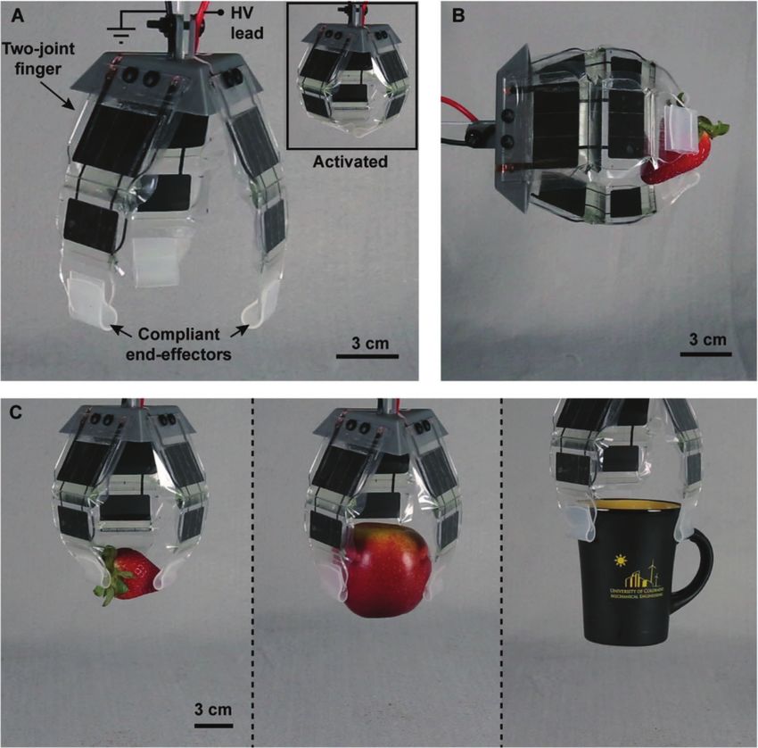
www.advancedsciencenews.com www.advancedscience.com

Figure 8. A three-finger gripper based on series arrangements of SES joints. A) The gripper used three fingers with two joints each. These fingers were
actuated simultaneously to perform gripping tasks. Compliant pads coated with a silicone elastomer increased contact area and friction. The gripper
closed entirely under application of an 8 kV DC voltage (inset). B) SES joints had sufficient mechanical stability to enable horizontal gripping of lightweight
objects such as a strawberry. A voltage of 6 kV was used. C) The compliance of each finger enabled the gripper to grasp a variety of objects without the
need for feedback, including a delicate strawberry (18 g), an apple (170 g), and a ceramic mug (270 g). A voltage of 8 kV was used for all three objects.

gold standard for cm-scale robotic systems; we measured specific of heat in and out of a system, the electrostatic mechanism
torques up to 21.2 N m kg−1 when normalizing to the mass of used in this paper is both fast and scalable to large arrays. SES
the actuator alone (1.36 g). The maximum specific torque across joints also locally displace fluid within the pouch, which avoids
a range of servo motor designs is ≈15 N m kg−1 , independent of the losses and limitations on bandwidth that are introduced
servo size, as demonstrated by Dermitzakis et al.[59] Servo mo- by transporting fluids through supply lines and valves.[79] The
tors have the advantage of high torque output across a large rota- activation and relaxation times of SES joints (12 ms rise, 31 ms
tion angle, but methods for improving the torque output of SES fall) are also substantially reduced compared to curling-type
joints could be explored. These methods include the identifica- HASEL designs (>80 ms rise, >1 s fall)[46] due to the increased
tion of high performance, high permittivity materials, as well as elastic restoring force and reduced flow resistance of the shorter,
scaling principles that increase the specific energy of SES joints segmented pouches used in SES joints. The rich nonlinearities
actuators, similar to ones identified previously for Peano-HASEL observed in the dynamics of SES joints present opportunities for
actuators.[57] Along with these efforts, limitations on scaling of further study, such as the effects of viscosity of the liquid dielec-
actuator size must be investigated in more detail to identify and tric and external load,[62] as well as the elastic restoring force of
expand the useful size range for these electrohydraulic joints the hinge; all of these factors play a role in the dynamic behavior
for adoption toward spider-scale robots.[36] The effects of mate- of SES joints. Modeling efforts, analogous to ones conducted
rial stiffness[57] and instabilities in electrohydraulic actuation[78] for Peano-HASELs,[62] could inform scaling principles for SES
must be characterized and mitigated to ensure robust operation joints to improve dynamic response.
across different length scales. For untethered robots with onboard energy sources (such as
 SES joints are fast, with measured roll-off frequencies of batteries or compressed fluid), high-efficiency actuators enable
24 Hz and activation times as low as 12 ms. Compared to fast, extended operation. The electrohydraulic mechanism on
thermally driven systems,[33,34] which rely on the slow diffusion which SES joints are based has shown efficiencies of 20% in

Adv. Sci. 2021, 2100916 2100916 (12 of 16) © 2021 The Authors. Advanced Science published by Wiley-VCH GmbH
www.advancedsciencenews.com www.advancedscience.com

prototypical systems.[44,46] Further, SES joints exhibit a catch two dielectric polymer films: 1) 18 µm thick BOPP film (5020 film, 70 Ga,
state, which means that they consume little to no power while Multiplastics Inc.) or 2) 20 µm thick polyester film (L0WS, 80 Ga., Mul-
holding an actuation state, with 80× reduced power consumption tiplastics Inc.). Electrodes (CI-2051, Engineered Materials Systems, Inc.)
 were deposited on the films using a screen-printing method. Stiffening lay-
when holding an actuation state versus transitioning between
 ers were made from laser-processed acrylic (Trotec Speedy 360 Flexx, 75W
states. SES joints consumed 140× less power while maintaining CO2 ). The acrylic was 3 mm thick for torque versus angle tests for rigidity,
the same constant torque output when compared to an off-the- and 1.5 mm thick for angle versus voltage tests and all dynamic testing.
shelf servo motor of similar weight; while the large power con- The hinges used in joint characterization were made from adhesive trans-
sumption of the servo was likely attributable to inefficient con- parency, either 75 µm thick or 63 µm thick (Grafix Light Weight Laminating
trol electronics, the design of servo motors does not inherently Film). Adhesive transfer tape (3M, 924) was applied to the stiffening layer
 to attach the actuator. The use of separate transfer tape allowed precise
allow for low power catch states. The inherent catch state of SES
 control over where the actuator was bonded to the joint to prevent over-
joints will aid in creating efficient, multi-DOF robotic systems by constraining the system. Liquid dielectric with viscosities of ≈30 cSt (En-
allowing for minimal power draw from joints that do not actu- virotemp FR3, Cargill) or 5 cSt (silicone oil, 317667, Sigma-Aldrich) was
ate continuously (e.g., stabilizing components). Further, electro- used. The final fill amount was determined by weight according to Table
static actuators can increase apparent efficiencies by implement- S1 of the Supporting Information, and measured with a precision balance
ing charge recovery systems, which have been used previously (Ohaus Adventurer, S05015). Electrical connections to the actuator were
in piezoelectric actuators to recover over 50% of the energy used made with copper tape (1/8”, Oubaka) with the connection reinforced with
 conductive carbon glue (Conductive Carbon Glue 16050, PELCO).
during actuation.[66] Testing Methods: An NI DAQ (Model USB-6212 BNC) took voltage sig-
 SES joints present several additional characteristics that en- nals generated by custom Labview VIs (version 15.0.1f2) or Matlab scripts
courage their use in robotic systems. Compared to traditional (2019b) and fed them into a Trek 50/12 high voltage amplifier. Torque ver-
fluidic actuation, SES joints eliminate the need for fluid lines sus angle measurements were made using a custom test setup with actu-
and control valves, instead replacing them with in-plane electrical ators oriented vertically (Figure S1A, Supporting Information). Torque was
connections that can be easily patterned. The simplicity and in- measured using a load cell (Robotshop RB-SEE-198) via a measurement
 interface (Figure S1B,C, Supporting Information). A Wheatstone bridge
plane design supports the creation of more complex structures by
 (Phidgets PhidgetBridge, 1046_0B) measured the signal from the load
allowing direct integration of actuation at the joint, with minimal cell using a custom python script (Python 3.7). For angle versus voltage,
peripheral components. SES joints could be applied to a variety bandwidth, impulse, and power measurements, angle was measured in-
of articulating robotic designs, leveraging the mechanical com- directly using a laser displacement sensor (Keyence, LK-H057) mounted
ponents inherent to the robotic structure to provide the neces- to a test stand with known geometry to allow transformation of distance
sary support layer for articulation. Further, their electrical opera- to angle (Figure S2, Supporting Information). Laser displacement data for
 frequency tests was recorded at a rate > 50× actuation frequency, while im-
tion is silent and allows for direct electrical-to-mechanical control
 pulse testing used a fixed 5 kHz sampling rate. Power consumption tests
of the actuator output. Control of electrohydraulic systems can used a lightweight servo motor (Pololu #1053, Sub-Micro Servo 3.7 g);
be augmented through closed-loop control methods using exter- servo motor power consumption was measured using the circuit in Figure
nal sensors[80] or even by exploiting their inherent ability to self- S10 of the Supporting Information. The motor was powered using a 5 V
sense deformation states using capacitance measurements.[44,81] benchtop DC power supply (Keysight U8002A) and controlled using the
Finally, the versatile and facile fabrication process presented here PWM signal from a microcontroller (Elegoo Mega 2560) and the “Servo”
enables the creation of SES joints using numerous materials and control library in Arduino (version 1.8.1). An NI DAQ (Model USB-6212
 BNC) sampling at 200 kHz monitored the voltage across both the mo-
geometries for tailored performance. Despite their simplicity, our tor and a 206 mΩ measuring resistor that was used to determine current.
current process for fabrication experienced issues with delami- Power consumption of the SES joint was measured using the circuit in Fig-
nation of the hinge from the stiffening layer during high torque ure S11 of the Supporting Information. A current meter (uCurrent Gold rev.
output at low angles, and after continuous high frequency opera- 2) measured the current provided by the power supply while the voltage
tion. New methods for integrating these layers, including strate- output to the SES joint was measured using the voltage monitor from the
gies for monolithic fabrication[82] could be explored to increase Trek 50/12. Both signals were recorded by an NI DAQ (USB-6212 BNC) at
 10 kHz.
the reliability of joints. Additionally, designs using functionally
 Bidirectional SES Joint: Pouches were 2 × 4 × 1 cm using BOPP film. To
graded stiffness could enable more flexible and robust robotic make the support structure, a two-side adhesive film (Grafix Double Tack
structures.[2,83] Mounting Film) was used as the elastic hinge material. Flexible stiffening
 The family of SES joints introduced here represents a design layers were transparency film with thickness 125 µm (Grafix Heavy Weight
strategy that closely integrates soft actuation with the mechani- Laminating Film). Actuators used conductive mesh tape for the electrodes
cal structure of articulated robotic systems. The result is an elec- attached to the joint (XYZ-axis, 9719, 3M), and an electrically conductive
 hydrogel[84] swelled with LiCl aqueous solution[85] for the outer electrodes,
trically controlled joint with well-rounded performance, capable
 prepared according to Kellaris et al.[57] Actuators were mounted using ad-
of high forces, high speed operation, with low power consump- hesive transfer tape (3M, 924). Since the actuators are not stretchable,
tion in a low-profile design. With continued research, we hope slack was built into the system by biasing the hinge away from the ac-
that SES joints will be versatile building blocks for highly capa- tuator being mounted by 45° before attaching the actuator to the lower
ble spider-inspired robotic systems that feature novel locomotion portion of the support. Bidirectional SES joints were controlled using the
and manipulation capabilities. circuit shown in Figure S12 of the Supporting Information. Optocouplers
 (OC100HG, Voltage Multipliers Inc.) were used to switch HV connections.
 The LEDs of each optocoupler were operated using the circuit presented
 by PetaPicoVoltron.[86] This driving scheme was designed to reverse the
4. Experimental Section polarity of the voltage applied to each actuator during subsequent actua-
 Fabrication of SES Joints: The fabrication method for the electrohy- tion cycles.
draulic components used in this work was modified from a rapid proto- Artificial Spider Limb: The high-voltage electrodes and leads of the
typing method developed by Mitchell et al.[46] Actuators were made from actuators were coated with a 200 µm thick layer of silicone elastomer

Adv. Sci. 2021, 2100916 2100916 (13 of 16) © 2021 The Authors. Advanced Science published by Wiley-VCH GmbH
You can also read