Sputtering onto liquids: a critical review - Beilstein Journals
←
→
Page content transcription
If your browser does not render page correctly, please read the page content below
Sputtering onto liquids: a critical review
Anastasiya Sergievskaya‡1, Adrien Chauvin‡1,2 and Stephanos Konstantinidis*,‡1

  Review                                                                                                                          Open Access

  Address:                                                             Beilstein J. Nanotechnol. 2022, 13, 10–53.
  1Plasma-Surface Interaction Chemistry (ChIPS), University of Mons,   https://doi.org/10.3762/bjnano.13.2
  23 Place du Parc, B-7000 Mons, Belgium and 2Department of
  Condensed Matter Physics, Faculty of Mathematics and Physics,        Received: 28 July 2021
  Charles University, Ke Karlovu 5, 121 16 Praha 2, Czech Republic     Accepted: 07 December 2021
                                                                       Published: 04 January 2022
  Email:
  Stephanos Konstantinidis* - stephanos.konstantinidis@umons.ac.be     Associate Editor: P. Leiderer

  * Corresponding author   ‡ Equal contributors                        © 2022 Sergievskaya et al.; licensee Beilstein-Institut.
                                                                       License and terms: see end of document.
  Keywords:
  low-pressure plasmas; magnetron; nanoparticles; nanoparticle
  formation; sputtering; sputtering onto liquids

Abstract
Sputter deposition of atoms onto liquid substrates aims at producing colloidal dispersions of small monodisperse ultrapure nanopar-
ticles (NPs). Since sputtering onto liquids combines the advantages of the physical vapor deposition technique and classical
colloidal synthesis, the review contains chapters explaining the basics of (magnetron) sputter deposition and the formation of NPs
in solution. This review article covers more than 132 papers published on this topic from 1996 to September 2021 and aims at pro-
viding a critical analysis of most of the reported data; we will address the influence of the sputtering parameters (sputter power, cur-
rent, voltage, sputter time, working gas pressure, and the type of sputtering plasma) and host liquid properties (composition, tem-
perature, viscosity, and surface tension) on the NP formation as well as a detailed overview of the properties and applications of the
produced NPs.

Introduction
According to the general terminology, nanoparticles (NPs) are            recipes of NP synthesis allowing one to prepare stable colloidal
objects that have a size of less than 100 nm. Because of the size        solutions of monodisperse NPs. However, not all published syn-
effects, NPs have unique properties that allow them to be used           thetic procedures are suitable for the upscaled production due to
as components of advanced materials for a wide range of appli-           poor reproducibility or difficult purification processes [4,5].
cations such as optics, catalysis, or biomedicine [1-3]. Since the       Indeed, some applications require the usage of components with
properties of NPs strongly depend on their size, size distribu-          specific purity. Purifying the colloidal solutions from the
tion, shape, composition, and the composition of surrounding             by-products is an additional, time-consuming, and expensive
media, it is extremely important to control these parameters.            step in the production chain that might cause detrimental issues,
Nowadays, an interested reader can find thousands of different           for example, NP aggregation. In this respect, low-pressure

                                                                                                                                            10
Beilstein J. Nanotechnol. 2022, 13, 10–53.

plasma-based sputtering onto liquids (SoL) is a relatively new               field of research still does not have a well-established termi-
synthetic approach in which the purification step can be                     nology, some works were found only by monitoring the cita-
avoided. This technique is based on the sputtering of metallic or            tions of important pioneering works [10-12]. The next chal-
ceramic targets over a host liquid substrate that sustains low               lenge after collecting the material was to make a direct compari-
pressures (typically in the range between 10 −4 to 10 −3 and                 son of the published data. Quite often, some essential experi-
1–10 Pa). Because (i) the target material has a high purity and              mental parameters were missing. These two problems come
(ii) the host liquid plays the role of solvent and protective agent          from the main feature of the SoL approach: It is the combina-
for growing NPs, the approach got a reputation of a method                   tion of a plasma-based technique and colloidal synthesis. There-
permitting the production of ultrapure monodisperse NPs with-                fore, researchers from both communities are involved and
out additional stabilizing and reducing reagents. Despite the fact           physicists quite often do not pay enough attention to the sol-
that low-pressure plasma-based sputtering is known since 1852                vent properties, while chemists may have little or no know-
and widely used in industry [6-8], the SoL approach is not a                 ledge of plasmas and plasma–surface interactions. For this
well-established field yet (Figure 1). In 1974, Yatsuya et al.               reason, we first briefly introduce the theoretical background of
used a liquid as a substrate during a physical vapor deposition              plasma-based sputtering and a short overview of the formation
(PVD) experiment. They thermally evaporated metals in                        of metal NPs in liquid media.
vacuum onto silicon oil for NP production [9]. After the
pioneering experiments of Yatsuya et al., depositions onto                   This critical review aims to describe the scientific state of
liquids were not mentioned in research papers for almost                     the art of SoL and to eliminate the misunderstanding of
20 years until 1996 when two research groups reported SoL ex-                physicochemical basics of this technique. For this purpose, a
periments. Ye et al. studied the formation of silver films on the            presentation of the underlying processes leading to NP produc-
surface of silicon oil [10] while Wagener et al. prepared silver             tion is first provided. This part is constituted of a brief introduc-
and aluminium NPs by deposition onto silicon oil using various               tion to (i) sputtering and (ii) the kinetics of NP nucleation and
experimental conditions [11]. Afterward, Torimoto et al. used a              growth in solutions. Then, the specific mechanism of NP pro-
sputter coater for the synthesis of small gold (Au) NPs by sput-             duction by SoL is discussed based on the detailed analysis of
tering an Au target onto a thin layer of an ionic liquid (IL) [12].          the effect of various experimental parameters on the size of NPs
This paper [12] published in 2006 initiated a series of similar              and their colloidal and oxidation stability in host liquid
works in several labs which, were focused on the deposition of               matrices. Furthermore, a carefully structured overview of all
various metals onto low vapor pressure liquid substrates                     types of products produced by SoL is presented including
[13,14]. Careful analysis of the literature data has shown that              monometallic and alloy NPs, oxide NPs, thin films, and nano-
about 132 research papers were published on the SoL topic                    composites and their promising optical, luminescence, and cata-
since 1996 (Figure 1). It should be noted that, since the SoL                lytic properties.

 Figure 1: Growth of research interest in the SoL approach. Insert: Number of SoL-related publications in the period of 1996–2021.

                                                                                                                                                   11
Beilstein J. Nanotechnol. 2022, 13, 10–53.

Review                                                                     further drawback is the large consumption of energy to main-
1 Theoretical background                                                   tain the required pressure and temperature conditions used in
1.1 Techniques available for the synthesis of NPs                          the synthesis procedures. The most common physical methods
The mass production of NPs with controlled physicochemical                 used to generate NPs are high-energy ball milling, laser abla-
characteristics is required for their applications in various fields       tion, electrospraying, inert gas condensation, PVD, laser pyroly-
on the industrial scale [15]. Generally, methods employed for              sis, flash spray pyrolysis, and melt mixing [16].
the synthesis of NPs follow either the “top-down” or the
“bottom-up” routes. On the one hand, in the “top-down” ap-                 Chemical methods are the traditional and most widely used ap-
proach, a destructive technology is employed. The production               proaches for the synthesis of colloidal NPs. In this case, molec-
starts from bulk materials that leach out systematically, leading          ular and/or atomic species are transformed into NPs. A typical
to the generation of NPs. The starting material can be reduced             procedure involves the growth of NPs in a liquid medium
in size using either a physical or a chemical route. On the other          containing various reagents, particularly precursor species,
hand, the “bottom-up” approach, or self-assembly, refers to                reducing agents, and stabilizing agents to prevent the aggrega-
building up a structure atom-by-atom or molecule-by-molecule               tion of NPs in the reaction mixture. Generally, the chemical
through a chemical or biological engineering procedure. In                 methods are low-cost and allow one to produce large quantities
these synthesis approaches, the building blocks are initially              of NPs; however, a couple of drawbacks can be highlighted and
formed and assembled into the final NPs. Therefore, NP synthe-             include contamination from precursor chemicals, use of sol-
sis methods can be divided into three groups: (i) physical                 vents, and generation of sometimes hazardous by-products.
methods, (ii) chemical methods, and (iii) bio-assisted methods             These chemical methods can be divided into two major tech-
[16-18]. An overview of the different approaches used in the lit-          niques, namely chemical vapor deposition (CVD) with liquid-
erature for the synthesis of NPs is reported in Figure 2. For              phase synthesis and colloidal synthesis. In general, the colloidal
more detailed information on the methods and techniques avail-             synthesis of NPs is highly acclaimed due to its versatility [16].
able for the creation of NPs, dedicated reviews are available
[16-21].                                                                   So-called bio-assisted methods, biosynthesis, or green synthe-
                                                                           sis also attract the attention of many researchers due to the “en-
Physical methods are based on physical transformations of                  vironmentally friendly” nature of these processes, promoted by
matter. These methods mainly operate with a “top-down”                     involving biological systems or by being related directly to bio-
strategy where bulk materials are reduced in size, down to the             logical systems [20,23]. These methods use, among others,
nanoscale, via their interaction with photons, heat, or ions or via        bacteria, fungi, viruses, yeasts, and plant extracts to synthesize
mechanical milling. Those methods are valuable as they are free            NPs. Although bio-assisted procedures are very promising, the
from solvent contamination [16]. However, the production rate              major problem is the reproducibility of the processes. Besides,
is relatively low, and the cost of production is very high, mainly         the exact mechanisms underlying the NP formation using green
due to the massive waste produced during the synthesis [22]. A             plant extracts have not been elucidated yet. Finally, their large-

 Figure 2: Summary of the different types of synthesis methods to produce NPs.

                                                                                                                                             12
Beilstein J. Nanotechnol. 2022, 13, 10–53.

scale use is limited by the presence of undesired contaminants,                 atoms from a surface bombarded by fast particles such as noble
such as fragments of biological materials, which require                        gas cations. These ions can be produced in a low-pressure
complicated, expensive, and time-consuming purification pro-                    plasma and accelerated towards a negatively biased surface, that
cedures. Bio-assisted methods can be divided into three cate-                   is, the cathode of the system. A typical vacuum chamber used
gories according to the system used: (i) microorganisms,                        for coating deposition by sputtering is presented in Figure 3a
(ii) biomolecules, and (iii) plant extracts [23].                               where the key elements are presented: the negatively biased
                                                                                cathode covered by the target, that is, the source of atoms, the
Besides bio-assisted methods, which are a promising approach                    sample to be coated, the pumping system, the pressure gauge,
but not well adapted for mass production yet, both chemical and                 the electric power supply, and the gas inlets.
physical processes have their advantages and can be comple-
mentary. On the one hand, chemical synthesis is very versatile                  Sputtering processes have been studied and developed for a
in controlling NP size while the chemical purity of the NPs is                  long time [7,8] and have been implemented in the coating
limited mostly by the stabilizing agent used. On the other hand,                industry to deposit nanometer-scale films onto various solid
physical methods are very clean methodologies to produce NPs,                   substrates. Such functional coatings must have tailored physico-
and the chemical purity of the materials produced is close to                   chemical properties to fit the targeted application in fields such
that of the starting bulk material. By combining both ap-                       as mechanics, optics, electronics, and biomaterials. Various
proaches, SoL takes advantage of both techniques and allows                     types of coatings can be produced, from pure metals to metal
for the production of NPs with controlled size, shape, and purity               oxides, nitrides, carbides, oxynitrides to metal alloys, or chemi-
[13].                                                                           cally more complex combinations such as high-entropy alloys
                                                                                [24,25]. Also, the micro/nanostructure of the films is a very im-
The next parts of this section are dedicated to the detailed de-                portant aspect of the tailoring, and the sputtering process
scription of processes involved in the SoL process, namely the                  usually allows for controlling coating density, crystallinity, and
sputtering process and colloidal synthesis.                                     micro/nanostructure to some extent by carefully varying the
                                                                                working parameters. For instance, energy transferred from the
1.2 Introduction to sputtering                                                  plasma to the film during growth through heating of the sub-
In this chapter, we introduce the basic physical mechanisms                     strate and/or via bombardment by energetic particles or post-
involved in the sputter deposition of materials and related pro-                deposition annealing of the film can be envisaged. More infor-
cesses. Low-pressure plasma-based sputter deposition, along                     mation on thin film deposition (onto solid substrates) by sput-
with evaporation, cathodic arc, or laser-based deposition,                      tering-based processes can be found in books such as [26-31].
belongs to the family of PVD techniques, which have been orig-
inally designed to coat objects with thin film materials. Sput-                 Commercial table-top sputter coaters can be found, for example,
tering is the physical phenomenon describing the ejection of                    in electron microscopy facilities and are part of the sample

 Figure 3: (a) Schematic representation of a (magnetron) sputtering deposition chamber along with some key setup components. Sputtered target
 atoms are represented in gold color while argon ions (Ar+) and argon neutrals (Ar) are shown as black and white dots, respectively. Plasma electrons
 are not shown. Some particles have their trajectories highlighted by black arrows. Magnetic field lines are drawn as dashed, arc-shaped, black lines in
 the vicinity of the target surface. The sample is a solid. (b) Four variations of the MS process for the deposition of multielement thin films. The deposi-
 tion of a binary coating, containing elements A (yellow) and B (black), is presented. The substrate is a liquid.

                                                                                                                                                           13
Beilstein J. Nanotechnol. 2022, 13, 10–53.

preparation protocol. They are used to coat the sample with a         to present the deposition rate as a flux of particles or a mass
conductive material to facilitate the observation. These devices      deposited onto the liquid surface per unit time.
usually come with a limited number of variable parameters.
Customized vacuum chambers dedicated to the detailed study            The sputtering process itself is characterized by the so-called
and development of this particular type of PVD process are also       ion-induced sputtering yield, which represents the probability of
available in research laboratories. Sputtering has become             sputtering a given number of target atoms for one incident
industry-relevant since permanent magnets were set inside the         plasma ion. The plasma ion (e.g., Ar+), accelerated towards the
cathode body, underneath the target, to generate a magnetic           surface of the sputter target by the negative potential applied to
field in the target vicinity thus promoting magnetron sputtering      the cathode, transfers its momentum to the surface atoms, which
(MS) cathode systems. Typical MS cathodes consist of a                are expelled out of the surface, that is, sputtered. More informa-
magnet placed at the center of the target and magnets with            tion about the theory of ion-induced sputtering can be found in
opposite poles on the target periphery. This configuration is         [8]. Ion–surface interaction and sputtering yield data can be
schematically presented in Figure 3a, along with some typical         calculated using codes such as SRIM [35] and TRYDIN [36],
variations (Figure 3b) that allow to further extend the possibili-    while transport of the sputtered species through the gas phase
ties towards the deposition of multielemental coatings. In            and subsequent film growth can be computed using, for exam-
Figure 3b, the deposition of elements A and B is depicted but         ple, SIMTRA [37] and NASCAM [38] codes, respectively. The
the deposition processes can be further upgraded to include           evolution of the sputtering yield calculated by SRIM for carbon
three cathodes (or more) or to perform co-sputtering with two         (C), titanium (Ti), and Au targets as a function of the kinetic
alloy targets to deposit coatings containing, for instance, four      energy of the bombarding argon ions is presented in Figure 4.
different elements. Industrial-sized coaters, especially in the       The kinetic energy of the argon ions ranges from 100 to
optical coating industry, rely on several meter-long rotating         1100 eV, which are typical values for MS discharges. For the
cylindrical targets [32].                                             calculation, ions are assumed to impinge the surface at normal
                                                                      incidence and the thickness of the target is set to 1 µm. The
In MS configuration, the combined magnetic and electric fields,       sputtering yield values are averaged over 5000 ion impacts. The
the latter being generated by the negative voltage applied to the     sputtering yield is influenced by the surface binding energy (Eb)
cathode, allow for trapping the plasma electrons near the target      of the target material, here Eb = 7.41, 4.89, and 3.8 eV for car-
surface to enhance gas ionization in that region. Consequently,       bon, titanium, and gold, respectively. These values are provi-
the ion flux towards the target and the corresponding cathode         ded by the SRIM code.
current is significantly increased as compared to a diode glow
discharge ignited without inserting magnets. In the case of MS        Atoms leaving the target surface have an average kinetic energy
systems, the discharge current I scales exponentially with the        of the order of a few electronvolts [39-41]. This is a higher
applied voltage V, as highlighted by the equation I = k·V n ,         value than atoms produced during evaporation-based processes,
where k and n depend on the magnetron cathode and other               whose energy is in the range of the thermal energy of the body
process parameters as discussed in [33,34] while n is an indica-      that is heated and evaporated, that is, a fraction of an electron-
tion of the electron-trapping efficiency.                             volt. Sputtered atoms may collide with plasma atoms and lose
                                                                      their energy before reaching the neighboring surfaces onto
Since the discharge current is dramatically increased because         which they condense. The collision rate and the fraction of the
the ionization efficiency of the gas is augmented, the gas pres-      kinetic energy they dissipate in the gas phase mainly depend on
sure can be substantially decreased, typically in the millitorr       the product of pressure times the distance traveled. Typically,
(roughly pascal) range, as compared to conventional diode             the pressure lies in the range of pascals while the distance be-
discharges. In turn, lowering the working pressure while              tween the target and the substrate is of the order of several
keeping a high discharge current density, that is, a few tens of      centimeters. Ultimately, these atoms may be thermalized if the
millamperes per square centimeter, allows for increasing the          number of collisions is high and the atoms land on the surface
target erosion rate and facilitates the transport of the sputtered    with a kinetic energy of the order of the gas temperature (ca.
atoms towards the substrate as gas-phase scattering is mini-          1/40 eV). Condensation enthalpy is released as atoms land on
mized. The film deposition rate, lying typically in the range of      the surface and heat the substrate. Besides condensation, energy
several nanometers per minute, is therefore higher compared to        is also provided to the surface by other plasma species such as
non-magnetized sputtering discharges. Here a remark should be         ions, electrons, (fast) neutrals, and photons whose fluxes may
made: While the film growth rate is usually expressed in units        vary in accordance with the process conditions [42]. It should
of thickness per unit time (e.g., nanometers per minute) in sput-     be mentioned that the surface of the sputter target, whose tem-
tering-related publications, in the case of SoL, it might be better   perature is gradually increasing because of ion bombardment,

                                                                                                                                        14
Beilstein J. Nanotechnol. 2022, 13, 10–53.

 Figure 4: SRIM calculation of the sputtering yield of C (black disks), Ti (grey squares), and Au (white triangles) targets by argon ions. The lines are a
 guide to the eye.

emits IR photons. This radiation is detected at the substrate                   taining the liquid, during the plasma ON and OFF times. The
location and contributes to an increase of the substrate surface                liquid is heated by the sputtering plasma and cooled by the
temperature as well [43]. In the case of reactive sputtering (dis-              emission of radiation. Values of the liquid temperature reached
cussed below), the formation of chemical bonds between, for                     after 1800 s of plasma ON time are reported in [48] for a
instance, oxygen and deposited metal atoms, may occur and                       power density of 4 W/cm2 applied to the magnetron cathode.
contribute to the increase of the amount of heat released on the                The argon plasma (0.07 Pa) is used to sputter a 5 cm in
surface, too. Thornton reported a substrate temperature in the                  diameter copper target. The liquid is placed 10 cm away
range of 150 °C when measuring heat fluxes during magnetron                     from the target. The red arrow on the thermograms highlights
sputter deposition processes [44]. In Thornton’s report, the                    the presence of a cross-over point when the temperature
probe used for the heat flux measurement, whose temperature                     gradient is reversed during the cooling period (plasma OFF).
increases when submitted to the sputtering plasma, was a stain-                 The heating of the liquid as well as the presence of a tempera-
less-steel body weighing 200 mg. Ultimately, in the case of a                   ture gradient might influence the physicochemical properties of
solid substrate, the heat transfer and resulting increase of sur-               the host liquid and the transport of matter inside the liquid me-
face temperature will influence the film growth mechanism and                   dium.
coating properties such as microstructure and phase constitu-
tion, as emphasized in [45,46]. Depending on the process condi-                 It is possible to sputter two or more elements simultaneously by
tions, energy flux values span from a few tens to thousands of                  setting up the sputtering apparatuses identical to the one
milliwatts per square centimeter at the substrate position                      presented in Figure 3 with segmented, alloy, or pressed powder-
[42,47]. In the case of the SoL process, the abovementioned                     based targets [49,50]. However, one should pay attention to the
contributions may also impact the liquid temperature but also its               fact that the elemental composition of the deposited material
physicochemical properties as plasma electrons, ions, and radia-                might not be identical to the elemental composition of the
tion may induce, for example, bond breaking in the liquid mole-                 sputter target. Various phenomena may intervene here such as a
cules.                                                                          difference in the scattering efficiency for the various sputtered
                                                                                atoms transported in the gas phase and different sputter yields,
In Figure 5, we report some of our experimental data regarding                  ultimately leading to the abovementioned composition discrep-
the heating of the host liquid when the latter is submitted to a                ancies between the source and the deposited material. The inter-
MS plasma [48]. The temperature of 4 mL of castor oil was re-                   ested reader might refer to articles that exemplify this discus-
corded by inserting two thermocouples at two different posi-                    sion such as [51-53]. On the other hand, co-sputtering pro-
tions inside the cup (3 cm in height and 1.25 cm in radius) con-                cesses involve two or more cathodes inside the vacuum cham-

                                                                                                                                                             15
Beilstein J. Nanotechnol. 2022, 13, 10–53.

 Figure 5: (a) Evolution of the castor oil (4 g) temperature as a function of time, at 5 and 10 mm from the bottom of the container. Copper is sputtered
 by applying 4 W/cm2 to the cathode. Argon pressure equals 0.07 Pa. The topmost probe records a higher temperature than the probe located deeper
 inside the liquid during the plasma ON time. The red arrow highlights the presence of a cross-over point during the cooling period, that is, plasma
 OFF, when the temperature gradient is reversed. (b) Schematic drawing (not to scale) showing the positions of the two probes inside the container.
 Sputtered copper atoms are shown as well.

ber; the electrical power applied to each cathode independently                ample, a few nanometers thick layer of AlOx will cover an alu-
controls the flux of each sputtered atoms and, hence, the chemi-               minum (Al) target surface when it is sputtered in an Ar/O2 at-
cal composition of the coating. Here again, extra care should be               mosphere. This rather complex phenomenon named target
taken regarding the elemental composition of the deposited ma-                 poisoning has been discussed and modeled in, for instance, [57-
terials as it might depend on the position where the elemental                 60]. The value of the critical reactive gas flow depends on pa-
analysis is made on the substrate, especially if a spatially                   rameters such as the volume of the deposition chamber and the
resolved analysis is carried out by a technique such as scanning               system pumping speed, the electrical power applied to the
(transmission) electron microscopy combined with energy-                       target, the chemical nature of the sputtered material, and the
dispersive X-ray spectroscopy (S(T)EM-EDS). Typical exam-                      molecular gas.
ples of the formation of compositional gradients on coated sur-
faces can be found, for example, in [54,55]. Further control on                Before reaching the critical value, the number of reactive
film chemistry is obtained through reactive (magnetron) sput-                  species detected in the gas phase is close to zero because the
tering. In this case, the metallic target is sputtered by a plasma             sputtering and subsequent deposition of metal atoms on the
generated in a mixture of argon with a molecular gas, by using                 chamber walls acts as an auxiliary pumping system for the reac-
dedicated mass flow controllers (MFC). Oxygen, nitrogen,                       tive gas species. This so-called getter effect is efficient for
methane, or hydrogen sulfide can be added to deposit metal                     metals having a strong affinity for the reactive gas, as in the
oxides, nitrides, carbides, or sulfides, respectively. One exam-               case of the Al–O combination. As the target gets poisoned, the
ple of such tailoring of the film chemistry is reported in [56]                partial pressure of reactive gas increases abruptly [61] as evi-
where zinc (Zn) and tin/copper (Sn/Cu) targets are both co-sput-               denced by plasma analysis [62]. Also, the ion-induced second-
tered in a reactive H2S/Ar reactive plasma for the synthesis of                ary electron emission yield (ISEE) of the target in its metallic
Cu2ZnSnS4 (CZTS) coatings. In the case of reactive sputtering,                 and poisoned states are different. So-called secondary electrons
MFCs manage the flow (usually expressed in standard cubic                      are electrons emitted by the surface when the latter is
centimeters per minute, sccm). This is a key aspect of the reac-               bombarded by fast particles such as ions. If more (or less) sec-
tive process because in most cases, for a critical value of this               ondary electrons enter the plasma, the ionization rate of the
parameter, the discharge current and voltage, the partial pres-                plasma particles and therefore the ion current at the cathode in-
sure of the reactive gas, and the flux of deposition change sig-               creases (or decreases). From a practical point of view, if the
nificantly, sometimes abruptly. When this critical value is                    power supply used to generate the plasma is set to keep the dis-
reached, the interaction of the reactive gas molecules and atoms,              charge current or the discharge power constant, the voltage will
ionized or not, present in the plasma leads to the formation of a              be adapted as the target surface chemistry and the ISEE change.
layer of compound material on the surface of the target. For ex-               Besides, once the poisoned regime is reached, compound mole-

                                                                                                                                                       16
Beilstein J. Nanotechnol. 2022, 13, 10–53.

cules can be sputtered as demonstrated by mass spectrometry        some extent. The kinetic energy of the film-forming species is
analysis of the plasma ion chemistry during the reactive sput-     critical when depositing thin films deposited on a solid sub-
tering of Ti in Ar/N2 [63] or in Ar/O2 plasmas [64]. In these      strate. Most likely, it also plays a critical role when a liquid sub-
publications, besides Ti+, molecules such as TiN+ or TiO+ and      strate is used. More information on HiPIMS discharges can be
TiO2+ but also reactive gas molecules, atoms, and ions (N2,        found in [70-72].
N2+, N+) were detected in the gas phase. Interestingly, AuO
molecules were observed when sputtering Au in an Ar/O2 mix-        The abovementioned variations of the plasma characteristics,
ture [65], highlighting the rich gas-phase chemistry of sput-      which, in turn, impact the plasma–surface interaction, can be
tering plasmas. Finally, as target poisoning occurs, the deposi-   monitored by ad hoc plasma analysis measurements as de-
tion flux is found to decrease, sometimes by one order of mag-     scribed in [73-76].
nitude or more as reported in [60].
                                                                   This section highlights that various process parameters can be
It should be noted that various kinds of electric waveforms can    varied during a sputtering experiment to manipulate the charac-
be applied to the cathode to generate the plasma and induce        teristics of the plasma and tailor the plasma–(liquid) surface
sputtering. Direct current (DC), radio frequency (RF, usually at   interaction to, ultimately, control the characteristics of the NP.
13.56 MHz), pulsed-DC, or high-power pulses can be applied.        Although the external control parameters such as pressure and
Typically, RF generators are employed when a dielectric target     sputter power may influence simultaneously several plasma
is to be sputtered. Pulsed-DC discharges are generated when a      characteristics and induce sometimes non-linear phenomena,
metallic target is sputtered in a reactive atmosphere to synthe-   one can nevertheless highlight some general trends: (i) The
size insulating compounds [66]. This situation may lead to         nature of the target materials (e.g., the combinations of differ-
unwanted arcing events on the target surface, which are detri-     ent targets or the fact that the target is made of an alloy, see
mental to the discharge stability and deteriorate the quality of   Figure 3b), and/or the implementation of reactive sputtering by
the deposited film because large particles can be emitted from     adding a molecular gas (e.g., N 2 , O 2 and CH 4 ) allow for
the target surface. Such pulsed-DC discharges, which some-         depositing a very large catalog of materials ranging from pure
times also make use of bipolar waveforms, allow for                metals and alloys to metal oxides, nitrides, and other com-
discharging the dielectric layer grown on the target surface       pounds. (ii) The product of pressure times target–substrate dis-
during the OFF time and allow for safe operation, see [67] for     tance and the electrical power applied to the cathode controls
more information. High-power plasma pulses can be applied as       the deposition flux. The precision achieved in controlling the
well on the cathode. The goal is to apply a very high peak cur-    thickness of films deposited on a solid substrate is typically in
rent pulse without overheating the target material and             the nanometer range. The deposition rate is very stable over
destroying the underlying magnets. By applying such a very         time. (iii) The product of pressure times target–substrate dis-
high voltage in a short duration of time, from a few tens of       tance, the sputter power, the type of power supply utilized (DC
microseconds up to a few milliseconds, at a proper repetition      vs HiPIMS plasmas), and the pressure and the nature of the
frequency to allow the time-averaged power to be comparable        gases utilized to generate the plasma control the energy deposi-
to that applied in other discharge types, one can dramatically     tion and, more specifically, the fluxes of particles reaching the
increase the plasma electron density. As a result, in such high-   liquid surface. Amongst the species that may play a role in NP
power impulse magnetron sputtering (HiPIMS) discharges, the        formation are (1) atoms/molecules such as Ar neutrals, Ar
ionization degree of the sputtered metal atoms is significantly    metastables (Ar atoms have metastable states lying at 11.6 eV),
increased. Typically, under these conditions, the sputtered        sputtered metal atoms, and molecules such as N 2 or O 2 if
species have a higher kinetic energy, and coating properties (on   reactive sputtering is implemented; (2) ions such as Ar+, metal
solid substrates) are changed as compared to DCMS discharges.      ions (M + ) but also sometimes multiply charged ions (Ar 2+ ,
The film crystallinity can be promoted at lower growth temper-     M2+). If the plasma is generated in an argon/reactive gas mix-
atures, although sometimes, a too intense ion bombardment may      ture R+, R2+, R2+, and MRx+ ions (with R being, e.g., O or N)
lead to the amorphization of the material [68]. Because they are   can also be found; (3) chemically reactive radicals such as O or
ionized, the kinetic energy of the film-forming species can also   N atoms produced through dissociation reactions during reac-
be tuned by applying an electric bias voltage onto the substrate   tive sputtering. O atoms can also originate from dissociated
during growth. More recently, bipolar HiPIMS (B-HiPIMS) dis-       H2O or O2 molecules present in the chamber if the quality of
charge has been implemented. A positive voltage pulse is           the vacuum is not good; (4) electrons and photons, with ener-
applied after the negative pulse generated to sputter and ionize   gies spanning from the hard UV up to the IR domain, may
the metal atoms [69]. The kinetic energy of the film-forming       eventually promote bond breaking of the liquid host molecules
species can thus be controlled by the positive pulse voltage to    and heating.

                                                                                                                                       17
Beilstein J. Nanotechnol. 2022, 13, 10–53.

Researchers working with the sputter deposition process should        know today, is not accurate since NPs and especially their
be aware of these “control knobs” to ultimately control the NP        nuclei have a different surface free energy [77]. The mecha-
formation during the SoL approach.                                    nism of sulfur (S) sol formation proposed by La Mer includes
                                                                      the formation of monomers, S2 (Equation 1), their burst homo-
1.3 Formation of NPs in solutions                                     geneous nucleation (Equation 2), and the subsequent diffusive,
Colloidal synthesis, which is also called the “classical wet          agglomerative growth (Equation 3):
chemical approach”, is one of the well-studied methods to
produce NPs with desired size, shape, and composition [2].                                                                              (1)
Colloidal synthesis allows one to obtain metal, oxide, halide,
chalcogenide, and other types of NPs but the mechanisms of                                                                              (2)
their formation are different, even though all of them include an
initial nucleation step followed by a growth step [77]. In this                                                                         (3)
chapter, we will concentrate on the formation of metal NPs in
solutions because, up to June 2021, the vast majority of NPs          As one can see in Figure 6a, the La Mer mechanism can be de-
produced by the SoL technique has been metallic [13,14,78].           scribed by a succession of three phases. Phase I is a rapid
                                                                      increase of monomer (S2) concentration in the reaction solution.
As it was described in section 1.1, four components are               Phase II is an extremely fast nucleation process via a stepwise
normally needed for the colloidal synthesis of metal NPs: (i) the     sequence of S2 monomer additions until the formation of nuclei
metal precursor, usually a salt such as HAuCl4, is chemically         having a critical size is reached. Since La Mer worked in a
reduced by a (ii) reagent (e.g., sodium citrate, sodium borohy-       frame of statistical mechanics, the nucleation step can occur
drate, ascorbic acid, glucose, hydrazine, or various amines) in       only in supersaturated solutions, when the probability of en-
the presence of a (iii) stabilizing agent (e.g., organic thiols,      counters between monomers is high. After the formation of the
amines, acids, or various surfactants, i.e., compounds having         first nucleus, the monomer concentration falls below supersatu-
active groups with S, N, or O atoms) in the chosen (iv) solvent       ration and new nuclei cannot be formed. Phase III is the further
[2,79]. The number of reagents might be less than four when the       growth of the particles limited by the diffusion of the mono-
reduction process is initiated by light, when the reducer mole-       mers to the nuclei surface. The assumption that burst nucle-
cules protect the obtained NPs, or when the solvent plays either      ation significantly reduces the concentration of monomers
the role of the reducer or the stabilizer [79]. The final amount of   allows for achieving the key separation of the nucleation and
NPs in the solution and their final size depend on the kinetics of    growth steps, which is a mandatory condition for the formation
NP formation and, mainly, on the ratio between the rates of nu-       of monodisperse particles (but it can be achieved in the frame of
cleation and growth steps [77]. The stability of obtained NPs         other models). The readers interested in CNT and mathematical
depends on many factors but the affinity of the stabilizer            equations behind the La Mer model [86] are referred to the
reagent to the NP surface plays a leading role [79].                  reviews in [80,83,85].

Two main models have been actively used to describe the for-          For almost 50 years, La Mer's pioneering mechanism was the
mation of primary metal NPs, namely the La Mer model and the          only available mechanism that explained the formation of
autocatalytic model [80]. Even though both models were pro-           monodisperse particles and provided a mathematical model for
posed decades ago, the colloids community is still arguing            fitting the kinetic curves [89]. As a result, it was applied to any
which one is better [81-85]. La Mer and Dinegar proposed a            colloidal system, including colloidal dispersions of metal NPs,
theory describing the formation of monodispersed sulfur               and finally was considered as “overcited” [90]. In reality, this
hydrosols in 1950 [86]. Two years later, La Mer published a           mechanism describes very well the formation of sulfur sols and
critical work on nucleation theory applied mostly to the forma-       analogous systems, for example, AgCl, BaSO4, and TiO2 NPs
tion of sulfur and barium sulfate sols [87]. It is important to       [85,91].
highlight here that the La Mer model was not built based on ex-
perimental observations about the formation of metal NPs.             The main problem of generalizing the La Mer mechanism to
Basically, La Mer and co-workers applied classical nucleation         other systems is that homogeneous nucleation does not always
theory (CNT; this abbreviation was widely used by colloidal           take place in a supersaturated solution [89]. For example, transi-
chemists years before carbon nanotubes became a hot research          tion-metal NPs can nucleate and grow from diluted solutions
topic) that was developed by Döring and Becker in 1935 [88]. It       [77] as shown for the first time by Turkevich in 1951 [92].
is worth noting that CNT treats nuclei as fragments of the bulk       Turkevich and co-workers studied the reduction of HAuCl4 by
phase having the same macroscopic properties. This, as we             citrate anions (which also plays the role of a stabilizer for the

                                                                                                                                         18
Beilstein J. Nanotechnol. 2022, 13, 10–53.

 Figure 6: Schematic diagrams representing the NP formation as a function of time: (a) La Mer model and (b) autocatalytic model.

Au NPs) at different temperatures and different reagent concen-             become nuclei of the final NPs [94,95]. Because silver clusters
trations [92]. By means of transmission electron microscopy                 absorb light at different wavelengths than the surface plasmon
(TEM), it was shown that the Au sol formation process consists              resonance (SPR) band of Ag NPs (which is used for monitoring
of an induction period followed by a rapid increase in the num-             of NP growth kinetics by UV–vis spectroscopy) one can spot
ber of particles, followed by a linear increase, followed by a              the induction period on the sigmoidal kinetic curves. Note-
rapid decrease in the growth rate. In other words, the typical              worthy is the important contribution by Huang et al. [96], who
kinetic curve has a sigmoidal S-shape (Figure 6b). Turkevich                proved the autocatalytic nature of NP growth by an easy experi-
and co-workers proposed an “organizer” nucleation theory, ac-               mental test. They introduced Ag NPs to a solution containing
cording to which the Au ions are bound together by an “orga-                Ag ions and a reducer. This led to a significant increase in the
nizer” (citrate ion) into “copolymers” [92]. Unfortunately, the             process rate due to the reduction of Ag ions on the NP surface.
authors did not formulate a clear detailed mechanism of the
process describing the underlying, kinetically dominant,                    In 1997, Watzky and Finke published a fundamental work,
elementary steps. So, their “organizer” theory looked very                  which included a simple mechanism describing the formation of
complicated as compared to the simpler La Mer mechanism. As                 metal NPs in diluted solutions, a kinetic model, and a set of
a result, the work [92] had been cited scarcely until the produc-           mathematical equations that allowed one to process the kinetic
tion of Au NPs became a hot research topic. The reduction of                data [89]. They suggested a two-step mechanism, which
Au ions by sodium citrate was also studied by Takiyama in                   consists of a slow, continuous nucleation (Equation 4) and a fast
1958 [93]. He noticed that (i) the process starts with an induc-            autocatalytic surface growth (Equation 5):
tion period followed by rapid nucleation, (ii) the number of par-
ticles does not change after the nucleation, and (iii) particles                                                                                  (4)
grow by an autocatalytic reaction on the nuclei surface, that is,
the surface atoms of the metal NPs reduce the metal ions
present in the solution and, thus, NPs grow further. Takiyama                                                                                     (5)
used empirically chosen mathematical equations to fit the ob-
tained kinetic curves and calculated rate constants under differ-
ent conditions. However, he did not formulate a step-by-step                According to the Finke–Watzky model, the process of NP for-
mechanism and his work stayed almost unnoticed. There had                   mation is limited by the rate of metal precursor reduction. Nu-
been no sufficient progress regarding the kinetics of NP forma-             cleation (Equation 4) is limited by the homogeneous reduction
tion during the 35 years after Takiyama’s work. Studies of pulse            of ionic metal species (Mz+) to metal atoms (M0), which aggre-
radiolysis reduction of silver (Ag) ions showed the presence of             gate until the critical nucleus size ((M0)n) is reached. The future
small ionic Agрz+ clusters (p = 2–9, z = 1–2) that grow and                 growth of the formed nuclei is limited by the autocatalytic

                                                                                                                                                   19
Beilstein J. Nanotechnol. 2022, 13, 10–53.
reduction of metallic species on their surface (Equation 5). NPs quantitative kinetic studies of NP formation and accurate analy-
formed via these steps are called primary particles according to sis of the obtained products allowed researchers to distinguish
the colloid chemistry classification [97]. Controlling the ratio factors that significantly affect the reproducibility of the
between the rates of the processes in Equation 4 and Equation 5 colloidal synthesis and properties of the obtained NPs. The most
allows one to control the number and size of the primary parti- important parameters are:
cles. Fast nucleation leads to the formation of large amounts of
nuclei and smaller final primary particles, while a slow nucle- 1. Reagent concentration. Concentrations and volumes of
ation process yields a reduced amount of seeds, which finally reagents must be fixed because their variations lead to
leads to bigger particles. Separation of the nucleation and sur- different NP sizes (it is not that easy to upscale even for
face growth processes is the main condition for the production the well-known synthetic protocols). Ideally, the amount
of monodisperse primary NPs [77]. The Finke–Watzky autocat- of stabilizer molecules should be of the same order of
alytic model was first proposed for small iridium (Ir) NPs [89]. magnitude as the number of surface atoms of NPs. A
Yet, it has been shown later by Finke’s group and other research lack or an excess of stabilizer might lead to NP aggrega-
teams that it might be successfully adapted to quantitatively tion [79].
study the formation of Au [98-101], Ag [102-104], and other 2. Speed of introduction of the reagent into the reaction
transition metal NPs [77,105,106]. The interested reader can system. If a solution of metal precursor or reducer is to
find more detailed information about the Finke–Watzky mecha- be injected into the reaction vessel after a certain delay, it
nism, the mathematical analysis of data, and links to useful should always be done in the same way, ideally by a
references in [77,107-109]. It is important to stress that the machine, to exclude time variations that will affect the
autocatalytic model does not deny the possibility of the further local concentration (supersaturation) and therefore the
growth of the metal NPs by secondary processes such as revers- rates of nucleation and growth processes.
ible agglomeration, irreversible aggregation, or Ostwald 3. Reaction temperature. Temperature affects the rates of
ripening (Figure 7) [77,79,80,83,110]. When agglomerates nucleation and growth processes (which follow the
or aggregates form a precipitate in colloidal solution, the Arrhenius law) [77,111] and many other parameters such
process is called coagulation. The fact that such secondary pro- as solvent viscosity, species diffusion coefficients, and
cesses take place in a colloidal solution of primary metal NPs adsorption of protective ligands onto NP surface [79].
means that these primary particles were not stabilized well So, variations of the “room temperature” in different lab-
enough [79,83]. oratories might explain the different sizes and stability of
obtained NPs.
Despite the fact that the colloidal synthesis of NPs has been 4. Light. The level of light should be similar during all ex-
actively studied for decades because of the growing interest in periments and metal precursors should be stored in dark
nanomaterials, the majority of synthetic protocols were found places because UV light might cause the formation of
and optimized by empirical procedures and often have repro- nuclei that will affect the size of final NPs and the repro-
ducibility issues [110]. The main reason for this is the lack of ducibility of the synthesis.
fundamental kinetic studies without which it is impossible to 5. Impurities. Even small amounts of chemical impurities
fully understand the mechanisms of NP formation and to affect the reproducibility of the colloidal synthesis, espe-
control NP synthetic procedures on the same level as in modern cially during the synthesis of NPs with non-spherical
organic chemistry [110]. Nevertheless, the small number of morphology [4].
Figure 7: Schematic representation of the secondary growth processes.
20Beilstein J. Nanotechnol. 2022, 13, 10–53.
6. Dust. Dust particles present in the solvent affect the size 2.1.1 Sputtering parameters: Analysis of the experimental pa-
distribution of formed NPs [77]. Filtration of reagents rameters provided in papers related to SoL has shown that a
allows for obtaining NPs with narrow size distribution given research group uses similar conditions from paper to
[112]. paper (sputtering device, working distance, working gas compo-
sition, and its pressure). Quite often, the only parameters
Because SoL is a combination of the PVD process and colloidal changed are target material and/or host liquid. Unfortunately,
synthesis, it is important to consider the factors mentioned such cases do not fully suit for direct comparison of the results,
above to be able to create a well-reproducible method of NP because changing the target means also changing the flux and
synthesis. kinetic energy of sputtered species even if the applied power
and working pressure were similar. The sputtering yield is a
2 Sputter deposition onto liquids direct function of the nature of the sputtered material, as shown
2.1 Experimental parameters affecting the in Figure 4. The transport of the atoms from the sputtering
formation of nanoparticles target surface towards the liquid surface is also a key issue and
Composition, size, shape, size distribution and stability of NPs depends on the nature of the atoms moving through the gas
produced via SoL depend on many experimental parameters phase, their initial kinetic energy, and the angle of ejection from
that can be divided into two groups, namely sputtering parame- the target surface. At the same time, each research group
ters and host liquid parameters. Sputtering parameters include checked at least once the influence of sputtering parameters
the sputter power, current, voltage, time, the distance between such as current and/or voltage and sputter time. We summarize
target and substrate surface, the working gas pressure and gas the trends reported in the literature below.
mixture, and the type of sputter plasma. All these parameters
are well-studied in the case of (magnetron) sputtering on solid 2.1.1.1 Power, current, voltage (i.e., particle flux): The effect
substrates as it was discussed earlier in section 1.2. It is well- of the discharge current and/or discharge voltage on the NPs
known that the sputtering parameters control the flux of was studied in [113-129]. Controversial data were obtained by
sputtered material, namely the number of species that will different research groups. It is worth noting that one important
reach the substrate surface per time unit and unit area, but issue to enable the comparison of data obtained in different
also the kinetic energy of the sputtered species, as well as studies is to use power and current densities, that is, the values
other parameters (e.g., flux and wavelength of the light emitted are divided by the area of the target, instead of the current and
by the plasma). Because all research groups carry out experi- power alone. But the best is to provide the reader with the
ments in different vacuum chambers, it is extremely important intrinsic properties of the plasma such as the flux of particles,
to know the flux used to be able to compare the obtained results which is a parameter underlying the current/power parameters.
and to define normalized parameters to describe the interaction
of the plasma with the surfaces. At the same time, it is neces- The authors of the following papers found out that the size of
sary to know the parameters of the host liquid, not only the NPs increases with the current [113,117,121-123,126,127,129].
liquid composition and its physical properties but also its For example, according to Suzuki’s research [113], an increase
volume and the thickness of the liquid layer, to be able to esti- in discharge current from 10 to 40 mA during the sputtering of
mate the concentration of sputter material in the resulting NP Ag onto 1-butyl-1-methylimidazolium hexafluorophosphate
solution and to consider if the liquid surface is heated by the (BMIM-PF6) leads not only to a higher total Ag concentration
plasma [42,47]. in the solution and a subsequent increase of absorbance of the
solution at the SPR peak maximum but also to an increase in the
Despite the fact that most researchers accept that experimental size of Ag NPs from 5.7 to 11 nm. In the case of Au sputtering
parameters influence the processes of nucleation and growth of onto 1-(2-hydroxyethyl)-3-methylimidazolium tetrafluoro-
NPs, it is usually almost impossible to compare results ob- borate (HyEMI-BF4), changing the current from 10 to 40 mA
tained in different labs because the applied conditions are too resulted in changing the size of Au NPs from 2.7 to 4.7 nm
different and because not all experimental parameters are [126]. Studying MS of Cu onto pentaerythritol ethoxylate
always provided by authors. Important information such as the (PEEL) showed that the NP size depends on the current. At low
value of discharge current and voltage, and the deposition rate current values (10–20 mA) the average size of NPs was be-
are frequently lacking in the experimental sections. Neverthe- tween 2 and 3 nm but at a higher current value (100 mA) the
less, after summarizing all experimental conditions provided in size distribution of obtained particles become wider and divided
more than 112 research papers published since 1996 (see Sup- in two populations with sizes around 5.5 and 8 nm [117]. In
porting Information File 1) we found several common trends another study where platinum/copper (Pt/Cu) NPs were ob-
that we discuss below. tained by using an alloy target for the sputtering onto polyeth-
21Beilstein J. Nanotechnol. 2022, 13, 10–53.
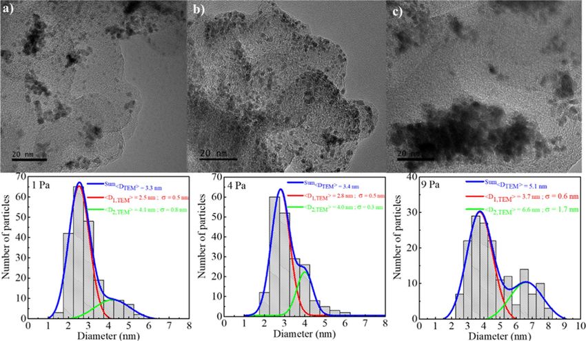
ylene glycol (PEG), it was reported that increasing the current formed NPs linearly increased with increasing the sputtering
from 10 to 50 mA leads to the formation of bigger NPs, from time. In this case, adjusting the sputtering time allows for
1.3 to 4.5 nm, respectively [127]. The authors explained it by getting the desired number of NPs in the host liquid [12]. For
the fact that usage of higher current allows for sputtering a example, long term (24 h) deposition of Cu onto 1-butyl-3-
higher number of atoms per time unit. Thus, the atoms will methylimidazolium bis(trifluoromethylsulfonyl)imide (BMIM-
collide with a higher frequency inside the liquid, hence forming TFSI) allowed the authors to produce 1 g of Cu NPs in 50 mL
larger NPs. Wender et al. reported that the size of NPs depends of IL [150].
on the current and the discharge voltage. According to them, the
NP size increases with increasing the current when sputtering At the same time, we cannot ignore several papers where
Au onto 1-butyl-3-methylimidazolium bis(trifluoromethylsul- authors mentioned the increase of the mean NP diameter
fonyl)imide (BMIM-TFSI) [129] and the population of small [126,127,138,139]. In the work by Sugioka et al. [126], Au was
Au NPs increases with increasing discharge voltage in case of sputtered on a very thin layer of HyEMI-BF4 and a quite signif-
1-butyronitril-methylimidazolium bis(trifluoromethyl- icant change of NP size was detected when increasing the depo-
sulfonyl)imide [(BCN)MIM-TFSI] [128]. At the same time it sition time: from 2.7 to 5.1 nm after 0.5 and 5 min, respectively.
was reported that an increase in discharge voltage leads to an In [127,138,139], PEG was chosen as a host liquid. A slight
increase in diameter of Ag and Au NPs produced by sputtering increase in the mean particle diameter was reported for Au sput-
onto castor oil [124,125]. An augmentation of the voltage tering (from 5.6 ± 1.8 nm after 5 min to 5.9 ± 0.8 nm after
applied at the cathode, at a given working pressure, will lead to 15 min) [138,139], and for Pt/Cu prepared via sputtering of an
an increase of the current, and therefore of the flux of atoms alloy target (from 1.2 ± 0.4 nm after 15 min to 3.1 ± 1.7 nm
reaching the liquid surface. after 4 h) [127]. It seems that the authors of these papers
[126,127,138,139] did not consider the fact that irradiation of
According to Hatakeyama et al. [114], an increase in the dis- the host liquid by the plasma species causes heating. For exam-
charge current (from 20 to 40 mA by varying the voltage) ple, some researchers used a very thin layer of host liquid
during the sputtering of gold onto 1-butyl-3-methylimida- (0.08 mL of IL was spread onto a 4 cm2 glass plate with 3.5 cm
zolium tetrafluoroborate (BMIM-BF4) mainly increases the of working distance [151] or 0.6 mL of IL was spread onto a
total concentration of metal and the number of Au NPs in the 10 cm2 glass plate [113,152,153]), which makes overheating
solution but hardly affects the NP size and their size distribu- very likely. This leads to a change in the viscosity and surface
tion. According to Qadir et al. [116], variations of the current do tension and might affect the diffusion of the sputtered species in
not affect the formation of palladium (Pd) NPs in 1-thioethyl- the liquid matrix which, in turn, changes the size of final NPs.
methylimidazolium bis(trifluoromethanesulfonyl)imide
[(HSE)MIM-TFSI]. Yonezawa’s group [120] showed that only 2.1.1.3 The working distance between target and liquid: Ac-
the absorbance of the Au NP solutions increases proportionally cording to Hatakeyama et al. [114], the working distance be-
with the current (from 10 to 30 mA) but not the size of the NPs tween the target and the host liquid surface does not affect the
after sputtering onto PEG. It was also shown that the size of size of NPs. The variation of this distance from 25 mm to
metal NPs does not depend on the sputter power in the case of 50 mm and finally to 75 mm, with all other parameters fixed,
sputtering iron (Fe) onto the surface of silicon oil [130] and in showed that the number of NPs increased with decreasing of the
the case of sputtering of Ag or Au onto castor oil [131,132]. distance, but the size of Au NPs and its distribution remained
the same.
We agree with Hatakeyama et al. [114] that researchers who
discuss about the influence of current and voltage on the NP As it was found during vacuum evaporation of silver onto
size never considered the fact that increasing the discharge cur- running silicon oil, changing the deposition rate by changing the
rent causes a heating of the host liquid surface and eventually distance between metal source and liquid might lead to heating
also a temperature increase of the target. As it can be evidenced of the liquid surface for the shortest distances, subsequently
in the next subsections an increase in liquid temperature changing the viscosity for long deposition processes and
changes its viscosity and might lead to the formation of larger impacting the size of the final NPs [154].
NPs.
2.1.1.4 The working gas composition: Ar was used as a
2.1.1.2 Sputter time: Influence of sputter time on the NP for- working gas in most of the papers with the exception of several
mation was studied in [12,113,117,118,120,122,125,126,129- works [12,120,142,143,147,155-157] that will be considered
149]. According to most of the researchers, the time of sput- below. The main reason for the wide usage of Ar for SoL, and
tering does not affect the size of NPs. However, the number of sputter deposition in general, is that it is a cheap and inert gas
22You can also read