Temporarily Alloying Titanium to Facilitate Friction Stir Welding - PNNL-18411
←
→
Page content transcription
If your browser does not render page correctly, please read the page content below
PNNL-18411

Prepared for the U.S. Department of Energy
under Contract DE-AC05-76RL01830

Temporarily Alloying Titanium to
Facilitate Friction Stir Welding

Y Hovanski

May 2009
DISCLAIMER

This report was prepared as an account of work sponsored by an agency of the
United States Government. Neither the United States Government nor any agency
thereof, nor Battelle Memorial Institute, nor any of their employees, makes any
warranty, express or implied, or assumes any legal liability or responsibility
for the accuracy, completeness, or usefulness of any information, apparatus,
product, or process disclosed, or represents that its use would not infringe
privately owned rights. Reference herein to any specific commercial product,
process, or service by trade name, trademark, manufacturer, or otherwise does not
necessarily constitute or imply its endorsement, recommendation, or favoring by
the United States Government or any agency thereof, or Battelle Memorial
Institute. The views and opinions of authors expressed herein do not necessarily
state or reflect those of the United States Government or any agency thereof.

            PACIFIC NORTHWEST NATIONAL LABORATORY
                               operated by
                               BATTELLE
                                  for the
              UNITED STATES DEPARTMENT OF ENERGY
                   under Contract DE-AC05-76RL01830

                        Printed in the United States of America

                    Available to DOE and DOE contractors from the
                     Office of Scientific and Technical Information,
                        P.O. Box 62, Oak Ridge, TN 37831-0062;
                                     ph: (865) 576-8401
                                    fax: (865) 576-5728
                              email: reports@adonis.osti.gov

        Available to the public from the National Technical Information Service,
       U.S. Department of Commerce, 5285 Port Royal Rd., Springfield, VA 22161
                                    ph: (800) 553-6847
                                    fax: (703) 605-6900
                             email: orders@ntis.fedworld.gov
                    online ordering: http://www.ntis.gov/ordering.htm

                        This document was printed on recycled paper.
                                          (9/2003)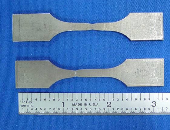
TEMPORARILY ALLOYING TITANIUM TO FACILITATE

             FRICTION STIR WELDING

                           By

                  YURI HOVANSKI

       A thesis submitted in partial fulfillment of
           the requirements for the degree of

MASTER OF SCIENCE IN MECHANICAL ENGINEERING

       WASHINGTON STATE UNIVERSITY
       Department of Mechanical Engineering

                       May 2009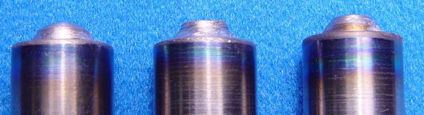
To the Faculty of Washington State University:

         The members of the Committee appointed to examine the thesis of
YURI HOVANSKI find it satisfactory and recommend that it be accepted.

                                        ___________________________________
                                             William C. Kinsel, Ph.D., Chair

                                        ___________________________________
                                             David P. Field, Ph.D.

                                        ___________________________________
                                             Hussein M. Zbib, Ph.D.

                                   ii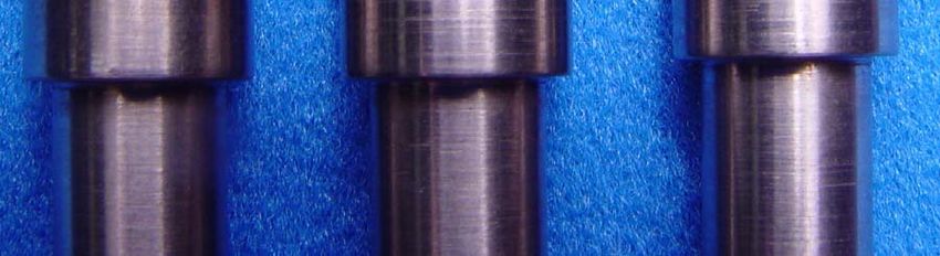
ACKNOWLEDGMENT

The author wishes to gratefully acknowledge the financial assistance of a Laboratory

Directed Research and Development project from Battelle – Pacific Northwest Division

as well as the continued financial support of Dr. Joseph Carpenter via the Automotive

Lightweight Materials program. All research herein was performed at the campus of the

Pacific Northwest National Laboratory. Gratitude is also expressed for the technical

support of Mr. Stan Pitman who assisted in the development of the thermohydrogen

processing parameters as well as for the expertise and advice of Mr. Curt A. Lavender

and Dr. K. Scott Weil who spent countless hours advising Mr. Hovanski in the intricacies

of titanium and titanium metallurgy.

                                           iii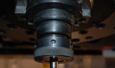
TEMPORARILY ALLOYING TITANIUM TO FACILITATE

                               FRICTION STIR WELDING

                                       ABSTRACT

                                by Yuri Hovanski, M.S.
                               Washington State University
                                       May 2009

Chair: William C. Kinsel

       While historically hydrogen has been considered an impurity in titanium, when

used as a temporary alloying agent it promotes beneficial changes to material properties

that increase the hot-workability of the metal. This technique known as thermohydrogen

processing was used to temporarily alloy hydrogen with commercially pure titanium

sheet as a means of facilitating the friction stir welding process. Specific alloying

parameters were developed to increase the overall hydrogen content of the titanium sheet

ranging from commercially pure to 30 atomic percent. Each sheet was evaluated to

determine the effect of the hydrogen content on process loads and tool deformation

during the plunge phase of the friction stir welding process. Two materials, H-13 tool

steel and pure tungsten, were used to fabricate friction stir welding tools that were

plunged into each of the thermohydrogen processed titanium sheets. Tool wear was

characterized and variations in machine loads were quantified for each tool material and

weld metal combination.

       Thermohydrogen processing was shown to beneficially lower plunge forces and

stabilize machine torques at specific hydrogen concentrations. The resulting effects of

hydrogen addition to titanium metal undergoing the friction stir welding process are

compared with modifications in titanium properties documented in modern literature.

                                             iv
Such comparative analysis is used to explain the variance in resulting process loads as a

function of the initial hydrogen concentration of the titanium.

                                             v
TABLE OF CONTENTS
Page
ACKNOWLEDGMENT.................................................................................................... iii
ABSTRACT....................................................................................................................... iv
LIST OF TABLES............................................................................................................ vii
LIST OF FIGURES ......................................................................................................... viii
NOMENCLATURE .......................................................................................................... ix
CHAPTER
1. INTRODUCTION ....................................................................................................... 1
Thermohydrogen Processing ...................................................................... 4
Friction Stir Welding Titanium Alloys ....................................................... 7
2. DESIGN PARAMETERS AND TEST CONFIGURATION ................................... 10
Controlled Alloying of Titanium Sheet with Hydrogen ........................... 10
Tool Design and Material Selection ......................................................... 12
Friction Stir Welding Plunge Testing ....................................................... 13
3. ANALYSIS AND DISCUSSION OF RESULTS..................................................... 18
Controlled Alloying of Titanium Sheet with Hydrogen ........................... 18
Tool Performance...................................................................................... 21
Friction Stir Welding Plunge Testing ....................................................... 23
Effect of Hydrogen on Flow Stress in Commercially Pure Titanium....... 27
4. CONCLUSIONS AND FUTURE RECOMMENDATIONS ................................... 33
Future Recommendations ......................................................................... 34
5. BIBLIOGRAPHY...................................................................................................... 35
6. APPENDIX................................................................................................................ 39
Appendix A: FSW Tool Drawing ............................................................ 39
Appendix B: Molar Breakdown of Hydrogen Content............................ 40
Appendix C: Reaction Forces and Torques Using an H-13 Tool ............ 41
Appendix D: Reaction Forces and Torques Using a Tungsten Tool ....... 44
viLIST OF TABLES
Table 1. Plunge test schedule........................................................................................... 16
Table 2. Specimen weight targets and actual weights used to determine hydrogen content
in thermohydrogen processed commercially pure titanium sheet..................................... 19
Table 3. Tabulated values of average peak loads and average peak torques recorded
during FSW plunge tests in thermohydrogen processed commercially pure titanium
sheets................................................................................................................................. 27
viiLIST OF FIGURES
Figure 1. Schematic illustration of FSW process............................................................... 1
Figure 2. Binary phase diagram for the titanium-hydrogen system at or below 1 MPa. ... 6
Figure 3. Detailed drawing of the friction stir welding tool pin used for plunge testing in
thermohydrogen processed titanium. ................................................................................ 12
Figure 4. High stiffness friction stir welding machine located at the Pacific Northwest
National Laboratory in Richland Washington. ................................................................. 13
Figure 5. Friction stir welding tool loaded into a #50 collet chuck tool holder............... 14
Figure 6. Schematic layout of plunge tests, showing the minimum 50 mm (2 inch)
spacing between plunge locations on the titanium sheet. ................................................. 17
Figure 7. Stress-Strain curve of dehydrided commercially pure titanium sheet. Yield
Stress of more than 400 MPa with a 48% area reduction. ................................................ 20
Figure 8. As-tested tensile specimens of dehydrided commercially pure titanium. ....... 21
Figure 9. Material buildup on tungsten tools after three FSW plunge tests in CP-Ti
alloyed with 10 (left), 20 (middle) and 30 (right) atomic percent hydrogen. ................... 22
Figure 10. Tool reaction loads showing the increased data scatter for hydrogen contents
above 10 atomic percent. .................................................................................................. 25
Figure 11. H-13 friction stir welding tool after three plunges in titanium sheet alloyed
with 20% atomic hydrogen. .............................................................................................. 26
Figure 12. Load and torque magnitudes for a FSW plunge test using a tungsten tool in
commercially pure titanium sheet..................................................................................... 29
Figure 13. Load and torque magnitudes for a FSW plunge test using a tungsten tool in
titanium sheet alloyed to 10% atomic hydrogen............................................................... 30
Figure 14. Load and torque magnitudes for a FSW plunge test using an H-13 tool in
commercially pure titanium sheet..................................................................................... 31
Figure 15. Load and torque magnitudes for a FSW plunge test using an H-13 tool in
titanium sheet alloyed to 5% atomic hydrogen................................................................. 32
viiiNOMENCLATURE
PNNL Pacific Northwest National Laboratory
WSU Washington State University
FSW Friction Stir Welding
CP-Ti Commercially Pure Titanium
THP Thermohydrogen Processing
DARPA Defense Advanced Research Projects Agency
hcp Hexagonal close pack
bcc Body-centered cubic
°C Degrees Celsius
At.% Atomic percent
Al Aluminum
V Vanadium
RPM Rotations per minute
mm Millimeters
sccm Standard cubic centimeters per minute
MPa Megapascals
α Alpha phase titanium
β Beta phase titanium
α+β Alpha-beta mixed phase
PCBN Poly-crystalline cubic boron nitride
ixDedication
This thesis is primarily dedicated to my loving wife Candice.
Her unwavering support and love helped me to stay on track and finish what I started.
I also dedicate this work to my father and other mentors and professors who diligently
worked to instill in me a love of mechanisms, science, materials and engineering.
Thank you.
xCHAPTER ONE
INTRODUCTION
Friction Stir Welding (FSW) is a relatively new solid state joining process that
has found wide spread acceptance throughout the welding and joining community since
its inception in 1991 by The Welding Institute [1]. The process employs a non-
consumable cylindrical tool that is rotated and plunged into the interface of two materials
and subsequently translated down that interface to form a linear weld. A schematic
illustration of the process in a butt weld configuration is shown in Figure 1. Distinctive
nomenclature associated with the process has been labeled within the Figure below,
showing the differences between advancing, retreating, leading and trailing locations in
the weld.
Figure 1. Schematic illustration of FSW process.
1Applications for FSW in light weight materials such as aluminum became
immediately apparent as the rapid implementation of low-cost, emission free FSW
quickly overcame the historical difficulties of welding aluminum alloys [2-4].
Implementation of FSW in higher strength materials such as steel and titanium is proving
more problematic, for traditional fusion welding and solid state joining techniques such
as diffusion bonding are already industrially acceptable for these high strength materials.
Thus, the justification for implementing FSW in such material systems was developed
more as a means of enhancing the processability and properties of joints than as a
competing joining technology. Such is the case with FSW titanium structures, where
specific processing parameters can be developed to provide refined grain structures
within the welded region closely resembling the parent material. Such Microstructural
modification allows for retention of crucial properties such as uniform formability,
corrosion resistance, and other mechanical properties that originally led to the selection
of a titanium alloy.
FSW of titanium alloys has recently received a great deal of attention leading to a
sizable Defense Advanced Research Projects Agency (DARPA) program to enable the
process as part of a larger more comprehensive titanium initiative [5]. This program and
other more independent research investigations have shown marked progress in the
successful joining of titanium alloys via FSW [6-10]. However, while significant
research and development has specifically focused on the selection of appropriate tool
materials for FSW titanium alloys, industrial deployment of this technology is still
hampered by an inability to provide high-cycle, reusable tooling that is readily accessible
and cost efficient [6-7, and 11].
2Tool failures in titanium alloys are primarily related to excessive wear and
deformation that occur during the initial plunge phase of the FSW process, in which the
rotating tool is thrust into the weld material [6-8]. Deformation of the tool pin, the
reduced diameter section of the tool beneath the larger tool shoulder, generally yields a
reduction in the pin length that result in insufficient weld depth to consolidate the lower
regions of the weld joint. This problem is further exacerbated by the chemical reactivity
of titanium with many carbon based superabrasives that prevents the use of typical
materials used for friction stir welding high strength materials.
Investigations up to this point have focused on finding the proper tool material to
survive the heat, friction, reaction forces and chemical reactivity inherent in FSW
titanium alloys; however, little has been done to investigate the potential of temporarily
modifying the material to facilitate the FSW process. Historically the interaction of
hydrogen and titanium has been strictly avoided in production and processing of titanium
alloys, yet increased understanding of the unique alloying properties of hydrogen in
titanium are being further explored. Modern research shows that hydrogen utilized as a
temporary alloying element in titanium alloys provides enhancements in areas such as hot
workability, machining, sintering and compaction while simultaneously providing for
controlled modification of specific mechanical properties including ultimate and yield
stress, bulk and shear modulus, and elongation [12-18]. The data amassed relating the
beneficial nature of such temporary alloying, known as Thermohydrogen Processing, has
yet to find wide spread utilization due to numerous factors including the strict aerospace
regulations prohibiting hydrogen contamination in titanium alloys. Nevertheless, distinct
3areas show that small scale deployment of thermohydrogen processing is enabling
processing and production of titanium that were previously untouched [19-27].
Commercially pure titanium sheet was temporarily alloyed with hydrogen to
facilitate FSW by selectively modifying the material properties to reduce process loads
and deter chemical reactivity. Thermohydrogen processing conditions were developed to
alloy titanium with hydrogen at varied mixture ratios ranging from commercially pure to
thirty atomic percent hydrogen.
As tool failure in titanium FSW is generally related to deformation of the pin
during the plunge phase, extensive linear testing was determined to be out of the scope of
this study. As such, numerous plunge tests were conducted on each of the
thermohydrogen processed titanium sheets. Loads and torques were monitored and
recorded during these plunge experiments, and were systematically compared to evaluate
the influence of varied hydrogen concentrations on process loads during the plunge phase
of the FSW process. Tool wear and reactivity were also characterized in order to
determine the effective lifecycle of each tool material combination.
Thermohydrogen Processing
The use of hydrogen as a temporary alloying element to improve the processing,
microstructure, and mechanical properties of titanium alloys has become known as
thermohydrogen processing [20-21, 23, and 25-26]. This process entails adding
hydrogen to a titanium alloy by exposing the material to a hydrogen environment at an
increased temperature, performing a subsequent heat treatment or thermomechanical
processing, and finally removing the hydrogen via a vacuum anneal. The practice of
4modifying the properties of titanium metals with hydrogen alloying is based on the
influence of hydrogen on the kinetics of phase transformations, the overall phase
compositions, and the ability to form novel metastable phases. Such metallurgical
changes provide a number of advantages when processing titanium alloys including
increased hot workability of the α, pseudo-α and α + β phases [20-21, and 24-27].
Examination of the binary phase diagram for the titanium-hydrogen system,
Figure 2, shows that an addition of a small percentage of hydrogen quickly destabilizes
the low temperature hcp α-phase allowing some portion of the α-phase to be transformed
into the bcc β-phase. Consequently an addition of hydrogen also stabilizes the higher
temperature bcc β-phase by lowering the temperature of the α to β phase transformation.
Furthermore, an initial increase in hydrogen further promotes the two-phase (α + β)
region above approximately 7 % atomic at the eutectoid temperature. These
fundamental differences in the phase kinetics of titanium metal lead to changes in the rate
and temperature of martensite transformations, with increasing hydrogen concentrations
yielding reductions in both the temperature of formation and rate of cooling required to
induce such transformations. Such basic alterations in the structure and phase kinetics of
the material are consequential due to the significant reduction or inflation of material
properties specific to each phase in the titanium-hydrogen system. An example of the
effect of such distinct changes in the material properties from phase to phase is the rapid
decrease in the shear and Young’s moduli of the α phase with increasing hydrogen
content. In contrast, a similar increase in the hydrogen content of the β-phase leads to an
increase in both moduli [12-13].
5Liquid
βTi
αTi αTi+ β
δTi
αTi +δ
αTi + γ
Figure 2. Binary phase diagram for the titanium-hydrogen system at or below 1 MPa.
Figure 2 demonstrates that an addition of roughly 39 at.% hydrogen reduces the α
to β phase transformation temperature from 882°C to 300°C. This nearly linear
relationship shows that an increase of one atomic percent hydrogen yields a reduction of
approximately 13.7°C in the beta transus temperature. As the β phase shows no stability
below the eutectoid temperature, a combination of α + δ phase are formed for hydrogen
concentrations above 6.8% atomic and below 300°C followed by a transformation to an α
+ γ phase below 168°C. These subsequent cooling transformations lead to volumetric
6expansion that develop considerable internal stresses often manifesting themselves in
visible distortion of the hydrogen alloyed metal as reported by others [40-42]
Thermohydrogen processing of titanium alloys is often used to stabilize the β
phase by adding sufficient hydrogen to prevent phase changes during processing. Such
phase stabilization during processing can prevent catastrophic failures during forming
and joining that are created from the significant and rapid changes in material properties
that take place at the transition between the α and β phases. Thus, stabilization of either
phase simply allows for more uniform performance without sudden shifts in reaction
loads from the titanium metal. As many hot working processes take place at or near the
β-transus of commercially pure titanium, thermohydrogen processing provides a means
of stabilizing the β phase by effectively lowering the transition temperature below the
effective operation condition. Many of the variations of thermohydrogen processing
techniques were previously summarized [20-21, and 25-26].
Friction Stir Welding Titanium Alloys
The commencement of FSW in aluminum alloys in the early nineties stemmed a
flurry of activity applying this technology to other material systems. FSW provides many
advantages joining aluminum alloys when compared to traditional fusion welding
including elimination of toxic cover gases, reduced power consumption, increased
repeatability and safety as well as numerous positive benefits in the post-weld
microstructure that enhance the final mechanical properties. To date, FSW has been
commercially developed for numerous aluminum alloys, and has been demonstrated in
copper, magnesium, zinc, mild and advanced high strength steel alloys, stainless steels,
7polymers, cast iron, titanium alloys and dissimilar combinations of the same [33]. While
FSW of aluminum and other low melting, structural alloys has rapidly matured and found
widespread industrial utilization, further development is required for higher temperature
materials like titanium and steels.
Attempts at FSW titanium alloys were first reported in the late nineteen nineties,
and have since been made in numerous titanium alloys over the past decade, including
commercially pure titanium, titanium 6Al-4V and other alpha-beta alloys, near alpha
alloys, and beta alloys [6, 8, and 10]. Results varied from complete tool failure to the
production of commercially viable joints with remarkable post-weld properties
While commercial success in aluminum alloys is unfettered, numerous advances
are yet required to enable wide spread applicability of friction stir joining in higher
strength material systems. One such advancement was the application of polycrystalline
cubic boron nitride (PCBN) and other super abrasive resistant materials in FSW tool
manufacturing that have greatly enabled this joining process in steels. Unfortunately,
these same tool materials cannot be used in titanium alloys due to the increased affinity
of titanium to react with key elements within PCBN. Attempts to use tooling
manufactured from PCBN and super abrasive materials have often proven disastrous on
the first plunge, with costly tooling being effectively eroded and chemically etched away
in seconds.
Significant improvements have nevertheless been made in FSW titanium alloys,
yet nearly all progress indicates that further evolution in tool design and materials remain
the largest issue in the overall process development. Certain tungsten based materials
have proven most successful, although tool wear was previously reported [6-7], and tool
8deformation during the plunge phase was specifically characterized [6]. Deformation of
the tool pin during the plunge phase, known as “mushrooming”, results from a
combination of high reaction loads and low temperatures of the weld material during the
initial tool plunge. This brief destructive period in the overall process has been
somewhat mitigated as a result of state-of-the-art FSW machines that allow for variation
in rotational velocities during the plunge and traverse portions of the FSW process.
Results from such variation in rotational speeds were reported by Jones and Loftus [6]
showing that tool deformation in a lanthanated tungsten alloy could be reduced by 50%
by increasing the rotational speed during the plunge phase from 500 RPM to 900 RPM.
However, even with such process modifications tool deformation during plunging
remained a constant barrier preventing otherwise reusable tooling.
9CHAPTER TWO
DESIGN PARAMETERS AND TEST CONFIGURATION
The objective of this study was to evaluate the effect of adding various hydrogen
concentrations to commercially pure titanium on the reaction loads during the plunge
phase of the FSW process. This overall objective was broken into two tasks. The first
was developing a controlled alloying process for large titanium sheets, and the second
was evaluating the effect of such thermohydrogen processing on the reaction loads during
the plunge phase of FSW.
Controlled Alloying of Titanium Sheet with Hydrogen
Rectangular sheet specimens 137 mm in width and 406 mm in length were
prepared by shearing a larger 2.54 mm thick commercially pure titanium sheet into five
sections. The individual sections were subsequently alloyed with hydrogen to achieve
concentrations ranging between commercially pure and 30 atomic percent hydrogen.
Each sheet was individually wrapped in titanium foil as a means of gettering impurities
during the alloying process. These impurities, inherent to the high purity hydrogen gas
that was used as the hydrogen source during the alloying process and those present from
reactions within the vacuum furnace, could otherwise inhibit the hydriding process.
Specimens were placed in a vacuum furnace that was evacuated to a level of
approximately 10-5 torr and heated to 800°C. After heating, high purity hydrogen gas
was introduced to the vacuum chamber and specimen using a mass flow controller at a
10rate of 200 sccm. The foil wrapped sheets were held at temperature to allow for the
favorable reaction kinetics at 800°C [28-32 and 34-39] to more rapidly diffuse the
hydrogen throughout the intended titanium specimen. Once the reaction was sufficiently
underway, as characterized by a drop in pressure of the chamber after the introduction of
the target mass of hydrogen, the temperature was lowered and held at 350°C until the
balance of the reaction was complete.
The hydrogen content of each sheet was varied by controlling the mass of the
hydrogen gas introduced into the vacuum chamber. The target hydrogen levels chosen
for this study were commercially pure, 5, 10, 20, and 30 atomic percent. Verification of
hydrogen accumulation was comparatively evaluated by measuring the difference
between the initial and final mass of each specimen; each sheet was measured to the
nearest 0.01 grams. Specimens were again weighed after alloying in both the wrapped
and unwrapped conditions to verify the hydrogen content of both the wrapped composite
and individual specimens.
Mechanical properties of the baseline titanium were initially verified via a
mechanical testing and found to be essentially identical to material that had undergone
thermohydrogen processing followed by subsequent vacuum annealing process to remove
the hydrogen. Properties of yield strength, ultimate strength and elongation of titanium
samples before and after thermohydrogen processing demonstrated little measurable
deviation in samples tested in this study.
11Tool Design and Material Selection
FSW tools were designed for testing thermohydrogen processed titanium sheet.
Tool materials consisted of pure tungsten and H-13 hot-worked steel. Each tool was
fabricated with a 1.65 mm pin length and a maximum shoulder diameter of 12.7 mm. A
design drawing for the tools used in this study is presented in Appendix A, while a
detailed blowup of the tool pin is shown in Figure 3. The tool was intended to provide
approximately a 2:3 aspect ratio of pin to shoulder diameter at the location where the pin
connects to the tool shoulder. From this location the pin diameter reduced linearly over
the 1.65 mm length to a final diameter of 6.3 mm for a 1:2 aspect ratio of pin to shoulder
diameter. While this tool pin is considerably wider than more traditional FSW pin tools,
recent research in FSW of titanium has demonstrated their effectiveness [6-7, and 11].
H-13 tools were heat treated to H-925 after machining, and each were tested and
found to have attained a hardness of 40 Rockwell C. Tungsten material utilized for tool
fabrication was recrystallized rod that ranged between 37 and 39 Rockwell C at room
temperature. All tungsten tools were used in their as-machined state with no coatings or
heat treatment employed.
Figure 3. Detailed drawing of the friction stir welding tool pin used for plunge testing in
thermohydrogen processed titanium.
12Friction Stir Welding Plunge Testing
Plunge tests were designed to provide comparisons between the tool loads
generated during the plunge phase of the FSW process. For plunge testing, tools were
rotated and plunged (z-axis movement) into the titanium sheet, without any x-axis or y-
axis translation. Initial tests were used to evaluate the effect of varying levels of
hydrogen in otherwise commercially pure titanium sheet on the plunge force and torque.
As a means of further characterizing the influence of hydrogen on FSW of titanium, two
distinctly different tool materials were used, and each tool was plunged with identical
parameters a total of three times. Tools were removed from the tool holder following
each plunge, examined visually, and allowed to cool prior to further testing. A minimum
spacing between plunge tests was established at roughly 50 mm to avoid any overlapping
of the heat affected areas of each test case.
Figure 4. High stiffness friction stir welding machine located at the Pacific Northwest
National Laboratory in Richland Washington.
13All testing was performed on a Transformation Technologies Inc. friction stir
welding machine located at the Pacific Northwest National Laboratory shown in Figure
4. Each sheet was clamped onto a flat, steel anvil prior to testing regardless of the
distortion resulting from the alloying process. Tools were fixed into a #50 tapered collet
chuck using a 9.525 mm (3/8 inch) diameter collet, allowing for tools to be shoulder
loaded onto the collet face as shown in Figure 5. Neither the tools nor the tool holder
were cooled during testing. To minimize oxidation of the titanium surface and tool
materials an argon cover gas was constantly applied to the tool from a time prior to tool
insertion until the tool had been removed for several seconds. Argon gas was applied
using a copper tubing gas diffuser that liberally applied argon at a rate 14,000 sccm
throughout the testing process.
Plunge Direction
#T-50 Collet Chuck
3/8” Collet
Tool Shoulder
Tool Pin
Figure 5. Friction stir welding tool loaded into a #50 collet chuck tool holder.
14The data acquisitions systems on the aforementioned FSW machine provided
continuous feedback of all parameters required to monitor position and load. The
machine axes with respect to the tool are such that the Z-Axis aligns with the plunge
direction of the tool as shown in Figure 5, the X-Axis aligns with the travel direction of a
weld, and the Y-Axis is the lateral direction to the weld.
Forces and positions are monitored for each axis providing a continuous record of
the commanded position or force as well as the actual or achieved value. Data acquired
during plunge testing included all tool loads, machine torques, plunge depths, and
machine velocities. Forces were measured by a combination of three load cells located at
a fixed diameter off the z-axis (plunge axis) and separated at 120 degree intervals. Z-
loads were computed as a direct summation of the resulting three magnitudes, while x-
axis and y-axis forces are computed based on the moment-force relationship specific to
the tool setup. Torque measurements are derived from the load variations from cell to
cell, but were also directly computed from the motor drive output on the spindle motor.
All position data was directly read from the motor encoders on the ball screw driven
drive train.
15Table 1. Plunge test schedule.
Tool Identification Plunge Parameters
Plate Test # Plunge At % Tool Tool Plunge Plunge Plunge
ID ID# H ID # Material # Rate RPM
1 CP-1 0 H13-1 H13 1 5mm/min 400
CP-Ti Sheet
2 CP-2 0 H13-1 H13 2 5mm/min 400
3 CP-3 0 H13-1 H13 3 5mm/min 400
7 CP-7 0 W-1 W 1 5mm/min 400
8 CP-8 0 W-1 W 2 5mm/min 400
9 CP-9 0 W-1 W 3 5mm/min 400
13 H20-1 20 H13-2 H13 1 5mm/min 400
14 H20-2 20 H13-2 H13 2 5mm/min 400
Plate #2
15 H20-3 20 H13-2 H13 3 5mm/min 400
19 H20-7 20 W-2 W 1 5mm/min 400
20 H20-8 20 W-2 W 2 5mm/min 400
21 H20-9 20 W-2 W 3 5mm/min 400
25 H10-1 10 H13-3 H13 1 5mm/min 400
26 H10-2 10 H13-3 H13 2 5mm/min 400
Plate #1
27 H10-3 10 H13-3 H13 3 5mm/min 400
31 H10-7 10 W-3 W 1 5mm/min 400
32 H10-8 10 W-3 W 2 5mm/min 400
33 H10-9 10 W-3 W 3 5mm/min 400
37 H5-1 5 H13-4 H13 1 5mm/min 400
38 H5-2 5 H13-4 H13 2 5mm/min 400
Plate #3
39 H5-3 5 H13-4 H13 3 5mm/min 400
43 H5-7 5 W-4 W 1 5mm/min 400
44 H5-8 5 W-4 W 2 5mm/min 400
45 H5-9 5 W-4 W 3 5mm/min 400
49 H30-1 30 H13-5 H13 1 5mm/min 400
50 H30-2 30 H13-5 H13 2 5mm/min 400
Plate #4
51 H30-3 30 H13-5 H13 3 5mm/min 400
55 H30-7 30 W-5 W 1 5mm/min 400
56 H30-8 30 W-5 W 2 5mm/min 400
57 H30-9 30 W-5 W 3 5mm/min 400
Plunge tests were executed per the test plan in Table 1 and the schematic shown
in Figure 6. A total of five sheets were evaluated, four that had undergone various levels
of thermohydrogen processing and one baseline commercially pure variant. A minimum
16of six plunges were made in each sheet; thus, allowing both the H-13 and tungsten tool
materials to be tested at least three times in each material condition.
Figure 6. Schematic layout of plunge tests, showing the minimum 50 mm (2 inch)
spacing between plunge locations on the titanium sheet.
17CHAPTER THREE
ANALYSIS AND DISCUSSION OF RESULTS
Controlled Alloying of Titanium Sheet with Hydrogen
As each of the titanium sheets was wrapped in titanium foil prior to undergoing
the hydrogen alloying process, some question as to the uniformity of the hydrogen
distribution in the final wrapped sheets existed. Nevertheless, in all cases the hydrogen
gas was found to react uniformly with both the outer foil and inner sheet. This was
verified by examining both the individual and composite mass increases of the titanium
sheet and titanium foil wrappings. The actual measured weights and hydrogen contents
of the unwrapped titanium sheets are presented in Table 2, in which the alloyed masses
are presented based on an empirical balance from elemental analysis. A complete molar
breakdown is presented in detail in Appendix B.
Having wrapped each sheet with foil to getter impurities present in the hydrogen
gas supply and furnace atmosphere, the overall foil integrity was crucial to prevent
increased surface oxidation during the alloying process. The integrity of the wrapped foil
was shown to be adequate in all trials except the 30% atomic case in which the distortion
of both the plate and foil during the alloying process led to severe cracking and fracture
of the outer foil. This was attributed to the macroscopic distortion related to lattice
changes during cooling in which the bcc β phase transforms to the α + β and subsequent α
+ δ phases as was discussed in previous studies [40-42]. Nevertheless, even with the
18failed integrity of the titanium foil in this case, the overall sheet and foil demonstrated
uniform absorption of hydrogen as determined from the individual mass increases.
Table 2. Specimen weight targets and actual weights used to determine hydrogen content
in thermohydrogen processed commercially pure titanium sheet.
Target Initial Mass Final Mass Actual
(% atomic) (grams) (grams) (% atomic)
5 693.43 694.27 5.44
10 694.37 695.95 9.75
20 691.64 695.5 20.96
30 684.1 689.49 27.24
Wrapped specimens were initially taken to 800°C during the alloying process in
order accelerate the rate of absorption and diffusion of hydrogen in the titanium. This
temperature range was used to better utilize the more favorable kinetics of hydrogen
absorption and diffusivity at higher temperatures. While the overall solubility of
hydrogen is lower at 800°C than at temperatures below 500°C, the beneficial increases in
diffusivity and surface reactivity were found to promote the initial alloying process.
Once this reaction was initiated, the temperature was reduced to take advantage of the
increased solubility at lower temperatures. At a temperature of 350°C all remaining
hydrogen was found to react with the titanium. This reaction was determined to be
complete when the pressure increase related to the addition of a fixed mass of hydrogen
in the vacuum chamber was eliminated due to the reaction of the gas into the titanium
solid.
As one of the most commonly voiced concerns related to temporary alloying of
titanium with hydrogen involves the restoration of the original material properties of the
titanium metal after removal of the hydrogen, several tests were performed to
19demonstrate the post vacuum annealed properties of commercially pure titanium sheet.
Stress-strain curves of two distinct sheets used in this project were made using specimens
that had undergone a low temperature vacuum anneal having previously been alloyed
with hydrogen. This data shown in Figure 7 along with the accompanying picture of the
as tested specimens in Figure 8 seem to demonstrate that baseline ductility and strength
have been restored. In view of the fact that such results are well documented in the
literature for numerous alloys and hydrogen reduction techniques, no additional testing
was performed to verify that pre-alloyed properties could be restored.
800
700
600
500
Stress (MPa)
400
300 СP-1
CP-2
200
100
0
0 0.1 0.2 0.3 0.4 0.5 0.6 0.7
Strain (%) based on 12.7 mm Initial Length
Figure 7. Stress-Strain curve of dehydrided commercially pure titanium sheet. Yield
Stress of more than 400 MPa with a 48% area reduction.
20Figure 8. As-tested tensile specimens of dehydrided commercially pure titanium.
Tool Performance
As plunge parameters were held constant for all testing, variability in the resulting
data is related to the differing hydrogen content of the sheet as well as the differences in
tool materials. A new tool was used with each sheet, and a total of three plunges were
made with each tool material in all five titanium sheets. Performance of the tungsten and
steel tools deviated greatly based on the overall hydrogen content of the base metal.
Tungsten tools demonstrated the best performance in commercially pure titanium
that had been alloyed to a level of 10% atomic hydrogen. With this relatively small
addition of hydrogen absorbed into the base material, no measurable deformation of the
pin was detected. As previously cited, tungsten based tools used in commercial titanium
and its alloys generally lead to deformation of the pin during the plunge phase. Such was
21also witnessed herein, as plunging of tungsten tools in commercially pure titanium
deformed the pin, effectively “mushrooming” or reducing the overall pin length. After a
total of three plunges the pin length had effectively been reduced by approximately 17%
from 1.651 to 1.361 mm.
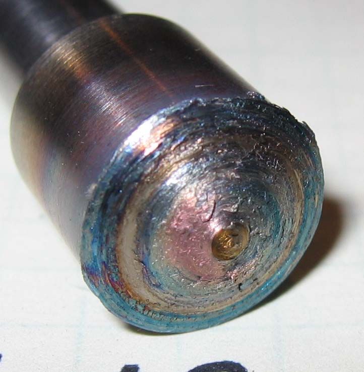
Each of the three tungsten tools used for experiments in the titanium sheet
containing 10, 20 and 30 atomic percent hydrogen demonstrated comparable
performance, with the hydrogen alloyed titanium building up on the ends of the pins as
shown in Figure 9. While this was problematic for repetitive plunging, simple translation
was shown to remove such buildup in all cases. While no concentrated effort to develop
traverse feed rates was made, some translation with tungsten tools demonstrated that
buildup from repetitive plunging was quickly removed at the initiation of lateral
movement.
Figure 9. Material buildup on tungsten tools after three FSW plunge tests in CP-Ti
alloyed with 10 (left), 20 (middle) and 30 (right) atomic percent hydrogen.
22Generally speaking tungsten materials performed better than the steel showing
less oxidation, deformation, chemical sensitivity and wear. The H-13 steel tool used with
commercially pure titanium was deformed at the shoulder and pin effectively
“mushrooming” any surface that came in contact with the titanium sheet. Hydrogen
contents of both 20% and 30% atomic, led to significant wear and chemical reactivity
between the steel tool and the basemetal. Steel tools demonstrated the best performance
in titanium alloyed with hydrogen at a level of 5% and 10% atomic. In both of these
conditions, the H-13 tools showed little to no measureable deformation. More significant
chemical reactivity was noticed in the 10 % atomic loading condition, as the tool material
showed oxidation and material buildup on the surface of the pin and shoulder. The steel
tool utilized for testing the titanium alloyed with 5% atomic hydrogen revealed no
distinguishable wear after three plunges. While the surface of this tool displayed visible
oxidation, it was not damaged by deformation and wear that hampered this tool material
in all other test cases.
Friction Stir Welding Plunge Testing
Just as the actual tool performance deviated greatly with variation in hydrogen
content and material, the resulting loads were also distinctively unique. Both hydrogen
content and tool material greatly influenced the stability and magnitude of the reactive
forces and torques. Appendices C and D contain a complete set of graphs plotting the
reactive forces and torques for each test case evaluated in this study.
As three individual plunge tests were performed in each titanium sheet, variation
from plunge to plunge was quite probable especially due to the extent of wear detected in
23the tools used for several of the test conditions. While deviation based on tool
deformation and wear from test to test seemed highly plausible, in actuality very little
variation was observed. Figure 10 shows z-axis load data for the three plunge set that
demonstrated the greatest divergence in all the recorded plunge forces. Such deviation
was noticed for this case in which the tool shape was significantly worn and deformed by
successive plunging of an H-13 tool in titanium alloyed with 20% atomic hydrogen as
shown in Figure 11.
While individually the point by point differences in magnitude are significant as
demonstrated by the real-time force plots shown in Figure 10 (a), the overall maximum
loads and force trend lines actually show very little variation in peak magnitudes. Figure
10 (b) shows plots of the trend lines for the force data presented in Figure 10 (a). With
the initial maximum loads of each trend line showing nearly identical peaks, the test by
test deviation may be explained by the deformation of the tool that increased with each
subsequent test. For the set of data shown in Figure 10, test 13 was run first followed in
numerical order by test 14 and 15. The magnitude of the load from test to test during the
7 to 15 second time range increased with each test, which may also be related to the
additional buildup of material on the tool pin and shoulder as well as the overall
deformation of the tool. Such assumptions also help to explain the divergence in load
magnitudes during the last five seconds, which seem to be adversely affected by the
increasing length of the pin resulting from material buildup.
Comparative measurements of all other load data sets demonstrated less variation
than that shown in Figure 10, and as such all additional data is presented individually
without further comment on test specific divergence.
24A) 10000
9000
Test 13
8000 Test 14
Test 15
7000
Z-Axis Loads (N)
6000
5000
4000
3000
2000
1000
0
0 5 10 15 20 25 30
Time (sec)
B) 10000
Test 13
9000
Test 14
Test 15
8000
10 per. Mov. Avg. (Test 15)
10 per. Mov. Avg. (Test 13)
7000
10 per. Mov. Avg. (Test 14)
Z-Axis Loads (N)
6000
5000
4000
3000
2000
1000
0
0 5 10 15 20 25 30
Time (sec)
Figure 10. Tool reaction loads showing the increased data scatter for hydrogen contents
above 10 atomic percent.
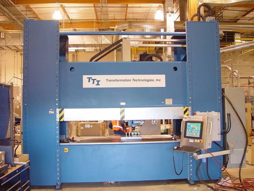
25Figure 11. H-13 friction stir welding tool after three plunges in titanium sheet alloyed
with 20% atomic hydrogen.
Average peak magnitudes for tool reaction forces and torques along with the
standard deviation of the set are presented in Table 3. An additional column in Table 3
presents comparative data showing the average percent reduction in the peak magnitude
of the plunge force in thermal hydrogen processed titanium from the commercially pure
equivalent. As the intent of temporarily adding hydrogen to the titanium sheet was to
facilitate the friction stir process, reducing the overall plunge loads to avoid tool
deformation and wear was desirable.
26Table 3. Tabulated values of average peak loads and average peak torques recorded
during FSW plunge tests in thermohydrogen processed commercially pure titanium
sheets.
Plate ID Max Standard Max Z- Standard Force
Torque Deviation Force Deviation Reduction
(N-m) (N-m) (kN) (kN) (%)
Tungsten Tooling
Cp-Ti 23.3 0.8 16.2 0.11 NA
Plate #1 (10% H) 26.4 2.74 11.86 0.46 26.8
Plate #2 (20% H) 20.7 0.32 11.34 1.2 30
Plate #3 (5% H) 24.3 0.68 12.35 0.89 23.8
Plate #4 (30% H) 24.1 3.06 11.32 0.57 30.1
H-13 Tooling
Cp-Ti 19.08 0.35 11.04 0.4 NA
Plate #1 (10% H) 16.97 5.12 8.53 0.8 22.8
Plate #2 (20% H) 17.64 4.62 8.55 0.83 22.6
Plate #3 (5% H) 20.03 1.7 9.42 0.34 14.7
Plate #4 (30% H) 17.8 1.8 7.83 0.89 29.1
Effect of Hydrogen on Flow Stress in Commercially Pure Titanium
As there are numerous methodologies that may be employed to reduce the
applicable flow stresses relevant to a discussion on friction stir welding titanium, a more
detailed look at the influence of hydrogen and temperature on the phase kinetics and flow
stresses applicable to the friction stir regime seems appropriate.
The hcp α-phase transition to bcc β phase at 882°C in commercially pure titanium
produces a sizable reduction in both the yield and flow stresses of commercially pure
titanium alloys. Senkov and others [12, 21] demonstrated the yield stress of an α-phase
commercially pure titanium at 800°C exceeded 40 MPa, yet an increase over the β
transition temperature to 900°C reduced the yield stress to less than 15 MPa. A similar
27reduction in yield stress was demonstrated without increasing the temperature, but instead
increasing the hydrogen content adequately to drop the β transition temperature below the
800°C threshold. For the case in point a hydrogen content of 9% atomic resulted in a
reduction of the yield stress at 800°C to a level comparable with commercially pure
titanium at 900°C [12, 21]. The influence of increasing temperature and hydrogen
content had an even more dramatic effect on the reduction of flow stresses in titanium. A
9% atomic increase in hydrogen reduced the flow stress at 800°C from 110 MPa to below
50 MPa, while an increase in temperature from 800°C to 900°C exhibited a similar effect
[12].
Significant reductions in both yield stress and flow stress can be realized with
increasing hydrogen content of both the α and α + β phases. Conversely, an increase in
the hydrogen content of β phase titanium produces a deleterious effect on overall stress
reduction [12, 18-21]. Senkov [12] showed that any increase in hydrogen content of β
phase titanium yielded an increase in the yield stress and flow stress at temperatures
ranging from 500°C to 920°C. Furthermore, he demonstrated that the effective escalation
in flow stress with increasing hydrogen was exacerbated at increasing strain rates, having
evaluated strain rates from 0.001/second to 1.0/second. This rise in the flow stress
related to increasing hydrogen concentration was tempered for hydrogen concentrations
below 10% atomic, but exponentially increased as hydrogen concentrations were
increased to 30% atomic and beyond [12].
Previous experiments in FSW titanium alloys show that peak weld temperatures
vary between 700°C and 1000°C, which indicates that the greatest reductions in flow
stress may be achieved at hydrogen contents ranging between 9% atomic and 15% atomic
28based on the results previously discussed from others [12, 18-21]. Senkov and others
also demonstrated that at 700°C and 15% atomic hydrogen, commercially pure titanium
is β-phase stabilized with a flow stress minimum of below 70 MPa for strain rates of 1.0
s-1. They also showed that increasing the temperature to 800°C or 900°C only reduces
the effective flow stress by 20 MPa per 100°C interval, yet a reduction to 600°C
increases the same by more than 50 MPa and transitions back to the α + β phase. Thus,
increasing the hydrogen content of the basemetal sufficiently to stabilize the β-phase for
the applicable thermal regime would lead to increased stability while reducing the z-axis
reaction loads.
18000 30
Z-Axis Force
16000
Spindle Torque
25
14000
Spindle Torque (N-m)
12000 20
Z-Force (N)
10000
15
8000
6000 10
4000
5
2000
0 0
0 5 10 15 20 25 30
Time (sec)
Figure 12. Load and torque magnitudes for a FSW plunge test using a tungsten tool in
commercially pure titanium sheet.
29Plots of tool loads and torques are presented in Figures 12 thru 15, demonstrating
the effect of thermohydrogen processing on tool loads during the plunge phase of friction
stir welding. While peak values were previously reported in Table 3, the transient nature
of the plunge phase influences the overall process loads and torques throughout the 25
second duration. Tool reaction loads are generally highest during the initial portion of
the plunge, and this is also the segment that has the lowest temperatures. As the tool
continues to plunge into the basemetal, friction and pressure begin to heat the sheet,
effectively plasticizing a portion of the material around the tool. The increased
temperature of this stirred region directly benefits from the resulting stress reductions
association with the addition of hydrogen.
14000 30
Z-Axis Force
12000 Spindle Torque
25
10000
Spindle Torque (N-m)
20
Z-Force (N)
8000
15
6000
10
4000
5
2000
0 0
0 5 10 15 20 25 30
Time (sec)
Figure 13. Load and torque magnitudes for a FSW plunge test using a tungsten tool in
titanium sheet alloyed to 10% atomic hydrogen.
30Increased hydrogen content yields reductions in the average tool reaction forces at
the end of the plunge; however, the overall uniformity of the load magnitude or stability
of the reaction to the tool plunge seems to diminish for hydrogen contents above 10%
atomic. This may be related to the overall increased embrittlement of the titanium for
increasing contents of hydrogen. Such changes in the ductility of the material may be
leading to more incremental brittle failure mechanisms that tend to generate less uniform
load profiles.
12000 30
Z-Axis Force
Spindle Torque
10000 25
Spindle Torque (N-m)
8000 20
Z-Force (N)
6000 15
4000 10
2000 5
0 0
0 5 10 15 20 25 30
Time (sec)
Figure 14. Load and torque magnitudes for a FSW plunge test using an H-13 tool in
commercially pure titanium sheet.
3110000 30
9000 Z-Axis Force
Spindle Torque
25
8000
7000
Spindle Torque (N-m)
20
6000
Z-Force (N)
5000 15
4000
10
3000
2000
5
1000
0 0
0 5 10 15 20 25 30
Time (sec)
Figure 15. Load and torque magnitudes for a FSW plunge test using an H-13 tool in
titanium sheet alloyed to 5% atomic hydrogen.
32CHAPTER FOUR
CONCLUSIONS AND FUTURE RECOMMENDATIONS
While historically hydrogen has been considered an impurity in titanium, when
used as a temporary alloying agent it promotes beneficial changes to material properties
that increase the hot-workability of the metal. This thermohydrogen processing
technique was used to temporarily alloy hydrogen with commercially pure titanium sheet
as a means of facilitating the FSW process. Specific alloying parameters were developed
to increase the overall hydrogen content of the titanium sheet ranging from commercially
pure to 30 atomic percent. Two materials, H-13 tool steel and pure tungsten, were used
to fabricate FSW tools that were plunged into each of the thermohydrogen processed
titanium sheets. The effects of hydrogen addition on the process loads throughout the
plunge sequence were observed, and tool wear was characterized to determine the effect
of the tool material reactions with the weld metal. The following conclusions resulted
from the data and analysis obtained throughout this study:
1. Thermohydrogen processing of commercially pure titanium facilitates a reduction in
the initial tool reaction forces during the plunge phase of the FSW process.
2. The effect of hydrogen concentration was unique to each tool material. The most
stable response with H-13 tooling was at 5% atomic hydrogen, while a 10% atomic
hydrogen concentration proved more effective with tungsten tools.
3. Thermohydrogen processing conditions that produced the least wear for a given tool
also showed the greatest process stability as demonstrated by less fluctuation in the
334. Hydrogen loading above 10 percent atomic led to increased variability, often to a
point of instability, in the tool reaction forces during the later portion of the plunge
regardless of tool material used in this study.
Future Recommendations
Despite the fact that the data presented herein demonstrated that thermohydrogen
processing can be utilized to facilitate the friction stir welding process in titanium, there
remains many questions about the overall benefit gained and final properties attained.
While it was beyond the scope of the current research to provide a detailed post weld
study of the material properties of thermohydrogen processed friction stir welded
titanium, the detail provided herein should serve as a stepping stone in selecting the
applicable hydrogen loading for a material/tool combination necessary to produce linear
friction stir welds. Additionally, this work could be furthered by elaborating on the
actual thermal conditions specific to FSW in each hydrogen alloyed condition.
34BIBLIOGRAPHY
1. Thomas, W. M. et. al., 1991, “Friction Stir Butt Welding, International Patent
Application PCT/GB92/02203, GB Patent Application No. 9125978.8 and U.S.
Patent No. 5,460,317.
2. Goetz, R. L., and Jata, K. V., 2001, “Modeling Friction Stir Welding of Titanium and
Aluminum Alloys,” Proc. Friction Stir Welding and Processing, K. V. Jata et al., eds.,
TMS annual meeting, pp. 35-42.
3. Smith, C.B., Hinrichs, J.F., and Ruehl, P.C., “Friction Stir and Friction Stir Spot
Welding – Lean, Mean and Green,” Internal Publication to Friction Stir Link, Inc.
W227 N546 Westmound Dr., Waukesha, WI 53186.
4. Mishra, R.S., and Mahoney, M.W., 2007, “Friction Stir Welding and Processing,”
ASM International, Materials Park, OH, Chapters 2, 4, and 6-9.
5. Christodoulou, L., 2008, “DARPA Initiative in Titanium,” Defense Sciences Office
thrust area, http://darpa.mil/dso/thrusts/materials/novelmet/titanium/index.htm.
6. Jones, R. E., and Loftus, Z. S., 2006, “Friction Stir Welding of 5mm Titanium 6Al-
4V,” Proc. MS&T Joining of Advanced and Specialty Materials, T.J. Lienert et al.
organizers, pp. 119-129.
7. Rubisoff, H. Querin, J. and Schneider, M.J., 2008, “Microstructural Evolution in
Friction Stir Welding of Ti-6Al-4V,” MS&T, Pittsburgh PA.
8. Lee, W., Lee, C., Chang, W., Yeon, Y., and Jung, S., 2005, “Microstructural
investigation of friction stir welded pure titanium,” Materials Letters, 59, pp. 3315-
3318.
9. Ramirez, A. J., and Juhas, M. C., 2003, “Microstructural Evolution in Ti-6Al-4V
Friction Stir Welds,” Materials Science Forums, 426-432, pp. 2999-3004.
10. Reynolds, A. P., Hood, E., and Tang, W., 2004, “Texture in friction stir welds of
Timetal 21S,” Scripa Materialia, 52, pp. 491-494.
11. Trapp, T., Helder, E., and Subramanian, P. R., 2003, “FSW of Titanium Alloys for
Aircraft Engine Components,” Proc. Friction Stir Welding and Processing II, K.V.
Jata et al., eds., TMS annual meeting, pp. 173-178.
12. Senkov, O. N. and Jonas, J. J., 1996, “Effect of Phase Composition and Hydrogen
Level on the Deformation Behavior of Titanium-Hydrogen Alloys,” Metallurgical
and Materials Transactions A, 27A, pp. 1869-1876.
35You can also read