Wet Dog Glass - 2021 Equipment Manual v.1
←
→
Page content transcription
If your browser does not render page correctly, please read the page content below
Wet Dog Glass LLC. 2019 Equipment Manual

                                       Wet Dog Glass

                 2021 Equipment Manual v.1

                                                       1
Wet Dog Glass LLC. 2019 Equipment Manual

Table of Contents

3) Notes, Warnings, and conventions
4) Safety Precautions
7) Warning Symbols
9) Receiving and Installation
12) Component Overviews
19) Components in Depth
35) Initial Setup
37) Startup and Tuning for Combustion Furnaces
46) Startup and Tuning for Combustion Glory Holes
48) Startup and Tuning for Combustion Pipewarmers and Garages
50) Installing Molybdenum Elements in Electric Furnaces
58) Charging and Melting
61) Maintenance and Servicing

                                                                2
Wet Dog Glass LLC. 2019 Equipment Manual

Notes, Warnings, Disclaimers, and conventions

Notes on Handling User Manuals
•   Please hand over user manuals to your end users so that they can have them on hand for con-
    venient reference.
•   Please read the user manuals thoroughly before using the product.
•   The purpose of these user manuals is not to warrant that the product is well suited to any partic-
    ular purpose, but rather to describe the functional details of the product.
•   Wet Dog Glass reserves the right to make improvements in the user manuals and product at any
    time, without notice or obligation.
•   If you have any questions or find mistakes or omissions in the user manuals, please contact Wet
    Dog Glass, LLC.
tech@wetdogglass.com
910-428-4111
100C Russell Drive
Star, NC 27356

Warnings and Disclaimers
The product is provided on an “as is” basis. Wet Dog Glass, LLC shall have neither liability nor re-
sponsibility to any person or entity with respect to any direct or indirect loss or damage arising from
using the product or any defect of the product that Wet Dog Glass, LLC can not predict in advance.

Drawing Conventions
•   Some drawings in the user manual may be partially emphasized, simplified, or omitted, for the
    convenience of description.
•   Note that images in user manuals may be slightly different from the actual equipment and com-
    ponents and/or show only example images.

                                                                                                   3
Wet Dog Glass LLC. 2019 Equipment Manual

Safety Precautions

WARNING: If you do not follow these instructions exactly, a fire or explosion may result causing
property damage, personal injury or loss of life
Safety, Protection, and Modification of Products
 In order to protect the product and the system controlled by the product, and to ensure safe opera-
tion, observe the safety precautions described in this user’s manual. We assume no liability for safe-
ty if users fail to observe these instructions when operating the product.
•   You must use this product according to the instructions described in user manuals. If not, protec-
    tive functions of this product may not work as expected.
•   If any protection or safety circuit is required for the system(s) controlled by the product or for the
    product itself, prepare it separately.
•   Be sure to use the parts approved by Wet Dog Glass, LLC when replacing parts or consumables.
•   Modification of the product is strictly prohibited.
•   The symbol families on Page 6-7 are used on the product and in this user manual to indicate that
    safety precautions are required.

Do not use this appliance if any part has been under water. Immediately call a qualified service tech-
nician to inspect the appliance and to replace any part of the control system and any gas control
which has been under water

Use only your hand to push in or turn the gas control knob. Never use tools. If the knob will not
push in or turn by hand, do not try to repair it, call a qualified service technician. Force or attempted
repair may result in a fire or explosion.
Lid Safety Lock
The Lift safety feature will engage and lock as the lid rises, preventing sudden free fall in the unlikely
event of a suspension component failure. After the lid is raised to the required working height, oper-
ators must lower the lid until it is resting safely on the locks to minimize wear on suspension compo-
nents. Once the locks are engaged, the lid has to be raised slightly in order to release the safety
locks (push or pull on lever).
                                                                                                     4
Wet Dog Glass LLC. 2019 Equipment Manual

Safety Precautions

FOR YOUR SAFETY READ BEFORE OPERATING GAS APPLIANCES
Some of our gas fired products must be ignited by hand. For those that are ignited automatically, do
not attempt to ignite them by hand.

BEFORE OPERATING GAS APPLIANCES
Smell all around the appliance area for gas. Be sure to smell next to the floor because some gas is
heavier than air and will settle on the floor. Read the safety information above. Use lockout/tagout
procedures.

WHAT TO DO IF YOU SMELL GAS
•Do not try to light any appliance.
•Do not touch any electric switch; do not use any phone in your building.
•Immediately call your gas supplier from a neighbor's phone. Follow the gas supplier's instructions.
•If you cannot reach your gas supplier, call the fire department.
Any time adjustments have been made to a gas fired unit, exercise care when opening the door. If
there is excess gas inside the unit, there can be a blast of fire that shoots out when that gas finds ox-
ygen due to the opening of the door. Keep yourself behind the door with your head back away from
the door as you expect something to jump out at you—this is basically what the blast will do—jump
out at you with less than a split-second’s notice. Also keep yourself low to the floor as opposed to
standing up straight.

Material Safety
Unfortunately some of the best insulating products available for high temperature applications are
made from materials that can negatively affect the health of those people who use or handle the
material casually and excessively. The refractory materials in our high temperature products contain
crystalline silica. When abraded, the dust will become airborne and consequently be inhaled.
Please be aware of this hazard and wear a NIOSH approved respirator if performing maintenance or
otherwise creating dust. This crystalline silica is known to cause silicosis in humans and animals.
**Wear a respirator and rubber gloves and ventilate the space well when working with ceramic
fiber. Please read MSDS sheets on the Wet Dog Glass website for more information.

                                                                                                    5
Wet Dog Glass LLC. 2019 Equipment Manual

Safety Precautions

Lock Out/Tag Out
Purpose
Lock Out, Tag Out (LOTO), is a safety procedure used in industry and research settings to ensure that
dangerous machines are properly shut off and not able to be started up again prior to the comple-
tion of maintenance or repair work. This prevents a piece of equipment from being turned on while
maintenance is being performed.
Responsibility
The responsibility for seeing that this procedure is followed is binding upon all employees. All em-
ployees shall be instructed in the safety significance of the lockout procedure by designated individ-
ual(s). Each new or transferred affected employee shall be instructed by designated individual(s) in
the purpose and use of the lockout procedure.
Preparation for Lock Out
Employees authorized to perform lockout shall be certain as to which switch, valve, or other energy
isolating devices apply to the equipment being locked out. More than one energy source (electrical,
mechanical, or others) may be involved. Any questionable identification of sources shall be cleared
by the employees with their supervisors. Before lockout commences, job authorization should be
obtained.
Sequence of Lock Out Procedure
Notify all affected employees that a lockout is required and the reason therefore. If the equipment is
operating, shut it down by the normal stopping procedure (such as: depress stop button, open tog-
gle switch). Operate the switch, valve, or other energy isolating devices so that the energy source(s)
(electrical, mechanical, hydraulic, other) is disconnected or isolated from the equipment. Lockout
energy isolating devices with an assigned individual lock. Stored energy, such as that in capacitors,
springs, elevated machine members, rotating fly wheels, hydraulic systems, and air, gas, steam or
water pressure, must also be dissipated or restrained by methods such as grounding, repositioning,
blocking, bleeding down. After ensuring that no personnel are exposed and as a check on having dis-
connected the energy sources, operate the push button or other normal operating controls to make
certain the equipment will not operate.

                                                                                                  6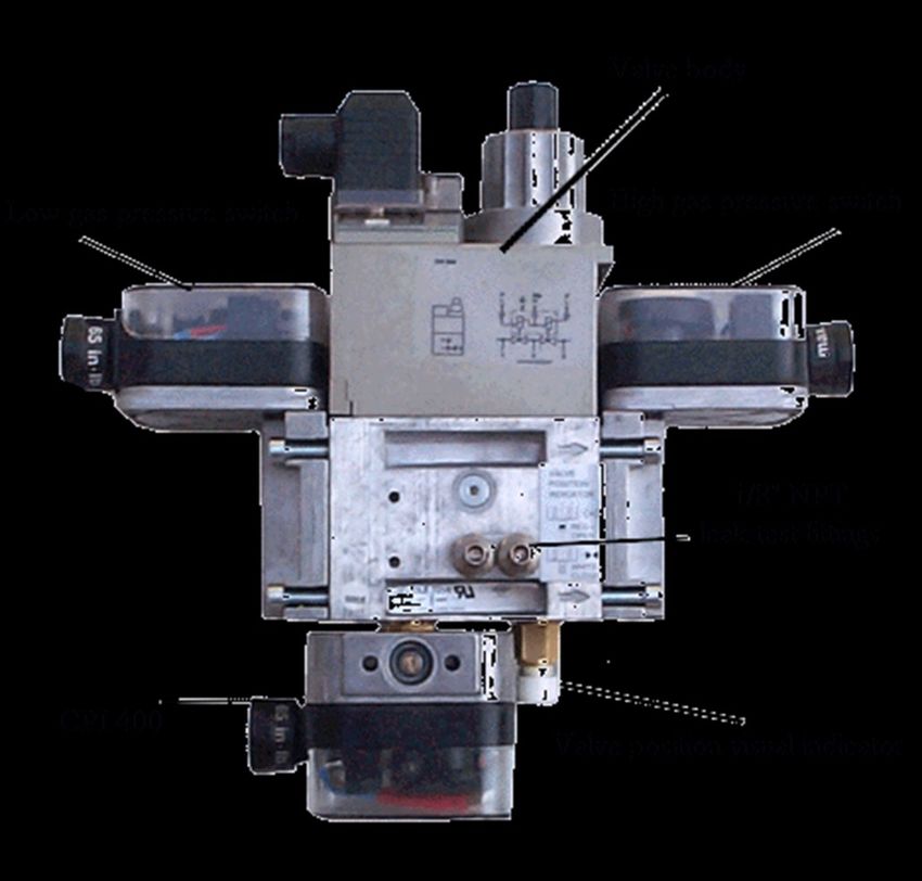
Wet Dog Glass LLC. 2019 Equipment Manual

Warning Symbols

ELECTRICAL ARCS AND EXPLOSION RISK IN HAZARDOUS AREAS
If you connect or disconnect wiring, modules or communications
cabling while power is applied, an electrical arc can occur. This
could cause an explosion in hazardous location installations. Do
not remove wiring, fuses, modules or communications cabling
while circuit is energized unless area is known to be non-
hazardous. Failure to follow these instructions may result in per-
sonal injury.

WARNING- MAINTENANCE
Maintenance must be carried out by people who are experienced
in working on electronic equipment and in particular safety relat-
ed systems. They should have knowledge of and experience with
local operating and safety standards. Failure to follow these rec-
ommendations may result in situations that can lead to system
damage and even personal injury.

WARNING– HEAT
Equipment contains dangerous temperatures. Use caution when
interacting with this equipment. Certain areas of the equipment
may pose a particular hazard, and are marked with this symbol.

                                                                     7
Wet Dog Glass LLC. 2019 Equipment Manual

Warning Symbols

CAUTION- RADIO FREQUENCY INTERFERENCE
Most electronic equipment is influenced by Radio Frequency In-
terference. Caution should be exercised with regard to the use of
portable communications equipment around such equipment.
Signs should be posted in the vicinity of the equipment caution-
ing against the use of portable communications equipment.

CAUTION- HEAT DISSIPATION AND ENCLOSURE POSITION
System and field power consumption by modules and termina-
tion assemblies is dissipated as heat; e.g. enclosures exposed to
continuous sunlight will have a higher internal temperature that
could affect the operating temperature of the modules. Modules
operating at the extremes of the temperature band for a continu-
ous period can have a reduced reliability

CAUTION– CRUSH RISK
Parts of equipment can pose a crush and/or entanglement risk.
Observe caution and best practices. Only trained technicians
may remove safety covers while observing Lock Out Tag Out pro-
cedures.

SPECIAL INSTRUCTIONS- A MANUAL IS PROVIDED
Do not attempt to operate or maintain this Equipment(s) until
you have read and thoroughly understand all of the safety infor-
mation contained in this manual.

                                                                    8
Wet Dog Glass LLC. 2019 Equipment Manual

Receiving and Installation

Unpacking
      Inspect the packaging prior to accepting shipment/package. Report any damage to the appli-
ance as soon as possible, before the driver/delivery person leaves the site. Take pictures and docu-
ment and damages and for posterity.
       A hammer, pry bar, tin snips, and a Phillips screwdriver will be required to remove the crating
from the pallet. Use a 1/2” and/or 9/16” socket wrench to remove the lag screws that hold the ap-
pliance to its pallet. Lift equipment off of pallet with fork lift or similar machinery. Once the appli-
ance is off of the pallet, begin to remove any shrink wrap, being sure to collect any hardware that
may have shaken loose and was captured by the shrink wrap. There may be many items that are
packed on the crate, be aware that everything is accounted for. (This includes thermocouples, door
handle, levelers, related hardware, kiln shelves, etc.)

Installation
       The appliance should be set in place using a pallet jack or forklift. Install and adjust the level-
ing bolts to set the appliance at the desired height and to level the equipment. Do not, however,
raise furnaces more than 1” and other equipment more than 2” as you will run the risk of the level-
ing bolt coming out of the threaded hole. If your appliance is equipped with earthquake floor
mounts, it should be anchored to the floor with appropriate concrete anchors. Any adjustments
made after rigid utility connections to the equipment may cause damage to components. Refer to
spec sheets for weights and dimensions.
        This appliance shall be installed by a qualified service agency in accordance with the manu-
facturer’s instructions and all applicable codes and requirements of the authority having jurisdic-
tion. If the information in these instructions is not followed exactly, a fire, an explosion or produc-
tion of carbon monoxide may result causing property damage, personal injury or loss of life. The
qualified service agency is responsible for the proper installation of this appliance. The installation is
not proper and complete until the operation of the appliance is checked as specified in the manu-
facturer’s instructions supplied with the appliance.

                                                                                                      9
Wet Dog Glass LLC. 2019 Equipment Manual

Receiving and Installation

Installation continued
     Caution: The gas supply shall be shut off prior to disconnecting the electrical power, before
proceeding with the installation.
•Follow industry standard procedures for proper leak testing and torqueing of the appliance prior to
placing it into operation.

•Check to verify that the manifold pressure is correct in accordance with the data tag.

•Check to verify the inlet pressure is within the acceptable range specified by the data tag.

•The appliance and its individual shutoff valve must be disconnected from the gas supply piping sys-
tem during any pressure testing of that system at test pressures in excess of 5 psi.

•The appliance must be isolated from the gas supply piping system by closing its individual manual
shutoff valve during any pressure testing of the gas supply piping system at test pressures equal to
or less than 2 psi.

•Provisions for adequate combustion and ventilation air shall be made prior to starting up the appli-
ance. See spec sheet for recommendations.

•High temperature limit setting shall not exceed the data tag rating.

•The installer shall inform and demonstrate to the user the correct operation and maintenance of
the appliance.

•The installer shall also inform the user of the hazards of flammable liquids and vapors and shall re-
move such liquids and vapors from the vicinity of the appliance.

•Please provide minimal clearance of 2.5 feet from combustible surfaces and 6 inches from non-
combustible surfaces

•Please provide adequate clearances for servicing and proper operation. See the example on the
page. Clearances for each piece of equipment can be found on their respective spec sheets. Cus-
tom configuration clearances will be provided by our design department, but spec sheets can be
taken as an example.

                                                                                                  10
Wet Dog Glass LLC. 2019 Equipment Manual
Receiving and Installation
Generally 24” clearance is required for any component that requires servicing, maintenance , or ad-
justment. This includes clean outs, junction boxes, plumbing, burners, etc. 36” clearance is required
for control panel clearance, and recommended for any component that needs regular interaction,
gas valves and adjustments, plugs, etc. Any access to live electrical components can require 42” of
clearance depending on jurisdiction. See example below.
11Wet Dog Glass LLC. 2019 Equipment Manual
Component Overview
Components that make up Wet Dog Glass Equipment
The following pages are an overview of major components you will find in Wet Dog Glass equip-
ment, and in many kinds of heating applications. Models, brands, and types change regularly to im-
prove price, quality, or add features. Many of these components are functionally interchangeable.
Check your equipment and wiring schematic for the exact component you have. Component manu-
als can be found through the Wet Dog Glass Tech portal, on our website www.wdg-us.com
12Wet Dog Glass LLC. 2019 Equipment Manual
Component Overview
Power Controllers and Relays for Electric Heating Systems
Power controllers (SCRs, SSRs, and thyristors) are typically used for proportional control as they al-
low the temperature controller to use any output percentage from 0% to 100%. These are all solid
state controllers, meaning they have no moving parts.
Power controllers typically function in either with either “on/off” or “phase angle” control logic.
On/Off involves switching on and off at the zero-cross portion of the AC/DC sine wave, resulting in
low electrical noise. This is often used with wire elements. Because phase angle systems switch at
any point on the sine wave, there can be significant electrical noise, typically restricting its use to
certain heating element materials such as molybdenum disilicide and silicon carbide, because their
resistance changes significantly with temperature and age respectively.
Because there are no moving parts, these power controllers can switch on and off faster than any
other type of switch. The result is better, “proportional” control and longer element life. As long as
the power controller stays cool enough, it will last longer than most other types of relays as well.
13Wet Dog Glass LLC. 2019 Equipment Manual
Component Overview
Electric Heating Systems
Contactors
Contactors are used to physical-
ly disconnect power to maintain
user safety or for a specific func-
tion. The contactors in our
equipment, referred to as Defi-
nite Purpose Contactors (DPC),
disconnect the power when the
doors are opened, or when the
temperature passes a high limit.
Safety Relays
These relays are used to monitor
and trigger several actions in the
equipment. Most commonly
they will cause the DPC to open
when the door switch or high
limit are tripped.
Circuit Breakers
These are very similar to what
you find in your service panel at
home. Circuit breakers cut the
power when a high current is
detected, protecting the user
and the equipment. Circuit
breakers are most often found
on large equipment with several
heating circuits or zones.
14Wet Dog Glass LLC. 2019 Equipment Manual
Component Overview
Electric Heating Systems
Fuses and Fuse Holders
Fuses are used to protect cer-
tain components inside the con-
trol panel. Small fuses are used
to protect the control circuit
(Watlow controller, safety relay,
etc) and large fuses may be used
on the power circuit to protect
large and expensive power con-
trollers, such as Din-a-mites and
ePower’s. They also protect
equipment and the user in the
same way as circuit breakers,
but are often faster reacting and
more sensitive.
Door Switch
The door switches senses when
the door has been opened and
causes the DPC to trigger and
cut power while you are gather-
ing (Electric Furnace) or entering
an oven to prevent electrical
shock.
15Wet Dog Glass LLC. 2019 Equipment Manual Component Overview Pressure Regulator Used to reduce and maintain stable pressure at a level that is safe for the operation of components downstream such as safety shutoff valves and proportionating regulators. We do not provide these unless requested. The customers gas fitter/company often provides them. Proportionator - Used for Nozzle Mix Burners (Usually Furnaces) Also known as a ratio regulator, this device uses an air impulse line to maintain an appropriate gas/air ratio over the operational range of the combustion system. It is used to adjust the ratio of air to gas throughout the whole range. This is often the same component, installed differently, as the zero governor. Zero Governor - Used for Pre-mix burners (Usually Glory Holes) Also known as a Balance Zero Regulator (BZR), this device adjusts gas pressure downstream to atmospheric pressure so that a vac- uum from a mixer installed downstream can pull the volume of gas required for efficient combustion. The Zero Governor should not have an air impulse line. It is used to adjust the ratio of air to gas throughout the whole range. This is often the same compo- nent, installed differently, as the proportionator. ALO/AOGC (Adjustable Limiting Orifice/Adjustable Orifice Gas Cock) - High Fire Gas Adjustment This valve is used to limit the maximum amount of gas allowed into the burner at high fire. It allows far finer control than a ball valve. Low Fire Bypass Fitting, attached to the Proportionator. This valve is used to fine tune the gas flow at Low fire. It allows gas to bypass the proportionator, letting a minimum amount to always reach the burner 16
Wet Dog Glass LLC. 2019 Equipment Manual

Component Overview

Variable Speed Blower (VSB)
Most combustion equipment
from Wet Dog Glass, LLC is sup-
plied with a variable speed blow-
er which receives a 0-10VDC in-
put signal from the temperature
controller. The blower speeds up
when the set point temperature
is above the actual temperature
and slows down when the set
point temperature is below the
actual temperature.

Variable Frequency Drive (VFD)
For blowers that do not have
built in variable speed control, a
VFD is used to adjust the speed
of the blower. This is typically
used on larger combustion
equipment only, such as a GH30
custom built furnace.

Manual Butterfly Valve
This valve is used to regulate the
volume and pressure of the com-
bustion air flowing to the burner.
The wider open this valve is, the
higher volume of air will flow, but
the pressure upstream of the
valve will drop. Generally larger
equipment will be set ½ to ¾
open, while smaller equipment
will be set ¼ to ½ open.

                                           17
Wet Dog Glass LLC. 2019 Equipment Manual
Component Overview
Flame Supervision
Electronic flame supervision is required on all combustion equip-
ment over 150,000 BTU’s by NFPA 86. Up until 2015 we used Veri
-Flame and have since switched to the MPA. These units monitor
various safety sensors and moderate the combustion operation
including startup and shut down procedures.
Dual Valves
The dual valves are two solenoid valves that work together to en-
sure safety. When the MPA detects a fault from one of the sen-
sors, it will close the valves. When the fault has been corrected
and the system is reset, the MPA will open the valves and allow
gas to the burner after the startup sequence.
UV Scanner
The UV scanner detects when flame is present and relays this
information to the MPA. This can also be accomplished by a
flame rod, which is less expensive but requires more frequent
replacement and maintenance.
Air Pressure Switch
The air pressure switch detects whether the air line has pressure
and relays this information to the MPA. No pressure indicates
the butterfly valve has been closed or the blower is not function-
ing.
Gas Pressure Switches
The high and low gas pressure detect if the gas pressure is above
or below their set points and relays this information to the MPA.
18Wet Dog Glass LLC. 2019 Equipment Manual
Critical Components In Depth
KDI Dual Valve Assembly
Below is an example of a KDI Dual Valve Assembly. Components may be mounted in a different ar-
rangement than shown here.
The high and low gas
pressure switches will
shut the system down
if they detect gas
above or below their
set points.
The CPI 400 is a manual
position indicator. It con-
firms that the valve is truly
closed or open. Only re-
quired on equipment This valve body con-
400,00 BTU and over tains two valves.
The reason for this is
that if one fails to
close or gets stuck,
there is a second to
shut the gas flow
19Wet Dog Glass LLC. 2019 Equipment Manual
Critical Components In Depth
KromSchroder Dual Valve Assembly
Below is an example of a KromSchroder Dual Valve Assembly. Components may be mounted in a
different arrangement than shown here.
The high and low gas
pressure switches will
The POC is a manual posi- shut the system down
tion indicator. It confirms if the detect gas above
that the valve is truly or below their set
closed or open. Included
by default on all KS Valves
This valve body con-
tains two valves.
The reason for this is
that if one fails to
close or gets stuck,
there is a second to
shut the gas flow
20Wet Dog Glass LLC. 2019 Equipment Manual
Critical Components In Depth
Temperature Controllers
Temperature controllers are the component you will most often use on your equipment. Watlow
controllers are what we primarily use, and what you will see most often on glass equipment. These
are called PID controllers. They look at the temperature you want to get to, called setpoint, and the
temperature the equipment is currently at, called process value, and figures out the most efficient
way to do that. If you’re only a few degrees low, you don’t want the burner to blast to 100%.
While these controller have many settings in them that the average user will never need to adjust,
here are a few that will help you understand what it’s doing, and that you may want to change de-
pending on your use.
Manual vs. Auto Control Mode
The control mode is something you may never change on an electric oven, but is often used
when tuning combustion equipment. When in auto you tell the controller the set point, and it de-
cides what % to be at to get there or maintain that temperature. When in manual you set that % di-
rectly. For tuning this keeps the blower at the same speed, which lets you adjust the gas to be a
good neutral flame.
The other option in this setting is Off, which will stop the controller entirely. On electric equip-
ment this is the same as 0%, but on combustion equipment this will turn the blower off entirely (0%
for a blower is still on, just barely).
Proportional Band
This is the setting that decides how big of a range the controller ramp powers in when not at
0% or 100%. For example, with a proportional band of 50 degrees whenever the process value is
more than 50 degrees from set point the controller will be at 0% or 100%. When within 50 it will
begin ramping up (or down) so that it does not overshoot the setpoint. With too small a proportion-
al band your equipment will bounce around too much as it tries to maintain the setpoint. When too
large, the equipment will be slow to go up or down because it doesn’t stay at 0% or 100% for long
enough.
21Wet Dog Glass LLC. 2019 Equipment Manual
Critical Components In Depth
Temperature Controllers
22Wet Dog Glass LLC. 2019 Equipment Manual
Critical Components In Depth
Temperature Controllers
23Wet Dog Glass LLC. 2019 Equipment Manual
Critical Components In Depth
Temperature Controllers
It is often helpful to take pictures of any error codes or questionable
settings so that they can be correctly interpreted later.
The Setup Page is password protected to protect
against accidental changes to programming. To
unlock the controller hold reset and advance until
ULoC, FCtY is displayed. Press the advance key
twice to see PASS on bottom. Use the arrows to
change the top number to 156. Press the reset key
twice to return to the home screen. The controller
will stay unlocked until you go back to this screen
and change 156 to another number, or until power
is cycled to the controller.
24Wet Dog Glass LLC. 2019 Equipment Manual
Critical Components In Depth
Temperature Controllers
Changing Control Mode
Depending on the generation of controller you have, this
will appear in two different formats.
2019 and Newer Equipment
On combustion equipment, press the green advance key
once and you will see the current heat percentage on top and the
current control mode on bottom. On electric equipment, press
the green advance key several times until you see the same
screen.
Use the arrows keys to cycle between “AUto”, “Man”,
“oFF”. Once selected, hit the reset (infinity) key to go back to the
main screen. This will show either a temperature (auto) a per-
cent (manual) or off in the bottom and the current temperature
on top.
2019 and Older Equipment
On combustion and electrical equipment, press the green
advance key several times until you see the current control mode
on top and C.M1 on bottom. Use the arrows keys to cycle be-
tween “AUto”, “Man”, “oFF”.
Once selected, hit the reset(infinity) key to go back to the
main screen. This will show either a temperature (auto) a per-
cent (manual) or off in the bottom and the current temperature
on top
25Wet Dog Glass LLC. 2019 Equipment Manual
Critical Components In Depth
Temperature Controllers
Writing a Profile
There are several important things to understand before starting on writing profiles.
•Watlow PM controllers have 40 possible “steps” split into 4 profiles of 10 steps each
•Profile 1 uses steps 1-10, profile 2 uses steps 11-20, profile 3 is steps 21-30, profile 4 is steps 31-40.
•Always attend a piece of equipment when running a profile for the first time or after changes, to be
sure it is doing what you want.
While profiles can become very complicated, 3 kinds of steps are primarily used; Soak, Time and
End. All steps default to unused (UStP) and should be set to this when not wanted.
Soak (SoAh) holds the current set point for the amount of time you specify before moving onto the
next step
Time (ti) moves the set point from its current value to the temperature you specify over the amount
of time you specify.
End ends the profile, and allows you to choose what happens to the set point once the profile is
over.
Use the chart on the next page to plan your profile, and refer to it as you enter the profile into the
controller. The profile shown is the basic annealer profile preload onto oven controllers.
26Wet Dog Glass LLC. 2019 Equipment Manual
Critical Components In Depth
Temperature Controllers—Example Profile
This is a basic annealing profile that comes as the default for profile 1 in our annealing and casting
ovens. We suggest adjusting the times and temperature to fit your glass and work.
Step 1 takes the set point to 900 in one second, so that the oven gets back to annealing temp after
losing some heaT from opening the doors to put the last piece of glass in.
Step 2 soaks at that 900 set point for 3 hours.
Step 3 goes from 900 to 800 over 3 hours
Step 4 goes from 800 to 690 over 3 hours
Step 5 goes to room temp over 2 hours (Usually the profile outpaces the ovens cooling during this
step, and the oven cools naturally)
Step 6 ends the profile and leaves the set point at 70.
Step # S.tYP t.SPl hoUr Min SEC End Ent1, 2
Step Type Target Setpoint
1 ti 900 0 0 1 N/A N/A
2 SoAh N/a 3 0 0 N/A N/A
3 ti 800 3 0 0 N/A N/A
4 ti 690 2 0 0 N/A N/A
5 ti 70 2 0 0 N/A N/A
6 End N/A N/A N/A N/A Hold N/A
7 UStP - - - - - -
27Wet Dog Glass LLC. 2019 Equipment Manual
Critical Components In Depth
Temperature Controllers
Entering a Profile into the controller
Begin by holding the green button until you see P1 on top and ProF on bottom. The arrow
keys will cycle you through P1-P4. Select the profile to be edited, and press the green button
You’ll now see 1 on top and P1(or P2,3,4) on bottom. The top number is the step selected.
Use the arrows to select the step to be edited and press the green button.
This is the final menu level where settings are changed. The green button cycles through the
available settings on the bottom screen, and the arrows change the setting on the top screen. Using
the example profile, the display after selecting P1, and Step 1 should be S.tYP on bottom, and SoAh
on top. The arrows change the step type, and the green button advances to the next option. When
all the parameters of the step are set, press the reset button to return to the step selection screen.
It often helps when writing a new profile to set all steps for 10 seconds, so the profile can be
run and tested to make sure it is working properly, then change the times to the correct amounts.
Starting, ending, and pausing a Profile
From the main screen, press the advance key (green) until P.St 1 (Profile Start) appears on bottom
and a number on top. The number on top is the profile or step to be started, pasued, or ended.
Press the advance key to move on to P.AC 1 (Profile Action). Select ProF on the top screen to
start profile 1-4. Select StEP to start at step 1-40. PAUS will pause the currently running profile at its
current step and set point, rESU resumes it. End ends the currently running profile. When the ac-
tion has been selected on the top screen, press reset to return to the home screen. A graph icon on
the right side of the screen indicates a profile is running.
When a profile is running, the current step type, and time remaining (CSP, S.tYP, hour, min,
sec), can be seen by cycling through the home screen with the green key, only on controllers in 2019
equipment and newer.
28Wet Dog Glass LLC. 2019 Equipment Manual
Critical Components In Depth
Temperature Controllers
Watlow F4T touchscreen Controller
The Watlow F4T has very similar workings to a Watlow PM controller. Profiles work the same
way, all the settings are identical, etc. The F4T uses real words rather than abbreviations, and allows
for equipment with multiple heating zones far more conveniently than the PM controller.
All of the information in the previous section still applies. The F4T is also password protected.
Because of the ease of use, it is also far easier to change settings that should not be changed. The
F4T will come with a USB containing WDG’s base configuration. Its suggested to leave this as is, in
case of a setting change that causes any problems. Files can be exported and imported, allowing a
profile written on one controller to be transferred to several others.
First level of access: UwP
Second Level of access: MUP
29Wet Dog Glass LLC. 2019 Equipment Manual
Critical Components In Depth
Flame Supervision
Eclipse “Veri-Flame” and Dungs “MPA”
The Veri-Flame and MPA flame supervision modules are inte-
gral to the flame supervision process. Wet Dog Glass used the Veri-
Flame exclusively from 1996 into 2015, eventually replacing it with
the KDI MPA when it became important to comply with regulations
internationally and to communicate with them remotely. These units
monitor various safety sensors and moderate the combustion opera-
tion including startup and shut down procedures. The typical user
will rarely interact with these to units other than to reset them or
read status or error codes.
The general sequence of operations is as follows:
1) System check: Safety shutoff valves should be closed, air pressure switch should be open (no a
pressure detected), UV signal should not exist, and interlocks loop (consisting of high and low gas
pressure switches, high limit switch, and any other switches such as a ventilation interlock or CO
sensor)
2) Pre-purge: The blower alone is energized and purges the combustion chamber including ports
and flues to clear any gas from the atmosphere. During this phase,
the air pressure switch must sense air and close. The default pre-
purge duration is 30 seconds, but essentially the entire interior vol-
ume of the equipment must be replaced 4-5 times (depending on
regional codes) with fresh air during this period.
3) Trial-for-Ignition (TFI): If present, a pilot safety valve opens
while the spark plug is energized: to ignite the flam, and the UV
scanner is expected to detect a flame within 5-15 seconds depend-
ing on regional codes. If no pilot valve is used, the main safety
shutoff valves will open at this time. In some cases, ignition is per-
formed manually during the TFI. If no flame is detected within the
TFI period, the system shuts down and must be reset.
4) Operation: If a flame is detected during the TFI, the main safety shutoff valves open, and the sys-
tem will fire until it is interrupted by either the operator or the flame supervisor due to any system
sensors becoming unsatisfied. If the flame signal is too weak or lost at any point, the system will
shut down within 1-3 seconds depending on regional codes.
5) Shutdown: The Veri-Flame’s LED indicators and MPA’s digital display will indicate system status or
error codes which can be cross-referenced in the troubleshooting section of this manual.
30Wet Dog Glass LLC. 2019 Equipment Manual
Critical Components In Depth
Flame Supervision
Dungs (KDI) MPA Flame Supervision
Heat Request Flame On Fault
Blue Yellow Red
Reset/Confirm
Minus, Decrease Plus, Increase
Back
setting value setting value
Quick Displays:
Plus and Back: Error memory
Hold Reset for 4 seconds for hard reset, in case of F04 error
Plus and Reset: Info Display, UV Scanner Signal
Minus and Back: Resets display to normal
31Wet Dog Glass LLC. 2019 Equipment Manual
Critical Components In Depth
Flame Supervision
MPA Error Codes. It often helps to take pictures of error codes for ease of use later, as you will
often be trying to restart the equipment immediately.
Display Code Other symptoms Possible cause Remedy
1 -Blower running, -Air pressure switch not confirming -Clean air inlet filter, check air
MPA doesn’t go to air pressure due to: Clogged air inlet line for clogs, open three way
next step to initiate filter, clogged air line, three way air outlet valve, pop relay coil out
trial for ignition outlet valve closed, relay stuck, and re-insert into relay body,
loose wires check for loose wires
FA2 -System shut down -Gas pressure too low or too high -Check gas pressure—has pro-
during operation -insufficient gas pressure at inlet pane tank run out of gas, has
-burners backfiring natural gas service been cut off?
-temperature limit not satisfied: All valves open? Regulator
temperature out of range, loose or needs adjustment?
failed thermocouple or connections -Has there been an issue with
-When a CO monitor or ventilation backfiring in the premix burn-
system is tied in, this error can be ers?
caused --Check thermocouple connec-
tions.
FA6 Flame detected out -UV scanner is defective or is de- -Replace UV Scanner
of sequence (when tecting light from another source -Remove other light source
not expected) -ground connection on a flame rod -Remedy ground connection on
-user inserted lighting torch too ear- flame rod
ly -Wait until the valves open with
a click, blue light, or red indica-
tor to insert torch
FA7 -System shuts down -Failure to establish flame -Adjust gas/air mixture
prior to establishing -Failure to detect established flame -Check wiring to gas valves
flame -Gas safety shutoff valves did not -clean/replace spark plug
open -Swap L1 and N connections in
-Ignition spark plug dirty or has wiring base (of monitor)
faulty wiring -Replace UV Scanner
-Mixture too lean or rich to establish -Check UV sight lines
flame
-Faulty UV Scanner
FA8 System shuts down -Flame failure -Adjust gas/air mixture
during operation -Failure to detect established flame -Replace UV Scanner
-Mixture too lean or rich to maintain -Test UV Scanner, (Return and +
established flame button to show flame strength
-Faulty UV Scanner signal) 0-58
F13 System shuts down -Blower still running after previous -Wait for blower to stop run-
or doesn’t start up shutdown ning prior to reset
-Low gas pressure switch trips when -Remedy pressure drop in pip-
gas valves open. ing upstream of low gas pres-
sure switch
-Regulator may need adjust-
ment or replacement
-high or low gas pressure switch
may need adjustment
32Wet Dog Glass LLC. 2019 Equipment Manual
Critical Components In Depth
Flame Supervision
MPA Error Codes continued:
FAA Air flow detected -Air pressure switch defective -Replace air pressure switch
out of sequence -Blower has not stopped turning -Wait for blower to stop com-
(when not ex- completely after shut down pletely
pected) -Air flow from another source -Restrict air flow from other
-Air pressure switch set incorrectly source
-Set air pressure switch correct-
ly
FAb Air Failure -blower filter is clogged -Clean filter
-valve in air piping is closed -open valve (not the butterfly
-air piping has a major leak valve unless it has fully closed.
-control signal to blower is interrupt- —look for another valve to
ed or insufficient open)
-power to blower is interrupted or -repair leak in air piping
insufficient -restore control signal
-blower rotor is locked -restore power supply
-Air blower has failed -remove debris to unlock rotor
-replace blower
Fb6 At startup, gas safe- -Proof of Closure switch not satisfied -check power to safety shutoff
ty shutoff valves -safety shutoff valve failure valve during trial for ignition
never open or they -power to safety shutoff valve inter- -reconnect/tighten any loose
open then shut rupted wires in the safety shutoff valve
-wires have come loose assembly
-check adjustment of micro-
switch in Proof of Closure mod-
ule on valve
33Wet Dog Glass LLC. 2019 Equipment Manual
Critical Components In Depth
Thermocouples
A thermocouple is an electrical device consisting of two dissimilar electrical conductors form-
ing electrical junctions at differing temperatures. A thermocouple produces a temperature-
dependent voltage as a result of the thermoelectric effect, and this voltage can be interpreted to
measure temperature. Thermocouples are a widely used type of temperature sensor.
The most commonly used types of thermocouples in glass equipment are Type K, and Type R/
S.
Type K thermocouples are good up to 1350 Celcius, but fare poorly in reduction. Hydrogen
formed in reduction atmospheres causes oxidation and reduces the accuracy of the thermocouple
and causes them to read low. As some hydrogen is always present in gas fired systems, type K ther-
mocouples are not the best choice. They can be used, but will age quickly, have temperature drift,
and need regular replacement.
Wet Dog Glass uses Type K thermocouples in electric ovens, and in gas equipment such as
garages that are less temperature critical.
Type R/S thermocouples are far more stable than type K and will not age and degrade quickly
in reduction. They can be used up to 1600 Celsius. While expensive, the expense is primarily in the
metals used in construction, so broken or non-functional thermocouples can be returned to the
manufacturer for a steep discount on new thermocouples.
When installing or servicing thermocouples, remember that different types are not inter-
changeable and if they are wired backwards, the temperature will read backwards.
34Wet Dog Glass LLC. 2019 Equipment Manual
Initial Setup and Turn On
Electrical and Gas Connections
Electrical and gas connections are required to be made by
the customers licensed tradespersons.
Combustion Systems:
Most combustion systems require 120v supply. Inside the
control panel are 3 terminals labeled “L, N, PE”. The licensed
tradesperson will connect to these terminals. All supply, distribu-
tion, and control to various components (Blower, valves, etc) is
built into the equipment. The required/designed for voltage,
phase, frequency, and current usage can
be found on the data tag.
The BTU/hr and inlet pressure
ratings can be found on the data tag on
the control panel. Gas supply must meet
these requirements. Regulators are
often needed to step down LP tank pres-
sure to a usable range.
Electrical Systems:
Most electrical systems require
240v 1ph, 208v 3 ph, or higher voltages.
Inside the control panel is a distribution
block labeled “L1, L2, L3” and a ground-
ing lug with the PE symbol. The licensed
tradesperson will connect here. All supply, distribution, and con-
trol to various components (Elements, controller, fans. Etc.) is
built into the equipment. The required/designed for voltage,
phase, frequency, and current usage can be found on the data
tag.
Remote Mounted Control Panels:
When a remote mounted control system is requested, the
set-up becomes more customized per system. Details of the con-
nections required can be found in the wiring schematic for the
equipment.
35Wet Dog Glass LLC. 2019 Equipment Manual
Initial Setup and Turn On
Electric Furnaces
Electric Furnaces require more setup than other Equipment. Once the furnace, control panel, and
transformer are in place, electrical connections must be made. Power must be supplied to the con-
trol panel from the customers supply. Power wires a run between the control panel and transform-
er, and then from transformer to the furnace’s element junction box. Control wiring for the Air pres-
sure switch, cooling blower, door switch, and thermocouples is run between the control panel and
the furnace’s control junction box.
THESE CONNECTIONS MUST BE MADE BY A LICENSED ELECTRICIAN, AND IN ACCORDANCE TO THE
SPECIFICATIONS IN THE FURNACE WIRING SCHEMATIC. DEVIATION FROM THIS WIRING SCHEMAT-
IC CAN CAUSE DAMAGE TO THE FURNACE AND LEAD TO UNSAFE CONDITIONS.
Torque all power circuit connections. Existing connections should be torqued once. New connec-
tions made by your electrician should be torqued twice, with 48 hours in between torqueing.
36Wet Dog Glass LLC. 2019 Equipment Manual
Start up for Combustion Furnaces
Control Components Overview
Wet Dog Glass Furnaces most often use a nozzle mix burner in tandem with a variable speed blower
and temperature controller. The user assigns a set point temperature, and the controller will ramp
the blower up and down to achieve that temperature. The user has four adjustment points to bal-
ance the gas and air: FRG (Gas/Air proportionator), the Adjustable Limiting Orifice or Needle Valve,
the low fire bypass, and the butteryfly valve for air.
FRG: Also called the proportionator or ratio regulator. Primarily use to change the amount of
gas in the low-fire and mid-fire range. Remove the small black cap and adjust with flathead screw-
driver. Clockwise allows more gas through, counter-clockwise allows less.
Low Fire Bypass: Located on the side of the FRG, small flat head under black cover. This al-
lows a small amount of gas through without the influence of the FRG, used for low fire adjustment.
Clockwise for less gas, counter-clockwise for more gas.
ALO, Needle Valve: This valve is located just before the burner and limits the maximum
amount of gas at high-fire. Remove the cap to find a recessed flathead screw. Clockwise decrease
gas, counter-clockwise increases gas (Opposite of FRG)
Butterfly Valve: This valve is located on the cold air line just before the recuperator. While it
primarily allows more or less air through, it also affects the amount of gas allowed into the system
by the FRG. Small changes here have a very large effect. Closing the valve decreases the air but also
increases the gas, and vice-versa. The butteryfly valve should be set to 1/2 for startup, and only ad-
justed in necessary. You will likely never adjust it again.
37Wet Dog Glass LLC. 2019 Equipment Manual
Start up for Combustion Furnaces
Heat Up Process and Schedule
Start with the FRG at about half (Factory setting), the ALO valve open a half turn, and the
butterfly valve half way open (45 mark on new butteryfly valves). To set the ALO, close it entirely,
then open a half turn, this will be closer to a full turn on large furnaces (RDT1000). Air will need to
be bled from the lines the first time, and the equipment may need to run through its startup se-
quence several times to do so. Set the Watlow controller to manual and set to 15%
The blower will run for a 30 second purge, then the DSSOV (Dual Safety Shut-off Valves) will
click open. KDI Valves have indicators that turn red when the valves open. Kromschroder valves
have blue lights that indicate open. When the valves open, the spark plug will begin sparking inside
the nozzle to ignite the burner. If the system does not start within the allotted time the valves close
and an error is displayed on the MPA. Press reset to begin the ignition procedure again.
When the Furnace is lit, adjust the ALO clockwise towards less gas until you reach the small-
est stable flame possible. Look through the peep sight on the burner to observe the flame as you
turn. The Watlow controller will be kept at 15% throughout the heat up process. The first hour will
go faster than the schedule. Furnaces usually after an hour or two between 200-300F, at which
point proceed below.
As the furnace heats up, follow this warm up schedule manually by opening the ALO slightly
each time the furnace slows down or stalls out. A very slight turn (1/8th) will accomplish this, with
larger turns needed as the furnace gets hotter. You should reach ~1900 without changing the blow-
er speed. This process is done manually and cannot be accomplished by a profile. If turning the
ALO no longer causes adequate temperature increases, you can also increase the gas flow by turning
both the FRG and ALO. This is sometimes needed above 1000F.
For pre-fired castings: (All WDG Furnaces): 25 degree an hour rise. It is acceptable to go fast-
er and slower than this and average 25 an hour. The most critical period to go no more than 25 an
hour is 1000-1300 F.
Once you reach 1900-2100, the furnace can be tuned for the first time. The tuning will
change as we get to your normal working range, and will change once some glass is in the pot. For
the initial tune, the furnace should be able to heat up when the blower is set to 100% and cool down
when set to 0%, with no large amounts of reduction at any point. Do not spend too much time with
this first tune, as things will change as your temp increases. We recommend doing the initial tune
quickly, and tweaking it over the following week as you get glass in the pot and go through a few cy-
cles.
38Wet Dog Glass LLC. 2019 Equipment Manual
Start up for Combustion Furnaces
Tuning Overview
Tuning is the process of balancing the air and gas so the flame is close to neutral, neither too much
gas nor too much air. A neutral flame is the most efficient. Extra gas (Fatty) causes reduction and
wastes gas. Extra air (Lean) counteracts heat, putting unneeded cold air into the furnace.
The temperature controller automatically controls the amount of heat going into the furnace by
changing the blower speed. The FRG (proportionator) increases or decrease the amount of gas ac-
cording to the amount of air. A small impulse line carries air pressure from the cold air line before
the butteryfly valve to the proportionator. This air pressure pushes down a diaphragm that is
attached to a valve inside the FRG. The more the diaphragm is pushed down, the more the valve
opens, letting more gas through. This is the primary control process that keeps the flame near neu-
tral, whether at low fire (minimal blower speed and small flame) or at high fire (maximum blower
speed and large flame) and everywhere in between.
The FRG does not provide perfect ratio control however, which leads to the tuning process and
multiple components to adjust gas flow.
The FRG has an adjustment screw that will causes a spring to press more or less on the diaphragm,
biasing the FRG towards more or less gas throughout the whole range from low fire to high fire.
Clockwise (CW) is more gas, Counter Clockwise (CCW) is less gas. This is opposite of the other ad-
justments.
The low fire bypass mounted on the side of the FRG bypasses a small amount of gas around the
FRG, allowing more or less gas to the burner unaffected by the FRG. This is used for adjusting gas in
low fire, and has very little affect to the flame over 20% blower speed. Clockwise (CW) is less gas,
Counter Clockwise (CCW) is more gas.
The ALO (Needle Valve) is the last component before the burner, and thus limits the maximum
amount of gas that the FRG provides to the burner. This is used to increase or decrease the amount
of gas at high fire only. Clockwise (CW) is less gas, Counter Clockwise (CCW) is more gas.
The Butteryfly Valve changes the amount of air going to the burner, but it also changes the amount
of air pressure going to the FRG. When the butteryfly valve is opened, more air goes to the burner
but the impulse line pressure decreases causing the FRG to let less gas through. When the butteryfly
valve is closed, less air goes to the burner but the impulse line pressure increases causing the FRG to
let more gas through. The butterfly should only be changed from 1/2 open if the other adjustments
are not adequate for the following tuning process.
39Wet Dog Glass LLC. 2019 Equipment Manual
Start up for Combustion Furnaces
First Tuning
When performing the initial tuning for startup of a furnace, be aware of your temperature. It is
best to get the furnace above 2000 and stabilize it there manually. Let it soak for several hours so
heat can soak into the castings. Tuning too quickly and having the temperature jump dramatically
during startup can lead to cracked castings. If temp is getting out of hand, turn the % down to 0-
10% and let the furnace stabilize back to ~2100.
Changes to gas and air take 5-30 seconds to be apparent, quickly at high fire and slowly at low fire.
Always pause between adjustments to wait and check for the result. A neutral flame is achieved
by increasing the gas until you see a small amount of flame from the door or flue, then decreasing
the gas until that flame just goes away. If you have a tight fitting door, try opening the door and
watching for a small amount of flame that appears when the door is opened and then disappears.
If these flames are small and go away quickly, you are close to a neutral flame.
Step 1 (Tuning during initial startup) — Change the Blower speed on the Watlow controller to 30%.
Turn the ALO counter clockwise for more gas 4 full turns. The ALO will no longer be limiting the gas
flow. If you see any flame from the door or flue, turn the FRG (proportionator) counter clockwise by
1 full turn increments, waiting for ~20 seconds between turns and checking for flame. When the
flame goes away, stop. If you don’t see flame, turn the FRG (proportionator) clockwise by 1 full turn
increments, waiting for ~20 seconds between turns and checking for flame. Once you see flame,
turn counterclockwise until the flame goes away. This process will get the proportionator close to
it’s final adjustments. The temp should now be going up faster than before.
Step 2 — Change the blower speed to 0%. If there is flame out the door or flue, turn the low fire by-
pass clockwise to decrease gas. Use 1 full turn increments, waiting ~20 seconds between turns and
checking for flame, stop when the flame goes away. If there is no flame out the door, turn the low-
fire bypass counter clockwise to increase gas. Once you see a lick of flame, back off the gas slightly
until the flame goes away. If the low-fire bypass becomes maxed in either direction, you can adjust
the proportionator (FRG) to achieve more or less gas. Make sure the temperature drops when the
blower is at 0%, if the temp is not dropping, or dropping very slowly, decrease the amount of gas.
40Wet Dog Glass LLC. 2019 Equipment Manual
Start up for Combustion Furnaces
First Tuning
Step 3 — Change the blower percentage to again stabilize the furnace at ~2100. 50% should in-
crease the temp and 0% should decrease the temp. This step involves taking the furnace to high fire
and should be done quickly to not shock the castings during their first time hot. Tweaking can be
done later on to finalize this tuning. At high fire (100% blower speed), changes made to gas take
effect quickly.
Change the blower speed to 100%. If there is flame out the door or flue, turn the ALO clock-
wise to decrease gas until the flames go away. If there is no flame out the door or flue, turn the ALO
counterclockwise to increase gas. Once you see a small amount of flame, decrease the gas until the
flame just goes away. The temperature should be rising rapidly. Change the blower to 0% to stop
the temperature rise.
Step 4 — Change the blower percentage to again stabilize the furnace at ~2100. Once stabilized,
change the blower percentage to 50% and observe for flame from the door or flue. If you see any
flame from the door or flue, turn the FRG (proportionator) counter clockwise by 1 full turn incre-
ments, waiting for ~20 seconds between turns and checking for flame. When the flame goes away,
stop. If you don’t see flame, turn the FRG (proportionator) clockwise by 1 full turn increments,
waiting for ~20 seconds between turns and checking for flame. Once you see flame, turn counter-
clockwise until the flame goes away. Change the blower percentage to again stabilize the furnace at
~2100.
Step 5 — Now that the tuning is approximately correct, change the Control Mode to AUTO. Change
the setpoint to 2150, or 50 degrees above your current temp. Press the green button on the con-
troller will allow you to see the percentage of the blower as the furnace goes to the set point. Take
note of how long the furnace takes to get to the specified temp and the % it uses. Let the furnace
maintain the temp for ~10 minutes to stabilize. The % should slowly drop as the castings warm up.
Change the set point back to 2100, or 50 degrees below current temp. This step is to confirm that
the furnace can rise or lower to its setpoints and maintain its setpoints without issue.
41Wet Dog Glass LLC. 2019 Equipment Manual
Start up for Combustion Furnaces
First Tuning
Step 6 — With the furnace now able to run in auto, drop temp, raise temp, and maintain; It’s time to
start adding in glass. We recommend starting with very small charges, ~10 lb’s, until you have about
an inch of glass in the bottom of the pot. You can then add larger charges, but make sure they are
small enough to keep the cold charge in the center of the pot without touching the walls. We rec-
ommend using preheated glass for these first few charges to lessen heat shock on the pot. Future
charges will always have a layer of hot glass between them and the crucible, providing a barrier be-
tween direct contact of cold glass and the crucible. As the furnace fills with glass and the castings
reach a stable level of heat, the tuning may shift and need tweaks. Pay close attention to the furnace
in its first few weeks running and make adjustments as needed to maintain a good neutral flame.
Follow the next Tuning Walkthrough for a simplified version to be performed any time.
We recommend tuning in the morning, so you can observe the furnace throughout the day. Try
running the furnace through a shortened charge, melt, squeeze, work cycle. This will help you
spot issues, such as not cooling quickly enough (Make the low fire leaner) or heavy reduction at
certain percentages (If in the middle range, decrease gas at the FRG. If at high-fire decrease gas at
ALO)
Follow the “First Charge” Procedure in the Charging and Melting section of this manual. It is im-
portant start slowly to prevent stress to the liner or crucible.
42You can also read