APL JANUS System Progress on Commercial Suborbital Launch Vehicles: Moving the Laboratory Environment to Near Space - Sciendo
←
→
Page content transcription
If your browser does not render page correctly, please read the page content below
Research Note • DOI: 10.2478/gsr-2021-0003 GSR • 9 • 2021 • 30–49

                   Gravitational and Space Research

                   APL JANUS System Progress on Commercial
                   Suborbital Launch Vehicles: Moving the Laboratory
                   Environment to Near Space
                   H. Todd Smith1, Ryan T. Hacala1, Erik M. Hohlfeld1, Weston K. Edens1, Charles A. Hibbitts1, Larry J. Paxton1, Steven P. Arnold1,
                   Joseph H. Westlake1, Abigail M. Rymer1, Al Chacos1, Mason A. Peck1, Ben R. Zeiger2

               1
                   The Johns Hopkins University Applied Physics Laboratory, Laurel, MD; 2Luxel Corporation, Friday Harbor, WA
Abstract
               Multiple private companies are building suborbital reusable launch vehicles possessing vastly different designs. Many of
               these companies originally focused on space tourism; however, revolutionary applications for scientific and engineering
               research as well as technology demonstrations and instrument development are emerging. The dramatic reduction in
               cost over traditional launch systems as well as a guaranteed (and rapid) safe payload return enable many new launch
               vehicle applications. These new capabilities will essentially move the laboratory environment up to the edge of space.
               To make use of these novel launch vehicles, the John Hopkins University Applied Physics Laboratory has established a
               Commercial Suborbital Program with a core system (JANUS) to support and enable many future suborbital missions. This
               program has already conducted six suborbital flight missions to establish vehicle interfaces and analyze the suitability
               and limits of each flight environment. Additionally, this program has also been selected by the NASA Flight Opportunities
               Program for five additional operational suborbital missions. Here we present the results of our completed missions as well
               as descriptions of future selected missions scheduled for 2021–2023.

Keywords
               Commercial Suborbital • JANUS • NASA Flight Opportunities • Blue Origin • Virgin Galactic • Masten Space Systems

INTRODUCTION

In recent years, several companies have actively developed                                  First, the cost of flying payloads on these launch vehicles
both manned and unmanned fully reusable suborbital                                     is over an order of magnitude lower than the traditional launch
vehicles of various designs and capabilities to provide routine                        systems (Jurist, 2009). Such a reduction in cost facilitates
access to near-Earth space. As an indicator of their rise in                           space access for many smaller or nontraditional organizations
prominence, there has been an upsurge in commercial                                    as well as enables lower cost and more frequent opportunities.
spaceport infrastructure to support these vehicles. This has                           Next, sRLV companies are planning for routine and rapid flight
led to many states vying to establish spaceports to potentially                        cadence allowing for more responsive flight tests. Perhaps most
host many of the planned suborbital activities. There has also                         significantly, these vehicles offer both a gentle launch and a safe
been tremendous international interest, with spaceports being                          return of payload, often only a few hours after the flight. This is an
discussed or planned for overseas operations. This is clearly                          entirely new capability that enables flight of low cost, prototype
an exciting time to be involved in the growing suborbital                              payloads that can be flown iteratively, generally beyond what is
industry. The exact nature of the flight path, the altitudes to be                     achievable with NASA’s traditional suborbital portfolio. Over the
reached, and the duration of the flight vary for each suborbital                       last 10 years, we have found that this capability is effectively
Reusable Launch Vehicle (sRLV) vendor. In general, these                               raising the laboratory environment to the edge of space. This
vehicles achieve altitudes >100 km, and they provide on the                            emerging capability also offers the opportunity to fly “human-
order of a few minutes in a low gravity environment. Initially,                        tended” payloads on these vehicles where researchers will be
sRLV companies solely targeted space tourism as their                                  able fly with their experiments further creating an analogy to
primary source of income. However, it has become evident                               the laboratory environment as well as opening up new research
that these new vehicles offer game-changing opportunities for                          strategies.
scientific research, engineering development, and education                                 Many applications for these new spacecraft are only starting to
as well.                                                                               evolve and emerge. The opportunities for revolutionary scientific

†
    Corresponding author: H. Todd Smith
E-mail: h.todd.smith@jhuapl.edu

                                                                                                                                                     30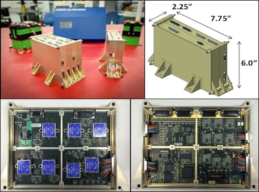
Gravitational and Space Research

research at ~100 km are truly novel. This atmospheric region,          participating in this surge of suborbital activities over the past
which reaches up to the lower edge of Earth’s ionosphere,              10 years. Through these activities, APL has developed closer
informally referred to as the “ignorosphere,” has been difficult       relationships with vendors that help educate these companies
to explore using in situ instrumentation because it is too high        on the significant research and engineering potential of their
for high-altitude balloons and aircraft, and too low for traditional   launch vehicles as well as helping design vehicle interfaces to
orbiting spacecraft. Until now, only comparatively high cost           more efficiently and effectively accommodate these activities.
and infrequent sounding rocket experiments have provided               This led APL to establish a Commercial Suborbital Program
scientists with in situ measurements needed to quantify the            (CSP) that is designed to accommodate novel, rapid, and
composition and dynamics of the tenuous critical transition            low-cost activities (Arnold and Smith, 2013). The resulting
region between Earth’s atmosphere and space—often without              program is enabling the APL to derive maximum benefit by
the option for functional payload recovery. Routine in situ            rapidly exploiting sRLVs for scientific research, engineering
research of this region will greatly increase our understanding        development, and technology demonstration.
of Earth’s atmosphere and offer the possibility of opening up a
research frontier on our figurative front doorstep.
                                                                       MOTIVATION AND STRATEGY OF THE JHU APL
     These new spacecraft also offer avenues to significantly
reduce the cost and development schedule of spacecraft
                                                                       COMMERCIAL SUBORBITAL PROGRAM
instruments and technology demonstrations. Currently,
spaceflight tests of novel instruments are relatively expensive        The APL CSP is designed to minimize the obstacles for the
and time-consuming because of the pedantic flight cadence              application of the novel benefits afforded by sRLVs by using
and must be developed to survive harsher launch- and                   a common architecture for power, control, and data logging.
environmental conditions than in its final form as a satellite         Traditional relatively high spaceflight payload costs and long
mission. With the existing portfolio of sounding rockets,              development timelines—much of which is devoted to tasks
the launch conditions are frequently the biggest obstacle              controlled by JANUS—tend to negate the low cost and rapid
to instrument development. The lower launch acceleration               cadence advantages of commercial reusable launch vehicles,
of these sRLVs and the soft return of payloads will allow              and these barriers are particularly high for new entrants in the
scientists and engineers to fly early stage prototypes that can        field who might have, for example, optical expertise but not
be modified based on flight test results and flown on a nearly         payload systems engineering expertise. Therefore, the goal of
arbitrary cadence, compared to the ~2 years cadence common             this program is to maximize the low cost, iterative, and rapid
to the sounding rocket program (Christe et al., 2016). This            potential of sRLVs by removing these barriers. We wish to treat
creates a low cost, iterative launch environment that is more          spaceflight more as laboratory activities rather than typical
like a laboratory than a traditional spaceflight. Additionally,        more costly and time-consuming deployment. To enable this
even though these launch vehicles do not access the full               goal, the APL CSP is establishing a regular launch schedule
range of space environments, almost all space instruments              for technology and instrument development, research, and
and payloads should increase their technology readiness                regular testing of internal research and development projects,
level (TRL) from these flights, as they involve autonomous             which also includes serendipitous opportunities to fly internal
operation of the payload during a spaceflight test. In fact,           research experiments at little or no cost.
these new spacecraft may help usher in a new assessment                     The core element of the APL CSP is the JANUS platform
of flight readiness based on system level (Sauser et al.,              (named after the ancient Roman god of gateways and new
2006). We have also found great operational and technical              beginnings), which provides core reusable payload capabilities.
benefits from flying payloads even if the suborbital conditions        This universal core platform is a small physical enclosure
are not completely relevant space environment due to the               that provides common payload and experiment components
flight duration and altitude. Given the relatively large launch        and capabilities. This base payload is designed to reduce
mass and volume capabilities of the new sRLVs, one could               the complexity, timeline, and cost of conducting research,
even envision a suborbital flight test of long-duration satellite      instrument development, and technology demonstration on
payloads in final form prior to the actual space launch. Since         emerging commercial spacecraft. JANUS provides power,
the payload would be safely returned to the researcher, this           data storage, instrument control, ambient environment
opportunity could provide a final operational test and the             characterization, and the electrical and physical interface to
opportunity to make improvements prior to the actual mission.          the spacecraft for instruments and experiments. Its low cost,
     Above are just a few of the possible applications of these        iterative design is completely self-contained providing multiple
revolutionary spacecraft that are now starting to evolve.              power and data interfaces. This reduces cost, complexity, and
Members of the Johns Hopkins University Applied Physics                schedule because separate and complete payloads are not
Laboratory (JHU APL) have been actively planning for and               required for each commercial mission. In keeping with the

31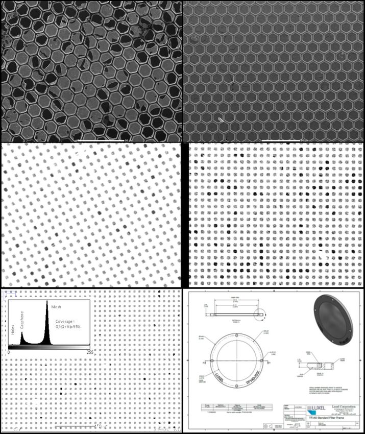
H. Todd Smith et al.: APL JANUS System Progress on Commercial Suborbital Launch Vehicles

low-cost strategy, the JANUS platform is being developed in         Processor, 200 MHz crystal oscillator, and a power-on reset
an iterative fashion with limited funding. As we fly missions,      circuit. This board contains 128 GB of flash memory, a UART,
we improve JANUS capabilities as needed and defined                 a FTDI USB controller, and a JTAG/SPI for test purposes, and
through flight testing.                                             it can store up to three software versions in 2 MB of onboard
     The current JANUS version (2.1) is a modular and               MRAM that can be selected at start up. All of the previously
stackable integration sub-payload that allows for expansion         mentioned instrument and spacecraft data interfaces can be
to support multiple experiments on Masten Space Systems,            found on this board as well.
Virgin Galactic, and Blue Origin sRLVs. For commercial                    The current JANUS platform is an example of its own
suborbital missions where the unit is returned, this payload        merits of the rapid iteration enabled by a fast flight cadence:
can be completely self-contained, consisting of a flight battery,   it is the third version of the JANUS platform, with its design
harnesses, low-voltage power supply (LVPS) electronic               iteratively improved through flight tests on sRLVs. This
board, and a processor board. The dimensions of JANUS               platform supports a three-phase strategy for the APL CSP.
2.1 are 19.6×5.7×15.2 cm with a mass of 1.4 kg (Figure 1).          We are currently completing Phase 1 with the development
The current JANUS 2.1 design includes: ±15 V, +5 V, +3.3 V          of the JANUS platform, establishing interfaces for multiple
and high-current +5 V power interfaces; 128 GB flash data           spacecraft, and assessing the applicability, limitations, and
storage; a high rate USB 2.0 interface for ground testing; and      suitability of the flight environment. So far, this phase has
many additional instrument interfaces (up to 24 customizable        involved six successful flight missions (on Blue Origin, Virgin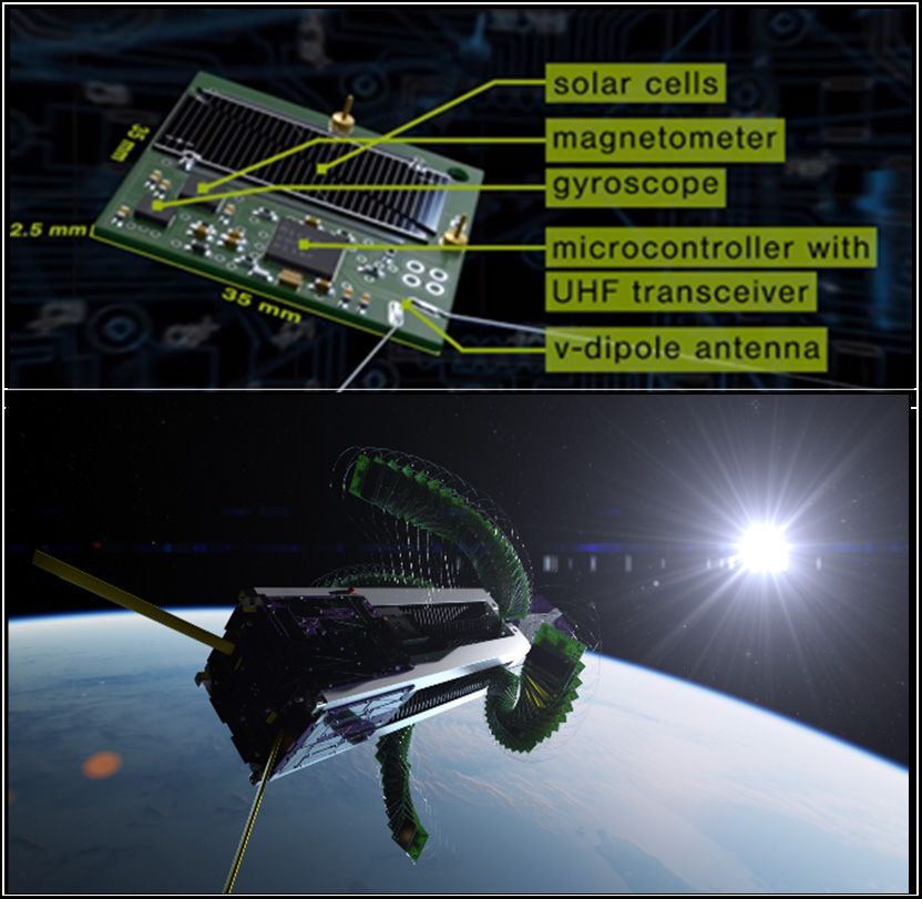
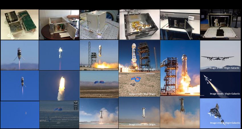
Gravitational and Space Research

Figure 1. (Top panel) JANUS 2.1 system. Top left: Double (left) and single (right) units with associated flight batteries and ground sup-
port system (middle). Top right: JANUS 2.1 dimensions. Bottom left: Low-voltage power supply electronics board. Bottom right: processor
electronics board. (Bottom panel). Images from the six completed JANUS mission (by column from left to right). Top row shows the JANUS
payload for each mission with flight images below each of these columns.

33
H. Todd Smith et al.: APL JANUS System Progress on Commercial Suborbital Launch Vehicles

Figure 2. 1st mission on the Masten Space Systems Xombie sRLV. Top: Magnetic field observations. Middle: Thermal observations of the
JANUS processor board. Bottom: Total acceleration observations.

                                                                                                                                  34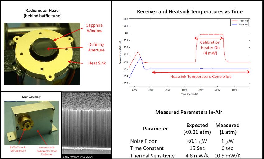
Gravitational and Space Research

safe return of the payload, would be improved based on in-          adding vector accelerometers, a vector IMU, and an improved
flight performance. Thus, we applied our intended iterative         thermal sensor. We upgraded the power supply to a Blue
approach to dramatically reduce the development cost of             Origin systems with significant flight heritage. Thus, even this
JANUS by supplementing ground testing with exposure to              modest flight activity noticeably improved the JANUS design
a more relevant flight environment. APL collaborated with           and validated the application of sRLVs in a low cost, rapid,
NASA to conduct a low-altitude “risk-reduction” flight while        and iterative development program.
awaiting higher-altitude operational flights that provide an
earlier opportunity to further test and improve this design.        2nd Mission: Risk-Reduction Flight for 1st APL-Funded
Although the actual launch of our 2nd mission (discussed            Payload (Blue Origin sRLV Escape Test)
later) happened slightly before this flight (resulting from early   Concurrently with the above NASA FOP flight activities, APL
stage launch date uncertainties), this risk-reduction mission       also conducted a self-funded flight test to assess JANUS
process was initiated earlier and considered our first mission.     acceleration-based trigger capabilities on the Blue Origin New
Additionally, our 2nd mission included design improvements          Shepard sRLV. This sRLV is also a VTVL rocket designed
based on the early stages of this mission.                          to carry up to six passengers to altitudes over 100 km. It is
      For this risk-reduction campaign, Masten Space Systems        approximately 18 m tall and composed of a pressurized crew
performed three activities with our payload at the Mojave Air       capsule (CC) with six large windows that integrates on top
and Spaceport in California on the Xodiac vertical takeoff          of a propulsion module (PM). The entire vehicle launches
vertical landing (VTVL) sRLV (Figure 2). The 3.7×1.8 m              using a single BE-3 liquid hydrogen/liquid oxygen (LH2/LOX)
unmanned vehicle is powered by a regeneratively cooled liquid       cryogenic engine producing ~100,000 lbf of thrust. The main
oxygen/isopropyl alcohol rocket engine and primarily used to        engine cuts off approximately 2.5 min after launch, and then
test Lunar and Martian landing technologies. However, this          the CC mechanically separates from the PM. Both components
sRLV can also perform low-altitude payload test flights. On         coast up to their respective apogees under momentum. After
October 24, 2016, our payload was integrated on the Xodiac          a few minutes of freefall, the PM autonomously returns to
launch vehicle and powered up for a static ground power test.       the landing pad approximately 1.5 km from the launch pad.
Then on October 27, 2016, our payload was integrated and            The CC also performs a soft landing under parachutes and
powered up for a tethered flight test. Finally, on November         retrorockets to a landing zone nominally within 8 km of the
2, 2016, our payload was integrated and powered up for              launch pad. The first New Shepard test flight successfully
the operational low-altitude free-flight test, which attained       returned the CC; however, the PM crashed. To date, two New
an altitude of ~0.5 km above ground level (AGL; Figure 2).          Shepard sRLVs have flown a combined 11 fully successful
Although these were very limited flights, the tests provided        flights.
a low-cost method of initial JANUS system flight testing that            Unfortunately, the launch date for our operational flight
allowed to dramatically improve the magnetometer design.            test slipped by over a year from October 2016 to 2017 because
      This test flight validated the pressure and thermal           our scheduled flight was reassigned as an “escape test” to
detections systems, and identified the critical need for            assess the vehicle capabilities to protect human life during a
accelerometer and magnetometer upgrades. Figure 2 shows             flight anomaly. Not only would this flight not follow a nominal
the magnetic field, total acceleration, and thermal data            flight profile, but there was an expectation that the propulsion
collected during the free-flight test. This risk-reduction flight   module may be damaged or destroyed during this test. This
was very successful as it indicated that the accelerometers         flight was designated “M6” by Blue Origin (referring to it as the
and magnetometers were not sufficient to meet mission               6th launch of the New Shepard). We took advantage of this
requirements. It is possible that several of these needs            situation to conduct a risk-reduction test of our own on this
for improvement would have been missed with ground                  flight while awaiting our nominal operational flight in 2017. For
qualification, because isolated test environments only test         this flight (and all subsequent Blue Origin missions so far),
for known conditions rather than comprehensively including          our payload was mounted inside of a 40.6 × 33.0 × 25.3 cm
all flight conditions. This flight was also successful in testing   enclosed payload locker integrated into one of six payload
autonomous, remote flight operations, in which it identified        “stack” locations inside of the pressurized CC. Each stack is
several critical issues that were corrected. Based on these         capable of accommodating up to six single payload lockers.
results, we dramatically improved the payload design of                  On October 5, 2016 (Figure 3), JANUS flew successfully
JANUS 2.0, helping improve the chances of success during            on the Blue Origin New Shepard launch vehicle from the West
an operational mission. In addition to making the payload           Texas Launch Site. Although this flight was not designed to
smaller (the new JANUS version was reduced to 21% of                reach maximum suborbital altitude, it involved a flight test
the volume and 28% of the mass of JANUS 1.0) and more               of the escape motors that subjected our payload to much
robust, we integrated a much better magnetometer as well as         greater launch and vibrational loads than nominal conditions

35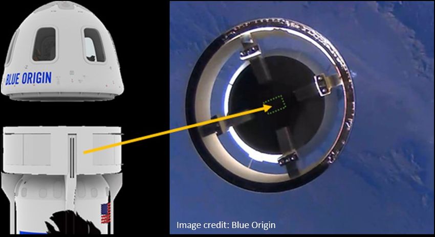
H. Todd Smith et al.: APL JANUS System Progress on Commercial Suborbital Launch Vehicles

Figure 3. 2nd sRLV mission on the Blue Origin New Shepard CC escape motor test. Left column: Acceleration (g) observations (y-axis verti-
cal in CC, x and z axes orthogonal to y-axis). Right column: Rotational (deg/s) observations (y-axis vertical in CC, x and z axes orthogonal to
y-axis).

(by greater than a factor of 3) and reduced our ground testing           demonstrating the value of low cost, iterative development
requirements. Approximately 45 s after launch, the escape                enabled by sRLVs.
motors of the New Shepard CC successfully separated                           The JANUS payload performed successfully, without any
it from the PM and safely returned to the landing area.                  anomalies and exceeded all testing requirements under much
Interestingly, the PM also survived the escape test, continued           more extreme flight conditions than those anticipated during
to a nominal apogee and safely returned to the landing                   operational flight. Figure 3 also shows the acceleration and
pad. This risk-reduction flight for JANUS comprehensively                rotation observations collected by JANUS during this flight,
replaced our standard suite of expensive and time-consuming              which were accurately captured across all phases of the flight.
environmental testing required for the next launch, thus                 These data show that even under the most extreme flight

                                                                                                                                          36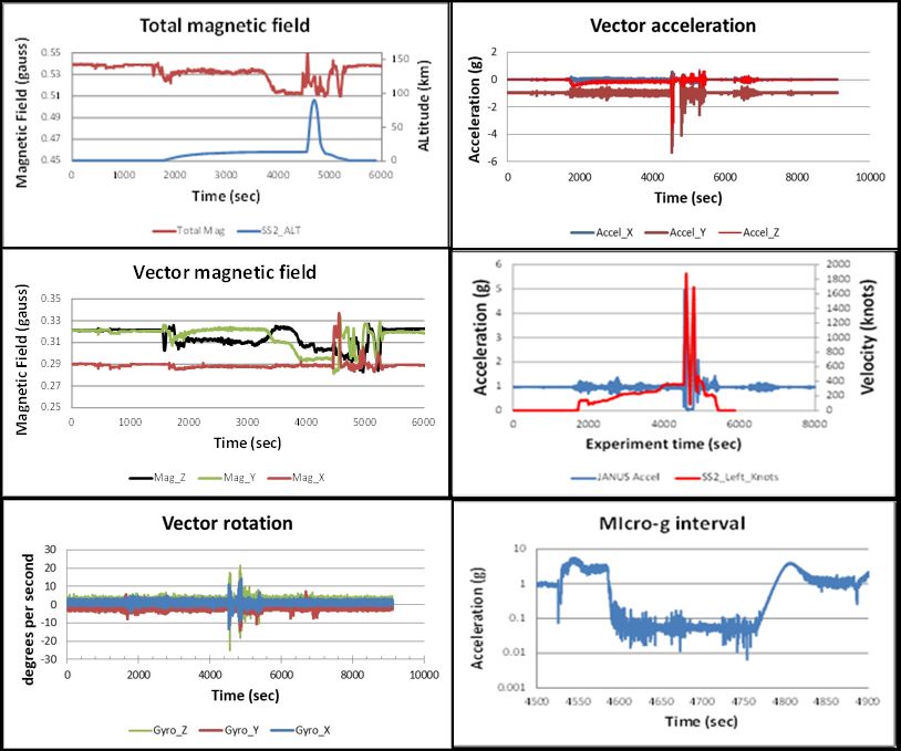
Gravitational and Space Research

Figure 4. 3rd sRLV mission on the Blue Origin New Shepard sRLV. Left: Acceleration (g) observations (y-axis vertical in CC, x and z axes
orthogonal to y). Right: Rotational (deg/s) observations (y-axis vertical in CC, x and z axes orthogonal to y-axis).

conditions, this vehicle presents a relatively gentle launch           recovered successfully within two hours of landing; data
environment with a very soft landing. This flight activity also        analysis at APL showed all JANUS sensors and functions
allowed the APL CSP to greatly improve its flight operations           operated successfully, with all 35 acceleration-based triggers
procedures, dramatically reducing the risk for future                  flawlessly tracking all phases of flight. Figure 4 shows the
operational flights. Thus, these results help demonstrate our          acceleration and rotation data collected during this flight with
assertion that sRLVs can be essentially utilized as a low-cost         key flight events annotated. These data were collected at a
laboratory in near space once regular and frequent flight              high time resolution of 4 kHz, once again demonstrating the
cadences are established.                                              benign flight environment and very soft CC landing. Based on
                                                                       this flight, we were able to verify flight readiness for our first
3rd Mission: First Operational Flight Test of JANUS (Blue              NASA FOP-funded operational flight and make minor design
Origin sRLV)                                                           improvements to JANUS 2.1.
The next JANUS suborbital flight test was the operational
APL-funded flight related to the previous risk-reduction flight,       4th Mission: First Magnetic Field Experiment (Blue Origin
and it was the first to attain nominal altitude for the Blue Origin    sRLV High-Altitude Escape Test)
New Shepard. This flight offered APL its first opportunity to          Following the above launch activities, APL was able to
analyze nominal flight conditions of the New Shepard vehicle           conduct its first NASA STMD FOP- funded operational
to assess its applicability for future research and engineering        mission. The flight objective of the proposed experiment was
flights.                                                               to characterize the ambient electromagnetic field environment
     Blue Origin’s New Shepard “M7” mission was launched               in the CC to assess external and internally generated fields.
on December 12, 2017, from the West Texas Launch Site                  Additionally, we improved the payload design of JANUS 2.1 by
(Figure 4). In addition to improving flight heritage for the           integrating the above fluxgate magnetometer and upgrading
upgraded JANUS 2.0 design and characterizing the ambient               vehicle physical and electrical interfaces. This flight test
payload environment, we also conducted 35 acceleration-                (“P6” referring to the 6th flight containing payloads) occurred
based experiments to test JANUS’s ability to identify all              during the July 18, 2018, “high-altitude escape test” of the
changes in the flight environment correctly. The CC reached            Blue Origin New Shepard launch vehicle at the West Texas
an altitude of 99.3 km AGL during this flight with a total flight      Launch Site (Figure 5). This high-altitude escape test involved
time of 603 s. The capsule landed less than 1.5 km from                ignition of the CC escape motors after separation from the
the launch pad, with a maximum descent velocity of Mach                Propulsion Module. This activity resulted in the CC attaining
2.94. The PM, after reaching a maximum descent velocity                a much higher than nominal altitude of 118.8 km AGL, thus
(Mach 3.74), successfully reignited its engines and landed             allowing us to make observations at altitudes higher than
safely on the landing pad. JANUS 2.0 (Figure 4) performed              those attained during normal flight.
successfully throughout the entire flight and continued to                  JANUS 2.1 performed very well and we successfully
operate in low-power mode after landing. The payload was               measured the Earth’s magnetic field from inside of the CC

37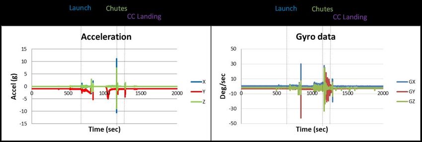
H. Todd Smith et al.: APL JANUS System Progress on Commercial Suborbital Launch Vehicles

Figure 5. 4th mission on the Blue Origin New Shepard sRLV. Left middle: Magnetic field observations by axis. y-axis vertical in CC, x and
z axes orthogonal to y-axis. Bottom middle: Rotation (deg/s) observations. Top right: Micro-gravity period analysis (g). Right middle: Total
magnetic field observations (gauss). Bottom right: Acceleration (g) observations by axis.

(Figure 5). The magnetometer data show the total and axial               with the exception of relatively minor perturbations (on the order
magnetic fields observed during the flight test with key events          of
Gravitational and Space Research
Figure 6. 5th sRLV mission on the Blue Origin New Shepard vehicle. Top left: Total magnetic field (gauss) observations. Bottom left: Axial
magnetic field (gauss) observations. Top right: Axial acceleration (g) observations. Bottom right: Low-gravity field (g) observations. y-axis
vertical in CC, x and z axes orthogonal to y.
to assess the quality of the micro-gravity portion of the flight. JANUS 2.1 characterized the flight environment with a
Figure 5 also shows the measured microgravity environment. successful measurement of the Earth’s magnetic field from
Once the acceleration stabilized at or below 0.05 g, we inside of the CC, and we were able to observe perturbations
record an average 0.043±0.002 g for a duration of 182.03 s to this field as a result of specific spacecraft activities and
(this variation is likely a combination of thruster firings and maneuvers (Figure 6). However, some small perturbations
measurement noise). JANUS 2.1 performed successfully were unexpectedly different from our P6 observations. While
during this flight and exceeded all test requirements during a some differences can be explained by the escape motor
higher than nominal flight profile resulting from the additional activities on P6, the sources of other differences have not
escape motor acceleration. been fully identified but are likely the result of other payload
or vehicle instrument activity. This may indicate that for
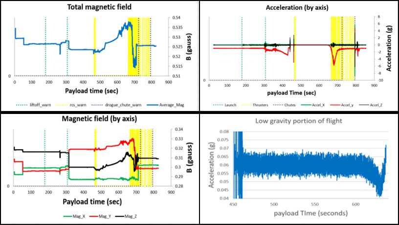
5th Mission: Second Magnetic Field Experiment (Blue experiments sensitive to EMI, a pre-flight test activity with
Origin sRLVN Flight) all payloads operating with magnetometer observations may
Following the previous flight test, APL conducted its first be beneficial. Another remediation step may be to populate
operational, nominal flight profile test of the JANUS system certain flights with only low EMI payloads.
(funded by NASA FOP). The goal of this flight and the JANUS Figure 6 shows our magnetometer data with total and
2.1 configuration were similar to the previous flight; however, axial magnetic fields observed during the flight test annotated
this flight followed the nominal profile expected during future with key events (launch, reaction control thruster events,
flights. This flight test occurred on a Blue Origin New Shepard and parachute deployment) in the figure. Prior to launch,
P7 launch out of the West Texas Launch Facility on January we observed the unperturbed Earth’s magnetic field from
23, 2019. The flight proceeded successfully, reaching an inside the CC (and inside a payload locker), which was
altitude of 107 km with safe landing of the CC and PM (Figure stable (0.526±0.002 gauss). These figures show that after
6). This was our first opportunity to examine magnetic fields launch, the magnetic field slightly decreases as expected
and microgravity inside of the New Shepard CC during a from the increase in altitude. Figure 6 can be compared with
nominal flight profile. the magnetic field profile we observed during P6 (Figure 5).
39H. Todd Smith et al.: APL JANUS System Progress on Commercial Suborbital Launch Vehicles
The basic profiles are similar, but there are some unexpected The vehicle is a suborbital spaceplane that is air launched
differences. As expected, the CC experienced noticeable from the dual fuselage White Knight Two aircraft at an altitude
immediate EMI during the P6 escape motor test and then of approximately 50,000 feet. Once released, SpaceShipTwo
dropped off (from ~500 s until ~700 s), verified by the lack of is powered by a single hybrid rocket engine up to apogee. It
this feature in the P7 data. Interestingly, during both flights, then applies a feathered wing reentry system and lands on
the total observed magnetic field steadily increases around a standard runway. Virgin Galactic was in an earlier stage
apogee, then dramatically drops off, and recovers to what of flight testing than Blue Origin and so this flight was not
appears to be the ambient Earth’s magnetic field. Even intended to reach nominal altitudes. However, this provided
more curious is that this feature appears to occur after chute our first opportunity to flight test JANUS on SpaceShipTwo
deployment during P6 but before chute deployment (after to analyze flight conditions for this completely different type
apogee) on P7. Although we have not identified the source, of sRLV.
we hypothesize this event is EMI-related. Additionally, This flight test occurred at the Mojave Air and Space Port
during P6, after chute deployment, there are relatively large in Mojave, California, on February 22, 2019 (Figure 7). VSS
magnetic field oscillations that do not appear during P7. This Unity performed successfully reaching an altitude of 89.9 km
feature is likely caused by EMI from other payloads as it AGL and a top speed of Mach 3.0. In addition to carrying
seems unlikely that that the high-altitude escape test flight JANUS (as well as other payloads), this was the first flight
would cause EMI during this phase. These results illustrate with a human test passenger. JANUS 2.1 payload performed
that electromagnetic interference occurs during different flight very well and we successfully recorded environmental data
phases and must be accounted for when either measuring during all aspects of the test flight.
the Earth’s magnetic field or conducting experiments that Figure 7 shows our vector acceleration observations as
are sensitive to EMI. We intend to continue analyzing these well as the total magnetic field compared to vehicle altitude,
data with respect to axial orientation, including in the context with data recorded at a 1.67 kHz cadence. Such a high rate
of and combined with future flight data, to more accurately measures short impulses and may give the appearance of
determine the sources of EMI during flight. Additionally, in the higher accelerations than would actually be perceived by
future we will mount JANUS externally on the launch vehicle, flight participants as each observed value only represents
and we can then compare observations to determine the a 6´10-4 s time period. Additionally, payload integration on
absolute impact of the CC on magnetic field observations as this early stage flight is still under development, so APL
well as the ability to measure external magnetic fields. This was required to develop a custom payload container that
work can eventually lead to an assessment of spacecraft integrated into the current VSS Unity payload locker using
charging and the measures required to make accurate custom struts (Figure 7). These struts were an expedient
external observations. way of integrating our payload but may have impacted the
Figure 6 also shows our acceleration observations for the acceleration profile on the payload. We intend to examine
payload x-, y-, and z-axis with key events (launch, RCS firings, this design and develop a more robust integration system
parachute deployment) annotated on the figure. The data show for future flights if needed. However, these data accurately
the load experienced during launch as well as reentry, which is represent the current payload environmental conditions and
very similar to the P6 flight. Additionally, we were able to again constitute JANUS’s first observations of a SpaceShipTwo
assess the microgravity environment. Once the acceleration flight profile. After White Knight 2 takeoff (at ~1800 s),
is stabilized at or below 0.07 g, JANUS recorded an average our payload experienced a low-level acceleration until the
0.059±0.005 g for 185.99 s. Interestingly, the previous escape peak acceleration after the SpaceShipTwo rocket ignition
test flight (P6) achieved slightly lower and more stable gravity (at ~4500 s), followed by the microgravity period. Once
than this nominal flight. This is likely because the CC attained the acceleration stabilized at or below 0.1 g, we recorded
a higher altitude into a slightly more rarified region during the an average 0.057±0.015 g for 162.03 s (Figure 7). We
high-altitude escape test. anticipate that this environment may become more stable as
the spacecraft achieves more nominal, higher altitudes. After
6th Mission: First Virgin Galactic sRLV Magnetic Field this time period, acceleration increased dramatically during
Experiment initial descent and then reduced until it spiked again during
Our next JANUS flight test was similar to the previous one landing. We also observed minor accelerations during taxi
with the exception that it was flown on the Virgin Galactic back to the hanger. Figure 7 also shows total acceleration
SpaceShipTwo (VSS Unity), which is designed to carry two compared to velocity profiles. Additionally, JANUS’s Inertial
pilots and six passengers up to altitudes of ~110 km. This Measurement Unit showed minor oscillatory rotations, likely
sRLV design is radically different from the Blue Origin New introduced by our custom strut interface to the payload
Shepard, and it will likely be suitable for different applications. locker.
40Gravitational and Space Research
Figure 7. 6th sRLV mission on the Virgin Galactic SpaceShipTwo. Top left: Total magnetic field (gauss) observations compared to vehicle
altitude (km). Middle left: Vector magnetic field (gauss) observations. Bottom left: Vector rotation (deg/s) observations. Top right: Vector
acceleration (g) observations. Middle right: Total acceleration (g) compared to vehicle velocity (knots). Bottom right: Low-gravity field (g)
observations. y-axis vertical in CC, x and z axes orthogonal to y axis.
Figure 7 shows magnetometer observations from the powered ascent, the microgravity phase, and initial descent.
flight, as well. These data show the total and axial magnetic We need to work further with Virgin Galactic to attempt
fields observed during the flight test relative to altitude to isolate the sources of EMI. Of note, the payload x-axis
and acceleration. Prior to takeoff, we adequately observed magnetic field is very stable with several sharp peaks after
the Earth’s magnetic field from inside the spacecraft separation, likely indicating spacecraft EMI (this direction is
(and inside a payload locker) and was very stable at an in the vertical plane of the vehicle). It is possible that some
expected value, measured at 0.5391±0.0005 gauss. This observed EMI is actually from other payloads rather the
reading was the same before and after JANUS was placed spacecraft itself. Therefore, as with our Blue Origin flights,
inside the spacecraft, thus indicating that vehicle itself is we will gain much more insight by comparing these results
not significantly interfering with the observations. However, with future flights.
there is noticeable EMI during takeoff as well as during
41H. Todd Smith et al.: APL JANUS System Progress on Commercial Suborbital Launch Vehicles
JHU/APL SCHEDULED FLIGHT EXPERIMENTS maintaining our atmosphere and causing significant impact
such as high-altitude lighting, we have made limited progress
NASA FOP has selected and funded multiple future APL sRLV in quantifying their variability, either spatially or temporally.
missions that will transition our program from flight environment Remarkably, we appear to have more measurements of
assessment and suitability (Phase 1) to technology negative ions in the ionosphere of Saturn’s moon Titan from
demonstrations and scientific research (Phase 2). The APL the NASA Cassini mission than we do of Earth’s ionosphere
CSP is currently scheduled to fly JANUS on the next Virgin (Rymer et al., 2009; Smith and Rymer, 2014).
Galactic SpaceShipTwo flight to analyze the acceleration and There are also numerous examples of benefits for NASA
magnetic field environments for a nominal flight profile, which and commercial end users for technology development
should provide insight into the suitability of this sRLV for various enabled by sRLV missions. In these cases, new technologies
applications. JANUS is also manifested to fly on the next Blue or instrument designs can be rapidly developed or advanced
Origin New Shepard launch to establish a direct connection to market with flight heritage through external access on low
between our GPS receiver and the spacecraft GPS antenna. cost, frequent launches. The below follow-on missions help
The new capability will combine with our IMU to provide for illustrate some such examples. There are many more infusion
much more accurate inflight position and velocity information possibilities for end users enabled by external access than
as well as the possible measurement of atmospheric Total these examples below, but these help to illustrate the far
Electron Content (TEC) on all future flights (Sukkarieh et al., reaching applications, with many more certainly emerging as
1999; Dyrud et al., 2007; Copper et al., 2019) and crosses external environment access capability is established.
over into the CSP Phase 2. Such observations could provide However, establishing external access capability is very
unique results as these data have never been available at challenging as it is difficult to integrate a payload outside of
suborbital altitudes at the frequency and resolution enabled the vehicle without increasing risk related to the capsule/
by multiple JANUS flights. With successful completion of fuselage structure and aerodynamics, and these sRLVs are
these flight tests, the JANUS platform will be ready to support designed primarily as commercial human transports rather
operational research and engineering missions on both Blue than conveyors of scientific payloads. Fortunately, after
Origin and Virgin Galactic sRLVs. Additionally, the above considerable collaboration with Blue Origin, we were able to
successfully completed missions have validated the ease identify a location on top of the PM that could accommodate
at which the JANUS system can inexpensively and rapidly an external payload which is extremely well suited for
support multiple experiments. Below, we briefly describe the both Blue Origin and APL (Figure 8). First, the risk to the
NASA FOP-selected sRLV missions that JANUS is scheduled CC is minimized as the payload will be placed on the PM.
to fly from 2021 to 2023. Additionally, this location places external payloads in vehicle
ram facing direction during ascent, which is ideal for sampling
Establishing Access to the External Spacecraft the external environment and collecting particles. This is also
Environment a good location for observing upward. Since the maximum PM
In these previous missions, the JANUS 2.1 has flown inside of altitude is close to that attained by the CC, little performance
the pressurized New Shepard CC or SpaceShipTwo fuselage. is lost by this payload relocation. Additionally, during initial
However, many scientific payloads require direct access to descent, this payload location will be in the anti-ram orientation,
space. Thus, the first mission of the APL CSP Phase 2 involves which may be better suited for payload deployments (as our
establishing payload access to the external spacecraft ChipSat mission discussed later).
environment. In situ measurements at the altitude range 60– Our next scheduled JANUS mission will involve flying
120 km are so sparse because it is too high for conventional on top of the New Shepard PM to establish an interface
aircraft and balloons yet too low for orbiting satellites. To date, for external payloads and to analyze the flight environment
only sparse and infrequent rounding rocket observations exist from this location. After successful completion of this mission
for this region. For example, Barucci et al. (2011) outline the (tentatively scheduled for 3rd quarter of 2021), APL will
great need to characterize the billions of meteoroids that enter begin the operational phase (Phase 2) of its CSP involving
Earth’s atmosphere each day (Ceplecha et al., 1998) and research, technology demonstration, and instrument testing
assess their impact on our atmosphere. External environment and validation.
access provides the opportunity to directly sample meteoric-
based aerosols greater than 10,000 cm-3 near 100 km (Hunten Technology Demonstration of Vertically Aligned Carbon
et al., 1980; Cziczo et al., 2001). Nanotubes for Radiometers
Another scientific application involves studying the complex The APL CSP will conduct its first technology demonstration
and variable ion chemistry in Earth’s upper atmosphere. flight test once the above external environment access
Despite charged particles in this region being critical for interface becomes operational. The goal of this test is to
42Gravitational and Space Research
Figure 8. Payload location on top of the Blue Origin New Shepard PM for external space environment access.
demonstrate a vertically aligned carbon nanotubes (VACNT)- stray light suppressors, emitters for thermal management,
based radiometer technology on a commercial sRLV. The sources of electrical generation and transmission, and super-
results of this flight demonstration would raise the TRL, light structures. External environment testing and validation
validating their proposed use in future NASA and operational on sRLVs would provide a cost-effective, rapid method of
Earth science missions. verifying flight survivability and thermal response in a near
We intend to use sRLVs as a low cost, rapid platform space relevant environment.
for improving VACNT radiometers based on the lessons We are motivated to pursue this particular application
learned from the RAVEN mission. VACNT-based bolometer of VACNTs because two advancements are needed to
radiometers can provide instrument improvements needed measure the absolute radiation imbalance thought to drive
to make Earth- and Sun-observing radiometers sufficiently climate change: a minimum of 20˚–30˚ wide field of view
accurate and low cost to measure Earth’s absolute energy radiometers encircling the globe and affordable-highly
balance/imbalance for the first time. This is precisely the accurate radiometers. Our VACNT radiometer design
measurement that is needed to resolve the climate change (Figure 9) is based on the one recently flown on the NASA
debate and enable vastly superior predictions of future ETSO RAVEN CubeSat technology demonstration mission
change. Thus, our suborbital testing mission will provide (Swartz et al., 2019). The sensor weighs 145 grams with
a low-cost opportunity to prepare such detectors for future a diameter of 2 inches and a height of 2.125 inches. It is
operational missions. constructed primarily of Aluminum 6061 and Copper OPHC
VACNTs are very promising material development in with a sapphire window. The VACNTs were grown on a
space technology over the last decade (Figure 9). They 1 cm2 wafer affixed to a 4% Ag substrate. This sensor uses
are cylindrical carbon structures aligned perpendicular to +5 V, 15 uF, and 80 mA (analog) and +3.3 V, 15 uF, and max
a substrate, and they are considered the blackest known 35 mA (digital) connections, which are easily provided by
substance to humankind (Yang et al., 2008; Mizunoa et JANUS. The field of view is 127 steradians. The radiometers
al., 2009). Additionally, VACNTs do not outgas or cause are designed to cover the flux range from direct solar
contamination, are mechanically robust, and have an measurements (1361 W m−2) down to those encountered
extremely large thermal conductivity (Sample et al., 2004; Xu viewing the Earth (100–750 W m−2) with a precision of
and Fisher, 2006; Cola et al., 2007). Because of their uniqueH. Todd Smith et al.: APL JANUS System Progress on Commercial Suborbital Launch Vehicles
Figure 9. Top left: VACNT radiometer head. Bottom left: Radiometer payload assembly. Bottom center: Growth from rectangular patterned
catalyst region of VACNT substrate. Right: Summary of radiometer test results.
Technology Demonstration of Graphene Foils to grow graphene test foils (funded for this project through
APL’s second Phase 2 mission is funded by NSA FOP and the NASA SBIR program), and we conducted ground tests of
involves a technology demonstration of graphene foils for their charged particle transmission factors as well as scanning
integration into particle detectors for observations of planetary electron microscope (SEM) imaging to examine microscopic
atmospheres, including Earth’s. Graphene is a material with structure (Figure 10). Remapping showed the graphene
a number of unique qualities, including low permeability coverage to be 89% to 95% after transport, SEM cycles, and
and high strength combined with low mass, but as a particle Ar+ bombardment compared, with 88% to 96% as-made.
detector membrane, this technology currently resides at TRL The foils are contained in individual enclosures (Figure
3. Through this proposed technology demonstration we intend 10) that will be integrated on JANUS, which will be mounted
to raise the TRL of graphene membranes to seven. externally on the Blue Origin New Shepard PM interface
Many particle detectors use traditional carbon foils in the for a flight test tentatively in late 2021. JANUS will provide
entrance aperture to help identify incoming particles, as well environmental monitoring while the foils experience the full
as to select the type of particles allowed to enter (Hamilton range of spaceflight stresses.
et al., 1990; Young et al., 1991). We are highly motivated to In preparation for this flight demonstration, we researched
apply graphene membranes on particle detectors because and developed a method of fabricating graphene membranes.
they provide noticeably reduced foil mass and decreased The process produced grid-supported single-layer graphene
power requirements over traditional carbon foils (Graf et al. (SLG) membranes on nanohole arrays (with hole diameters in
2007; Koenig et al. 2011, 2012). These advantages, when 150–400 nm range) with hole coverage of 99%. The nanohole
combined with anticipated performance improvements, could arrays, with hole diameters in 150–400 nm range and an
enable critical scientific measurements where mission cost, open fraction ~8%, were also highly efficient Ly-a (122 nm)
performance, or TRL limited such graphene application. For blockers, with a demonstrated transmission of ~0.2%. We
this experiment, we worked closely with Luxel Corporation also developed a method for attaching SLG to Ni without
44Gravitational and Space Research Figure 10. Top: Single-layer graphene attached to lithographically patterned Al 3 micron wide mesh (Left panel: A bad region with substantial cell breakage. Right panel: A good region with essentially all cells intact). Middle left: Single-layer graphene #G13 on 2000 lpi Ni mesh as- made. Middle right: Sample after 90 days, two cross-country FEDEX trips, 3 cycles into an SEM, and a few days of 10 keV Ar+ ion bombard- ment. Bottom left: Detection of single-layer graphene #G15 using SEM (inset shows gray levels associated with the mesh, the graphene- covered cells, and holes). Bottom right: Foil test flight enclosure. 45
H. Todd Smith et al.: APL JANUS System Progress on Commercial Suborbital Launch Vehicles

Figure 11. Top: Schematic of 200 g ChipSat. Bottom: TRL 7 ChipSat Deployer on a 1U CubeSat to be used during the suborbital flight test
(Image Courtesy of Ben Bishop).

adhesive and bilayer graphene (BLG) membranes with >95%               pinhole, while the other is left open. The motion stage slews
coverage on Ni mesh, achieving areas up to 10 cm2 on the 8            the collimator with and without the graphene sample in and
micron pitch and 40% open area hexagonal mesh (Zeiger et              out of the beam. The beam imager is made by Quantar and
al., 2019)                                                            consists of a 70 mm2 open face microchannel plate (MCP). On
     Once these graphene foils were fabricated, we conducted          the backside of the MCP is a position-encoding anode. During
a simple experiment to verify the integrity of the samples. In a      the experiment the vacuum pressure was 1´10−7 torr. The test
vacuum system, we set up a particle beam experiment with an           verifies graphene coverage of the mesh support. Based on
ion beam gun, pinhole collimators attached to a motion stage,         the results from test foils, we fabricated two sets of two flight
and a Quantar beam imager. The ion beam composition is an             test foils (four in total). One set will be exposed to atmosphere
admixture of protons, nitrogen, and other air-like constituents       and the other will be held in vacuum during launch.
and can span an energy range from hundreds of eV to 10 keV.                We intend to measure charged particle transmission
The pinhole collimator system consists of a rectangular               through the exposed foils into individual Faraday Cups (FC)
aluminum plate with two pinholes approximately ~1 mm                  during flight. We will then retrieve these foils after flight and
in diameter at a distance of 88 mm upstream of the beam               reproduce the previous ground tests to examine performance
imager. Graphene samples to be tested are mounted over one            and possible damage caused by flight. This will help provide

                                                                                                                                     46
Gravitational and Space Research
insight into the suitability of these foils for future particle appreciable lateral acceleration, and they will descend along
detection instruments. with the PM. JANUS will also record the usual environmental
observations to combine with the ChipSat individual data.
Suborbital Flight Testing of Chip-Scale Satellites The ChipSats’ low ballistic coefficient may disperse them up
The next NASA FOP-funded JANUS-supported flight test is to several miles from the launch site, yielding valuable, first-
a technology demonstration of chip-scale satellite (ChipSat) ever data of this type on upper-atmospheric winds and other
deployment from a commercial reusable launch vehicle. More environmental phenomena. The ChipSats continually transmit
specially, our project will conduct a flight test of the JANUS- their GPS-derived position, so they can be located and
ChipSat payload on a Blue Origin New Shepard launch vehicle collected after they land. The results from this flight test will
to raise TRL for future Earth and lunar/planetary missions. A provide critical information on the survivability and operation
ChipSat is a very small, open-source, 2–4 gram, free-flying of these ChipSats for suborbital applications and help raise
TRL 7 (4 gram version) spacecraft with actuators, solar panels, TRL for orbital (and beyond) applications.
sensors, processing, communications, and structure, as well
as power suitable for a wide variety of small-scale payloads Suborbital Flight Testing of Charged Particle Technology
(Figure 11). Our goal is to validate operational capabilities as NASA FOP has also selected an APL mission to conduct a
well as assess the reentry survival rate of ChipSats that will be suborbital flight test of a charged particle instrument being
deployed from the external payload location on top of the Blue developed for the Europa Clipper instrument. The test also
Origin New Shepard Propulsion Module. facilitates establishment of the first external in situ particle
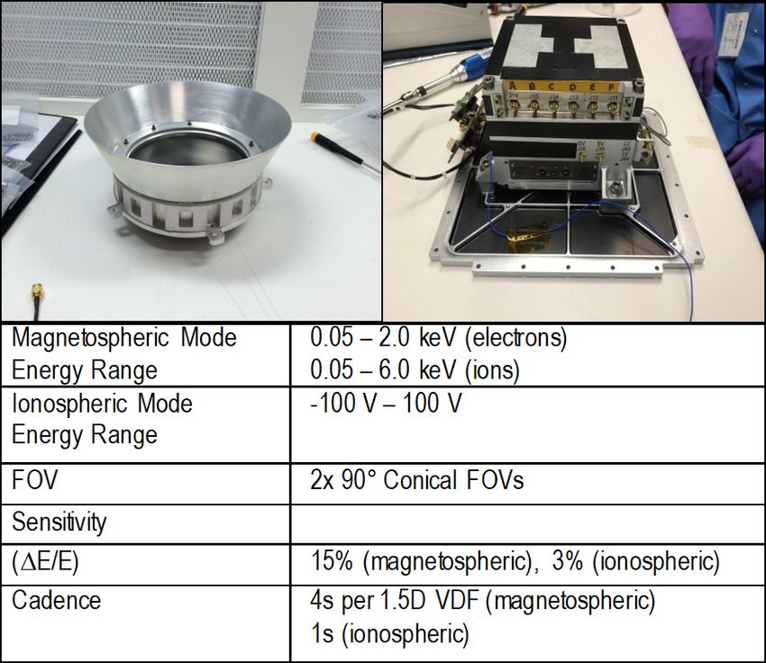
These “ChipSat” (sometimes referred to as observations on the Blue Origin New Shepard sRLV. A goal
femtosatellites on the order of less than 100 g) can be of this mission is to develop a low cost, reliable method of
produced in large quantities at very low cost, which offers making in situ particle observations at suborbital between
the possibility of deploying hundreds or thousands of such 60and 120 km. This region, while extremely important for
satellites to provide coincident coverage on spatial scales understanding our atmosphere, still contains many mysteries
previously unimagined (Streetman et al., 2015; Gilster, 2017; because it has been difficult to access. It is not easily
Howard, 2017). Development and testing of this new class of accessible due to logistical constraints, i.e., too high for
satellites has only recently emerged, and key open questions conventional aircraft and balloons, too low for orbiting satellites.
remain about their functionality as a network and their ability However, it is an important region of Earth’s atmosphere
to return samples and data through the atmosphere without encapsulating two important atmospheric boundaries: the
appreciable signal degradation. Thus, the TRL of these “mesopause” and “turbopause”—these encompass the
devices needs to be improved before they can be applied altitudes where atmospheric temperature is lowest and the
operationally for missions that exploit these capabilities. chemical constituents cease to be well mixed—both critical
A 2011–2014 experiment on the International Space in determining the Earth’s temperature and chemical profile.
Station (MISSE-8) validated the architecture and verified Ion chemistry at the Earth is complex and variable but we
the performance of key components in LEO. Next, the have made limited progress in quantifying its variability, either
KickSat-1 spacecraft (Manchester et al., 2013) was launched spatially or temporally (Arnold et al., 1971) at the proposed
in 2014 with 104 ChipSats; however, the spacecraft did not suborbital altitudes.
successfully deploy them. More recently, members of our This flight test of our payload will enable a better
team participated in the successful KickSat-2 mission in understanding of this critical transition region of our
March 2019, which achieved successful deployment of 105 atmosphere. This involves application of a suborbital variation
four gram ChipSats. of the Plasma Instrument for Magnetic Sounding (PIMS)
For this mission, we will deploy 100 improved (2 gram) shown in Figure 12. PIMS, scheduled to be flown on the
ChipSats with GPS and networking capability, not only to test NASA Europa Clipper mission, is primarily a FC with a 90°
operational measurement capabilities but also to conduct the FOV measuring the 1.5-dimensional velocity distribution
first ever test of survival capabilities under suborbital reentry. function of ions and electrons. This FC measures the current
We will then use satellite GPS signals to recover them from produced on metal collector plates by charged particles
the landing site and analyze their survivability rate. We will with sufficient energy per charge (E/q) to pass through a
deploy the ChipSats just after apogee of the suborbital modulated retarding grid placed at variable (AC) high voltage
flight, each capable of reporting attitude and position (GPS) (HV). Figure 12 also shows the characteristics of this sensor
data along with temperature, pressure, and magnetic-field (note for the proposed flight test, we only require a test of the
measurements. They will be released through the flight- low energy, or “ionospheric,” mode).
heritage deployer design triggered by JANUS, which is roughly The key focus of this flight test will be integration with the
the size of a 3U CubeSat (Figure 11), but they will not gain JANUS system on the external mounting location on the New
47H. Todd Smith et al.: APL JANUS System Progress on Commercial Suborbital Launch Vehicles
Figure 12. Top left: PIMS Faraday Cup sensor. Top right: PIMS electronics assembly/bank. Bottom: PIMS operational constraints.
Shepard PM. We will conduct measurements of electrons and operational technology demonstration and research missions.
negative ions during all phases of the flight. The intent will be These activities will not only develop novel applications for
to enable these observation during all subsequent flights of these new vehicles but also allow for support of much larger
JANUS. Such observations will be the first analysis of charged missions on commercial orbital launch systems as well as
particles in a specific suborbital region over many different commercial lunar landers.
time periods affording us unprecedented temporal and spatial
insight in this atmospheric region.
ACKNOWLEDGMENTS
SUMMARY
This work is supported by the NASA Science Technology
Mission Development Flight Opportunities Program and Game
While originally targeting space tourism, commercial reusable Changing Opportunities in Technology Development Program
suborbital launch vehicles offer game-changing capabilities as well as the Johns Hopkins Applied Physics Laboratory
for scientific research as well as instrument development and Internal Research and Development Program. The graphene
technology demonstration. Key aspects of these revolutionary development was funded at Luxel Corporation through NASA
spacecraft include dramatic reduction in cost over existing SBIR NNX17CG14C.
suborbital platforms and a guaranteed safe return of payload
on launch day. The JHU APL has established a CSP to rapidly
REFERENCES
exploit these new vehicles. The core of this program is the
JANUS system that provides common payload capabilities
for power delivery, data logging, event triggering, and Arnold F, Kissel J, Krankowsky D, Wieder H, Zähringer J (1971)
environmental monitoring, eliminating the need to develop an Negative ions in the lower ionosphere: a mass-spectrometric
entire new payload for each flight. JANUS has already flown measurement. Journal of Atmospheric and Solar-Terrestrial
six successively more complex flight tests of this system on Physics 33(8), 1169–1170.
Masten Space Systems, Blue Origin, and Virgin Galactic Arnold SP, Smith HT (2013) Suborbital flights for space science. In
vehicles (funded by NASA and APL) to develop the JANUS AIAA SPACE 2013 conference and exposition, September 10–12,
system and characterize vehicle environments. All data is 2013, San Diego, CA, doi: 10.2514/6.2013-5350.
available upon request. APL is now preparing to conduct five
48You can also read