Design and integration of 1D and 2D diffractive beam splitters (multi-spot) into optical systems in sequential and non-sequential mode of - ZEMAX ...
←
→
Page content transcription
If your browser does not render page correctly, please read the page content below
2021

Design and integration of 1D
and 2D diffractive beam
splitters (multi-spot) into
optical systems in sequential
and non-sequential mode of
ZEMAX™
TUTORIAL
HOLO/OR
Contents

1. Introduction……………………………………………………………………………………………………….2
 1.1. Preliminary reading………………………………………………………………………………………………………………………. ……..2
 1.2. Definition of Diffraction Grating Surface in ZEMAX™ …………………………………………………………………………….2
 1.3. Calculation of Lines/µm………………………………………………………………………………………………………………………..2

2. Three techniques to model diffractive beam splitters – two in sequential mode
 and one in non-sequential mode……………………………………………………………………….3
 2.1. Sequential mode - Method A: Diffraction grating surface and multi-configuration………………………..…….3
 2.2. Sequential mode - Method B: Field’s angle…………………………………………………………………………………..........4
 2.3. Sequential mode – displaying and analyzing results……………………………………………………………………………..5
 2.4. Non-sequential mode – Method C: Diffraction Grating surface with special definitions……………………….6
 2.5. Non-sequential mode - displaying and analyzing results……………………………………………………………………….8

3. Methods comparison and summary………………………………………………………………..9
 3.1. Comparison table for sequential and non-sequential models……………………………………………………………..9
 3.2. Summary…………………………………………………………………………………………………………………………………………….9

4. Example files links and existing products from Holo/Or:………………………………….10
 4.1. Files.……………………………………………………………………………………………………………………………………………………10
 4.2. Available products.……………………………………………………………………………………………………………………………..10

Page | 1 Copyright © 2021 Holo/Or LTD.
 This document is the sole and exclusive property of HOLO/OR LTD.
 Not to be distributed or divulged without prior written agreement
1. Introduction
 1.1. Preliminary reading

 1.1.1. HOLO/OR’s application note for Diffractive Beam Splitters

 • http://holoor.co.il/Diffractive_optics_Applications/Application_Notes_BeamSplitters.htm

 1.1.2. Articles about definition of diffractive functionality in ZEMAX

 • How diffractive surfaces are modeled in OpticStudio
 • How to model diffractive optics using the Binary 2 surface

 1.1.3. ZEMAX user manual - Diffractive Grating surface

 1.2. Definition of Diffraction Grating Surface in ZEMAX™

 1.2.1. Diffraction grating surfaces have two key parameters:

 • Lines/µm (equivalent to grating period)
 • Diffraction order

 1.3. Calculation of Lines/µm

 1.3.1. According to the Grating Equation:

 Where:

 • Ʌ: grating period
 • m: order number (from Zero Order)
 • α: separation angle (for example for m=1 means separation angle between Zero Order and
 Order +/- 1)
 • λ: wavelength

 1.3.2. Example:

 • λ = 532 nm

Page | 2 Copyright © 2021 Holo/Or LTD.
 This document is the sole and exclusive property of HOLO/OR LTD.
 Not to be distributed or divulged without prior written agreement
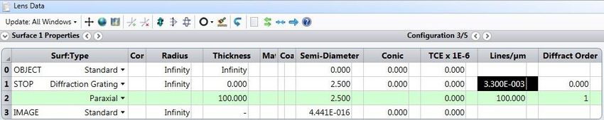
• α = 0.1o (More information about separation angle for even and odd orders can be found
 here)
 • Calculated Ʌ = 304.814 m
 • Lines/um = 1/ Ʌ = 1/ 304.814 = 0.0033 [Lines/ m]

 1.3.3. Holo/Or’s online grating calculator can be used:

 • https://www.holoor.co.il/optical-calculator/gratings-optical-calculator/ (section “Gratings”)

2. Three techniques to model diffractive beam splitters – two in sequential mode
 and one in non-sequential mode:
 2.1. Sequential mode - Method A: Diffraction grating surface and multi-configuration

 2.1.1. Development steps

 • Inserting general parameters for simulation (wavelength, aperture, etc.)
 • Inserting Diffraction Grating surface into Lens editor

 o Lines/ m (equivalent to grating period)
 o Diffraction order

 • Definition of Multi-Configuration Editor

 2.1.2. Example for 1D case of 5 spots splitter – diffraction orders - 2 to 2:

 Lens data editor view:

 2.1.3. Advantages of the method

 • Realistic physical model (consistent with Diffraction Grating equation)
 • Allows optimization of the optical system including diffractive beam splitter
Page | 3 Copyright © 2021 Holo/Or LTD.
 This document is the sole and exclusive property of HOLO/OR LTD.
 Not to be distributed or divulged without prior written agreement
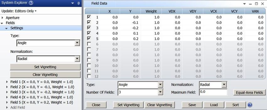
• Allows 2D beam splitter modeling

 2.2. Sequential mode - Method B: Field’s angle

 2.2.1. Development steps

 • Entering Fields’ angle in “System Explorer” (The field angles are equivalent to propagation
 angle of the Multi-Spot orders)

 2.2.2. Example for defining a 5-spot beam splitter with separation angle of 0.1 degrees:

 Lens data editor view:

 • Object surface contains two functionalities – a source and a multi-spot. Distance from multi-
 spot and the following optical surfaces can be defined by adding distance between surface 0
 and surface 1.

 2.2.3. Advantages of the method

 • Simplest way to build and analyze results
 • Allows optimization of the optical system including diffractive beam splitter
 • Allows 2D beam splitter modeling

Page | 4 Copyright © 2021 Holo/Or LTD.
 This document is the sole and exclusive property of HOLO/OR LTD.
 Not to be distributed or divulged without prior written agreement
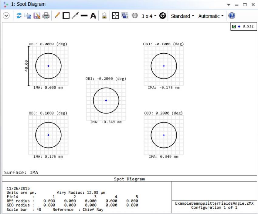
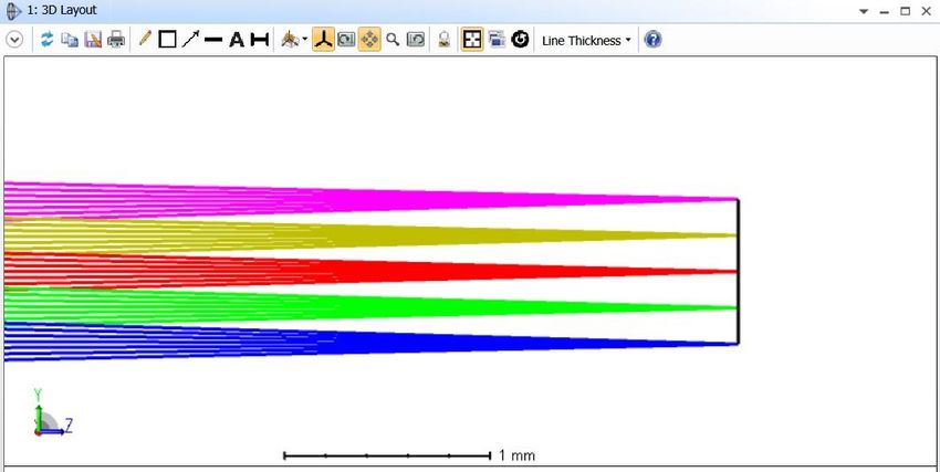
2.3. Sequential mode – displaying and analyzing results

 2.3.1. 3D Layout diagram:

 Settings for multi-configuration - Method A Settings for Field Angles - Method B

 Rays near focal position

 2.3.2. Spot diagram

 • Method A - Window’s setting definition in 3 steps:

Spot diagram in tools bar Choosing “All” configurations in opened window Settings of the window’s example

Page | 5 Copyright © 2021 Holo/Or LTD.
 This document is the sole and exclusive property of HOLO/OR LTD.
 Not to be distributed or divulged without prior written agreement
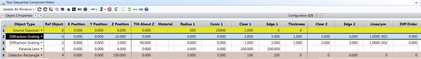
Spot diagram example

 • Method B - Window’s setting definition

 Window’s settings Spot diagram example

 2.4. Non-sequential mode – Method C: Diffraction Grating surface with special definitions

 2.4.1. Development steps

 • The design starts with the calculation of lines / m value.
 • Open a new file in NSC mode
 • Insert Source surface Define general properties of the design (wavelength …)
 • Number of “#Analysis Rays” and “# Layout Rays”
Page | 6 Copyright © 2021 Holo/Or LTD.
 This document is the sole and exclusive property of HOLO/OR LTD.
 Not to be distributed or divulged without prior written agreement
• Insert Diffraction Grating surface

 o Define basic parameters for the element (material, thickness, clear aperture)
 o Insert Lines / m parameter
 o Open properties of Diffraction grating surface and go to Diffraction property
 o In “Split” option choose “Split by DLL function” and then choose file diff_samp_1.DLL
 o Enter Start Order and Stop Order. For example, for 5 spots beam splitter -2 and 2
 o Insert period size in lines/µm units into reflection and transmission sections.

 * For a 2D beam splitter another Diffraction Grating surface needs to be entered with a 90 degrees
 rotation around the optical axis (typically “tilt Z”).
 ** For large number of orders, some modification in general properties of the non-sequential mode
 might be required to get correct results. Increase Maximum Segments per Ray value while you will get
 efficient number for the specific case.

Page | 7 Copyright © 2021 Holo/Or LTD.
 This document is the sole and exclusive property of HOLO/OR LTD.
 Not to be distributed or divulged without prior written agreement
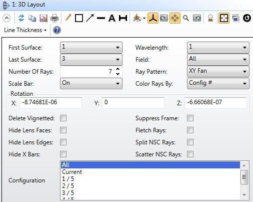
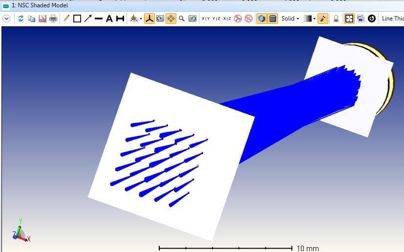
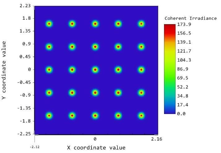
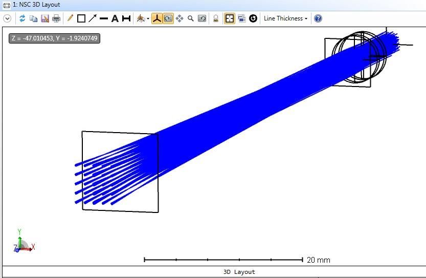
2.4.2. Advantages of the method

 • More realistic physical model (chromatic behavior)
 • Allows the modeling of all orders at once for a 2D beam splitter
 • Enables integration of a diffractive element into any optical system
 • Very useful for illumination systems

 2.5. Non-sequential mode - displaying and analyzing results

 2.5.1. NSC 3D Layout and NSC Shaded Model:

 • To see the diffraction orders, mark the option for “Split NSC Rays” in properties of 3D Layout
 and also for Ray Trace Control

 3D Layout and Shaded Model Ray Trace and Detector Viewer

 • Example - results for beam splitter array 5x5

 Shaded Model 3D Layout

Page | 8 Copyright © 2021 Holo/Or LTD.
 This document is the sole and exclusive property of HOLO/OR LTD.
 Not to be distributed or divulged without prior written agreement
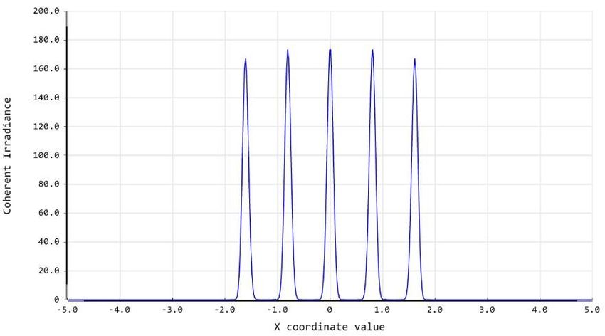
2.5.2. Ray Tracing Results

 False color (simulated in some defocus) Cross section

3. Methods comparison and summary
 3.1. Comparison table for sequential and non-sequential models

 Method A Method B Method C
 Ideal model Yes Yes Yes
 Geometrical method Yes Yes Yes
 Optimization of multi element optical system Natural Requires adaptation per wavelength Complex

 Aberration analysis Natural Natural Complex
 Simultaneous analysis of all spots No No Yes

 3.2. Summary

 3.2.1. Three methods to model Diffractive Beam Splitter in ZEMAX were shown
 3.2.2. The methods are based on geometrical concept and assume an ideal element
 3.2.3. The Sequential mode based methods benefit optimization and design capability by using multi
 configuration or field angles
 3.2.4. The Non-Sequential mode method brings more realistic result by allowing to propagate all
 spots at once
 3.2.5. The methods allow integration and analysis of Diffractive Beam Splitter within different optical
 systems design

Page | 9 Copyright © 2021 Holo/Or LTD.
 This document is the sole and exclusive property of HOLO/OR LTD.
 Not to be distributed or divulged without prior written agreement
4. Example files links and existing products from Holo/Or:
 4.1. Files

 • ExampleBeamSplitterMultiConfig
 • ExampleBeamSplitterFieldsAngle
 • MS-NS

 4.2. Available products

 http://holoor.co.il/Diffractive_Optics_Products/Diffractive_Beam_Splitters/BeamSplitter-
 multispot.htm

Page | 10 Copyright © 2021 Holo/Or LTD.
 This document is the sole and exclusive property of HOLO/OR LTD.
 Not to be distributed or divulged without prior written agreement
You can also read