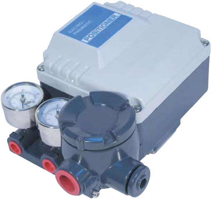
Electro-Pneumatic Positioner EPL Series - Instruction Manual 99.66.02-C GB
←
→
Page content transcription
If your browser does not render page correctly, please read the page content below
99.66.02-C
                                           GB

Electro-Pneumatic Positioner EPL Series
           Instruction Manual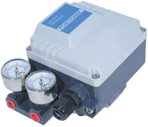
Electro-Pneumatic Positioner EPL Series
1. Read all safety instructions in this manual carefully before using this EPL positioner. All
work should be done by staff with the necessary training and experience.
2. The air filter regulator should be installed before this EPL positioner.
3. The EPL positioned approved for ATEX Eex md IIB T5 must be connected to a fuse with
the following ratings:
- Max 125mA, breaking capacity 35A
- Suitable 1/2” PF threaded, certified EEx d cable glands and plugs must be used.
1. Part Number System
Pressure
Pilot
Protection Feedback Gauge Position Connection High Mounting
EPL
Class Lever (SUP.
Valve
Feedback Threads Temp Bracket
Orifice
OUT)
Description Code Description Code
Protection Position
Class: F: Flameproof Ex md IIB T6 Feedback: N: None (standard)
D: Flameproof Ex md IIC T6 O: Position transmitter
A: Flameproof
(only for (4~20mA output signal)
weatherproof
Eex md IIB T5 ATEX type)
I: Intrinsic safety (Ex ia IIB T6)
W: Weatherproof to IP66
Connection
Feedback Threads:
3: PT 1/4 – PT 1/2 (standard)
Lever: A: stroke (10~40mm) (pneumatic 4: NPT 1/4 – NPT 1/2
B: stroke (10~80mm) – electrical) 5: PT 1/4 – M20 x 1.5
C: stroke (80~150mm)
Pressure High
Gauge: Temperature: T: 70ଇ (standard)
1: 6 bar (90 psi) H: 120ଇ
2: 10 bar (150 psi)
(only for
(without position feedback option)
weatherproof 85ଇ
type) (with position feedback option)
Pilot Valve
Orifice: S: Standard
(actuator volume over 180 ) Mounting
M: Small orifice (1.0 or 0.7) Bracket: N: None
(actuator volume 90~180 ) L: For DIN / IEC 534
2. Specifications
EPL
Linear Type (Lever Feedback)
Single Double
Input Signal 4~20mA DC (Note. 1)
Input Resistance 235 ± 15
Air Supply Max. 7.0bar (100psi) free of oil, water, and moisture
Standard Stroke 10~80mm (Note. 2)
Pneumatic Connections Rc 1/4 (NPT 1/4)
Electrical Connections Rc 1/2 (NPT 1/2)
Ex md IIB T6, Ex md IIC(H2) T6, IP66, Ex ia IIB T6
Protection Class
Eex md IIB T5 ATEX
Ambient Temperature -20~70ଇ
Clorius Controls A/S 2Electro-Pneumatic Positioner EPL Series
Pressure Gauge Stainless Steel
Output Characteristics Linear
Linearity Within ± 1.0 % F.S Within ± 1.5 % F.S
Sensitivity Within ± 0.2 % F.S Within ± 0.5 % F.S
Hysteresis Within ± 1.0 % F.S
Repeatability Within ± 0.5 % F.S
Air Consumption 5 LPM (Sup. 1.4kgf/່)
Flow Capacity 80 LPM (Sup. 1.4kgf/່)
Material Aluminum Die-cast
Weight 2.9 kg (with terminal box)
Note: 1) 1/2 spilt range is available for 4-12mA input signal or 12-20mA input signal.
2) Operating stroke can be extended up to 80~150mm.
3. Mounting and Selecting RA (reverse acting) or DA (direct
acting)
CAUTION: To reduce the risk of ignition of hazardous atmospheres, disconnect the device
from the supply circuit before opening. Keep assembly tightly closed during
operation.
A. Mounting and Attaching Feedback Lever
ཛ Mount the EPL positioner to the control valve as shown
to the right.
ཛྷ Fix the EPL positioner and the feedback lever to the control
valve stem at position where the angle between the valve
stem is settled to 90 degrees as shown below when the input
signal is set to 12mA (50%). Be sure that the elimination
spring should be installed.
ཝ The feedback lever A is for stroke 10૫40mm and the
feedback lever B is for stroke 10~80mm. For up to stroke
150mm, please connect a feedback lever A and a feedback
ever B with each other. The operation angle of the EPL
positioner is minimum 10 q and maximum 30 q .
Connect the feedback lever and the enclosed additional feedback lever with each other for a
stroke extension of over 80mm.
[Elimination Spring Installation]
B. Position of Span Adjuster According to Actuator Type (RA or DA)
Span adjuster is set to RA (reverse acting) as a standard factory setting. But it is necessary to re-set its position
for DA (direct acting) as shown below.
WARNING: When adjusting or replacing a span adjuster, be sure to shut off air supply to
the EPL positioner. Otherwise, the EPL positioner might react suddenly and
cause damage or injury.
Direct Acting (DA) Reverse Acting (RA)
Clorius Controls A/S 3Electro-Pneumatic Positioner EPL Series
4. Air Connections
5. Internal View
Auto/Manual screw
Stopper screw
Seat adjuster
Pilot valve
Output pressure gauge
Zero adjusting screw
Nozzle
Supply pressure gauge
Span adjusting screw
Terminal box
Feedback lever
Torque motor Case
Never move the seat adjuster. It was already set at the factory precisely.
Clorius Controls A/S 4Electro-Pneumatic Positioner EPL Series
6. Span and Zero Adjustment
ཛ Check the proper installation of the EPL positioner and the feedback lever.
ཛྷ Check the proper position of a span adjuster according to the actuator type (direct acting or reverse acting).
ཝ Connect all air connections.
ཞ Supply air and set the input signal to 4mA. Turn the zero adjusting screw clockwise or counter clockwise to set the
zero position.
ཟ Check the stroke of the control valve by setting the input signal to 20mA. If the stroke does not meet 100%, turn the
span adjusting screw clockwise or counter clockwise until 100% is reached.
འ Set the input signal back to 4mA and adjust the zero adjusting screw until the zero point is reached.
ཡ Repeat the process of ཞ to འ until the desired set points are reached.
ར If the strokes of the control valve perfectly meet 0% and 100%, each setting point of 8, 12, and 16mA is
automatically reached.
NOTE: Due to variations in circuitry and environmental effects, often 0% is set at 4.5mA and
100% at 19.5mA to make sure that at the end points the valve will be fully open or
fully closed.
7. Wire Diagrams
CAUTION: Always check that the electrical load is within the range stated on the nameplate.
Failure to remain within electrical ratings may result in damage to or premature
failure of the electrical switches, sensors or transmitter electronics.
NOTE: For the ATEX-approved product, please connect a fuse with the ratings of Max.
125mA, breaking capacity 35A and suitable 1/2” PF threaded certified EEx d cable
glands and plugs must be used.
Clorius Controls A/S 5Electro-Pneumatic Positioner EPL Series
8. Position Transmitter (4…20mA output signal)
A. Board View
ٻ
ٻ
B. Specifications
Power Supply Rating 5.5~30V DC loop-powered
Recommended Power Supply 24V DC
Output Signal 4~20mA
Operating Temperature -20º to 70ଇ
Load Impedance 0~600 ohms
Max. Output 30mA DC
Linearity ± 1.0 %
Hysteresis 1.0 % of full scale
Repeatability ± 0.5 % of full scale
Adjustment Zero and Span in terminal box
C. With mA loop calibrator D. With multimeter tester
E. Span and Zero Adjustment
ཛ Select RA or DA on a board in the terminal box. For reference, RA (reverse acting) is a standard factory setting.
ཛྷ Supply 4mA input signal and turn the zero adjusting screw on a board clockwise or counter clockwise until output signal
becomes 4mA.
ཝ Supply 20mA input signal and turn the span adjusting screw on a board clockwise or counter clockwise until output
signal becomes 20mA.
ཞ Repeat the process of ཛྷ to ཝ until output signal approaches input signal.
1. Be sure that Span and Zero of the EPL positioner should be exactly set before
setting Span and Zero of the position transmitter.
2. Be sure that 5.5 - 30VDC should be supplied in case of using the mA tester
(multimeter tester).
3. Check a loop power if the output power indicating lamp འ is not on.
9. Optional Restricted Pilot Valve Orifice
WARNING: Before removing the pilot valve, be sure to
disconnect the EPL positioner from the signal and
compressed air source
For improved control using smaller actuators, a restricted pilot valve orifice kit is
included with the EPL positioner. To install, the pilot valve must be removed from the
EPL positioner. Remove four screws holding the pilot valve to the EPl positioner
body. As you remove the pilot valve, be sure to hold the compensation spring in
place. Flip the valve so the bottom faces you. Remove the o-rings from the out 1
and out 2 ports (as shown in the diagram at right). Place the orifice plates in their
place with new O-rings above them, and re-install the pilot valve, making sure the
compensation spring is back in place. The EPL positioner is now set up for smaller actuators.
Clorius Controls A/S 6Electro-Pneumatic Positioner EPL Series
10. Troubleshooting Tips
Troubles Solutions
There happens a hunting with a Install two orifices at the bottom of the pilot valve as instructed in 12.
small pneumatic actuator Optional Restricted Pilot Valve Orifice
The orifice of the Auto/Manual screw on the pilot valve is clogged.
Disconnect supply air and clean the orifice with a wire attached inside of
the EPL positioner cover as shown below.
The valve always opens
regardless of input signal.
Never move the seat adjuster. It was already set at the factory
precisely.
The air connections are not made properly. Check again if the pneumatic
The valve always opens or
actuator type is RA (reverse acting) or DA (direct acting) and make the
closes with input signal
proper air connections. See 7. Air Connections.
Linearity is very poor Re-set Zero and Span.
Hysteresis is very poor Tighten a mounting bracket.
11. Dimensions
འ
Clorius Controls A/S 7Clorius Controls A/S Tempovej 27 DK-2750 Ballerup Denmark Tel.: +45 77 32 31 30 Fax: +45 77 32 31 31 www.cloriuscontrols.com
You can also read