From the herringbone dome by Sangallo to the Serlio floor of Emy
←
→
Page content transcription
If your browser does not render page correctly, please read the page content below
Curved and Layer. Struct. 2021; 8:259–270

Research Article

Giulio Mirabella Roberti*, Giuseppe Ruscica, and Vittorio Paris

From the herringbone dome by Sangallo to the
Serlio floor of Emy (and beyond)**
https://doi.org/10.1515/cls-2021-0023
Received Oct 01, 2020; accepted Mar 09, 2021
                                                                              1 Introduction
Abstract: The research starts from an analogy found be-                       The starting point of this research is the similarity between
tween two apparently very different structural solutions:                     two very different structural solutions such as the cross-
the double spiral pattern of the herringbone brick courses                    spiral pattern of the herringbone brick course in the domes
in the domes built by Antonio da Sangallo the Younger                         built by Antonio da Sangallo the Younger (1484-1546) during
(1484-1546) during the Renaissance, and the particular pat-                   the Renaissance [1–3], and the particular pattern of wooden
tern of a wooden floor ‘à la Serlio’, described by Amand                      beams in the ‘à la Serlio’ floor described by Amand Rose
Rose Emy in his Treatise at the beginning of 19th century,                    Emy in his Treatise at the beginning of 19th century [4],
made by diagonal beams reciprocally sustained. The di-                        made by diagonal beams reciprocally sustained.
agonal pattern of the floor has a geometrical relationship                         The secret building process of the dome of the Santa
with the cross-herringbone pattern, so that the latter can                    Maria del Fiore cathedral in Florence (1418-1471) has fasci-
be obtained by some geometrical transformations of the                        nated researchers for around six hundred years, but the
former. This pattern was also used in thin shells built by                    procedure for the construction of this impressive structure
Nervi, from the destroyed airplane hangars in Tuscany to                      remains a mystery. The origins of the herringbone construc-
the Palazzetto dello sport in Rome, and even by Piacentini                    tion technology have been hidden by the fame of the dome
in 1936 and earlier in some neoclassical domes.                               of Santa Maria del Fiore. It is unreasonable to think that Fil-
Thus the construction tool, useful for building domes with-                   ippo di Ser Brunellesco Lapi (1377-1446), commonly known
out expensive scaffolding, could have a structural role at                    as Brunelleschi, built his masterpiece without having a full
the completed construction stage. Within the research dif-                    grasp of the spiraling herringbone technology, that allowed
ferent structures were investigated, in order to observe the                  a relatively fast building process of the dome without the
relevance of this peculiar structural scheme particularly in                  need of a complete centering. Some researchers trace its
the construction of modern domes.                                             origins to the East, based on the cultural contact that was ev-
                                                                              ident between the Florentine, Byzantine and Arab cultures.
Keywords: conceptual design, masonry domes, herring-
                                                                              After Brunelleschi, up until the second half of the 16th cen-
bone pattern, reciprocally supported beams, ‘Serlio’ floors,
                                                                              tury, the spiraling herringbone technique was used system-
metal spatial structures, membrane stiffening
                                                                              atically by the Florentine architects Sangallo [5]. The San-
                                                                              gallo perfected this building technology, developing a dou-
                                                                              ble pattern of herringbone bricks: the cross-herringbone [6]
                                                                              (see Figure 1).

*Corresponding Author: Giulio Mirabella Roberti: University
of Bergamo, 5, G. Marconi Street, 24044 Dalmine BG, Italy; Email:
giulio.mirabella@unibg.it
Giuseppe Ruscica, Vittorio Paris: University of Bergamo, 5, G.                Figure 1: Right: herringbone pattern. Left: crossed-herringbone
Marconi Street, 24044 Dalmine BG, Italy                                       pattern
** Paper included in the Special Issue entitled: Shell and Spatial
Structures: Between New Developments and Historical Aspects

  Open Access. © 2021 G. Mirabella Roberti et al., published by De Gruyter.                     This work is licensed under the Creative Commons
Attribution 4.0 License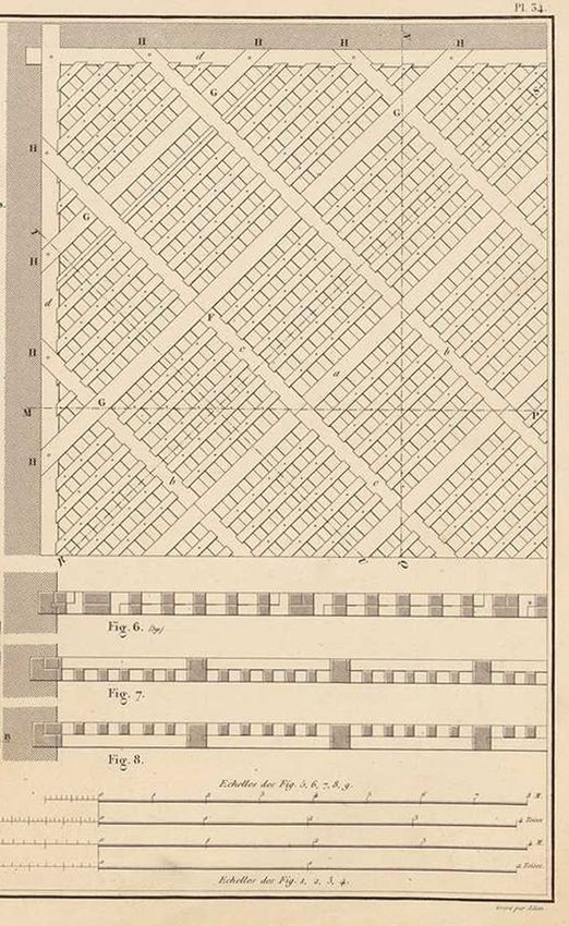
260 | G. Mirabella Roberti et al.

     As shown in Figure 1, the spiraling herringbone con-         beams shorter than the span, sustaining each other in a re-
sists of an arrangement of stretcher brick courses (laid hori-    ciprocal way. The floor described in table 34 of the Treatise,
zontally at the springing) interrupted by soldier bricks (laid    see Figures 3 and 4, was built in Corbeil, France, at the end
vertically), forming a herringbone pattern with the above         of 18th century for a flour warehouse. It has the particularity
and underlying course. As shown in Figure 2, throughout           of being a square grid made by diagonal beams, each one
the different courses, the soldier bricks describe a peculiar
path: a loxodromic curve, forming a constant angle with
meridian lines, also called rhumb line (from marine science
or Mercator track, in Geography).

Figure 2: Herringbone pattern of a hemispherical dome during
construction works. Original drawing by F. Gurrieri, 1982

     Antonio da Sangallo the Younger developed a particu-
lar arrangement by crossing two herringbone patterns start-
ing at the base from the same points, but one clockwise
and the other anticlockwise [3]. Rowlock bricks were used
instead of soldiers, composing a very regular (and symmet-
rical) pattern on the surface that could also balance some
stability problems highlighted by Brunelleschi’s dome [7].
Indeed, the dome of Santa Maria del Fiore displays a crack
pattern that is affected by herringbone pattern [8].
     This solution can still be observed in two similar domes
built by Sangallo: the dome of Santa Maria in Ciel d’Oro [9],
in Montefiascone, and the dome of Simon Mago, one of              Figure 3: Table 34 of Emy’s Treatise: the Corbeil floor
the eight ‘octagonal rooms’ around the central dome in the
St. Peter’s Basilica in Rome, located over the barrel vaults
connecting the lateral arms of the transept with the choir
by means of the round corner chapels.
     We had the opportunity to survey both, combining
laser-scanning and photogrammetric techniques, under
the direction of prof. A. Pizzigoni [10, 11]. The geometry and
the masonry texture provided by this survey constituted
the basis for the numerical simulations described later.
     The second suggestion is a particular grid floor de-
scribed by A.R. Emy [4] in his Treatise on the art of carpentry
at the beginning of 19th century, in the chapter concerning       Figure 4: Detail of intrados connection of the Corbeil floor
the so-called ‘à la Serlio’ floors, that are floors composed by
From the herringbone dome by Sangallo to the Serlio floor of Emy (and beyond) |       261

covering two panels, strongly connected at the end by tie           ments remain to describe the herringbone technique, that
rods in tension to ensure flexural continuity.                      are currently preserved at the Uffizi Museum. The first is
     So, a question arises: is there a relationship between         the drawing 900A (n. 639051) GDSU (Gabinetto dei Disegni
the two solutions? Or else, provided that a geometrical tran-       e Stampe Uffizi) and the second drawing 1330 (n. 594469)
sition from the flat floor to the hemispherical dome can            GDSU [9]. Both documents are associated with the San-
be demonstrated, is there the possibility that the cross-           gallo architects, and illustrate the herringbone or the cross-
herringbone bricks can involve a structural function also           herringbone spiralling technologies.
when the dome is completed?                                               Among the domes built by the Sangallo which are
     Many intermediate solutions appear to confirm this pos-        still standing, two are particularly interesting, the dome of
sibility: the well-known Orbetello hangars by P.L. Nervi (Fig-      Santa Maria in Ciel d’Oro in Montefiascone (Viterbo) [20]
ure 14b), for example, used a crossed loxodromic pattern            and the dome of Simon Mago room in San Pietro cathedral
of diagonal arches having the same span on a barrel vault,          in Rome (see Figure 5): they show how the Sangallos – and
keeping it strong and light; the flat dome of the Palazzetto        especially Antonio the Younger – have contributed to the
dello Sport in Rome (Figure 6d) also uses loxodromic paths
for the shell ribs, creating a beautiful and vibrating effect
on the surface.
     In order to investigate the reliability of our hypotheses,
a few analyses have been performed using FEM Straus7 soft-
ware [12, 13]. Moreover, Discrete Element Method (DEM) [14,
15] simulations have also been performed for the Simon
Mago dome. The choice of two different numerical ap-
proaches is due to the very different characteristics of struc-
tures analysed, DEM simulation is adopted to investigate
masonry structures [16], where discontinuities are assumed
to be relevant to the mechanical behaviour, while beam and
truss systems are better described through Finite Element
Method analyses [17].

2 Geometry and history
2.1 Historical references

The literature on the application of herringbone spiralling
technology for Brunelleschi’s dome: Santa Maria del Fiore
in Florence, is quite extensive [1, 18]. Although it is still not
very clear how Brunelleschi gained his knowledge on this
technology, his work has highly influenced the diffusion
and the affirmation of the application of the herringbone
spiralling technique in central Italy during the Renaissance.
Undoubtedly, well before Brunelleschi’s Masterpiece was
built, this technology was seen applied within the Arabic
region [19] as testified by domes of Isfahan Friday Mosque
(1088) or Ardestan Friday Mosque (1158) in Iran.
     In Europe, the most significant contribution to the
knowledge and development of the herringbone spiralling
technology was provided by a Florentine family of archi-
tects and master masons: the Sangallo. Despite a large              Figure 5: Survey of Simon Mago dome (San Pietro basilica), the
spread at the time of this method of construction, it dis-          loxodromic curve highlighted in red. Orthographic projections, top:
                                                                    half-section view, bottom: one-quarter hyposcopic view
appeared quite quickly, and today only two original docu-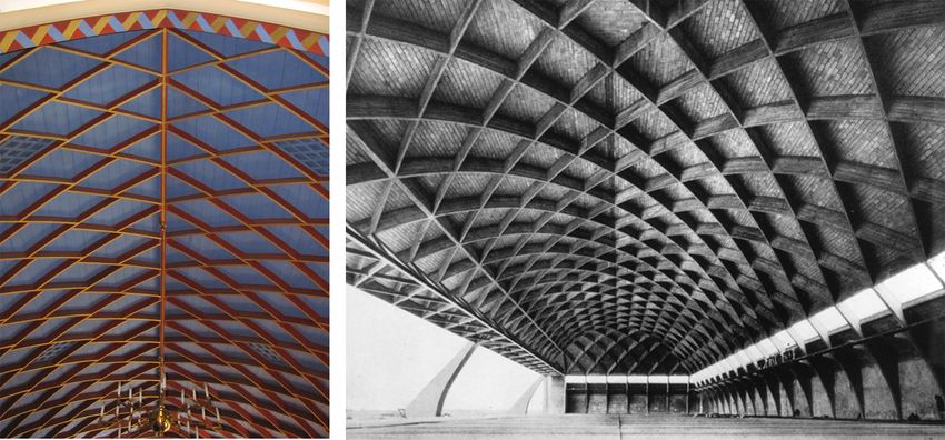
262 | G. Mirabella Roberti et al.

Figure 6: Comparison between different rib patterns in domes from antiquity to present

diffusion of the herringbone spiralling technique. They not meridian-parallel structure is highlighted: but in the sec-
only systematically applied this technique for the construc- ond one the octagonal shape of the ‘lacunari’ underlines
tion of domes, but they also perfected it. This research of the need of a diagonal stiffening, like that depicted in the
the Sangallo family then further led to developing an even ‘Rotunda’ of Mosta. Here the basket-like structure, made
more advanced construction system: the cross-herringbone by crossed loxodromic ribs, is only painted on the surface
spiralling technology. Both of these methods allow to build of a hemispherical dome, but the examples of Piacentini
masonry domes without any centering to support the dead and Nervi show two shallow shells, where these ribs have
load during the construction, but even today, the role and a relevant structural role.
long term advantages of cross-herringbone construction
technique in terms of its structural behaviour is not ex-
plored.                                                         2.2 Geometries
     As already mentioned, the peculiar topology visible
in Simon Mago dome of Saint Peter Basilica (Rome), illus- Surfaces such as planes, cylinders, cones or spheres are
trated in Figure 5, can also be found in other shell structures undoubtedly different; their mathematical description in-
after the Renaissance, but not in the classical ones of the volves different equations. For example, planes are defined
Pantheon or the thermal dome of St. Bernardo in Rome.           by a linear equation and cylinders’ geometry by a quadratic
     In Figure 6 a quick comparison of five different domes one but, precisely as cones and spheres, all geometries can
is presented. In the Roman domes (like the Pantheon or the be generated by rotating a planar curve around a fixed axis.
thermal dome of St. Bernardo, rebuilt in 1598) a classical Hence, denoting the matrix of rotation by R, all surfaces Σ

Figure 7: Different geometries and relative loxodromic curves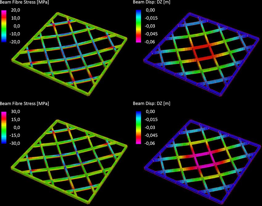
From the herringbone dome by Sangallo to the Serlio floor of Emy (and beyond) |      263

shown in Figure 7 can be described through the rotation of
a plane curve, called generatrix Γ g , around an axis r, see (1).

                           Σ = RΓ g                          (1)

All geometries drawn in Figure 7 and many others can be
obtained through the revolution operation (1). For such
class of surfaces, it is possible to write the equation of loxo-
dromic curves explicitly. Loxodromic curves Γ l , also called
rhumb lines, constitute one-dimensional entities which lay
on revolution surfaces and are strictly related to them [21].
     Their main property is the following: for any point P
belonging to the loxodromic curve, the angle α between the
tangent versor of the generatrix curves of the related surface
and the tangent versor of the loxodromic itself remains
constant, that is:

        Γ ′g P        Γ ′l P
            (︀ )︀         (︀ )︀
      ⃦ ′ (︀ )︀⃦ · ⃦ ′ (︀ )︀⃦ = k (costant) ∀P ∈ Σ ∧ Γ ′l (2)
      ⃦Γ g P ⃦ ⃦Γ P ⃦
                       l
                                                                    Figure 8: Left half dome: top view of common masonry pattern.
Undoubtedly, due to eq. (2), the curve used for tracing             Right half dome: top view of cross-herringbone masonry pattern
routes in the navigation field [22] is a loxodrome of the
sphere representing the Earth. Nevertheless, along the his-
tory, the geometry of the rhumb lines found several appli-               In order to estimate the effect of herringbone pattern
cations in defining the shape of architectural or structural        on hemispherical masonry dome, DEM analyses were per-
elements. When this occurs, they may enable to confer in-           formed using the 3DEC software [23]. Through this numeri-
teresting peculiarity to the structures in which they were          cal approach masonry structures are described by a system
applied, e.g. in the case of Santa Maria del Fiore in Flo-          of rigid bodies, and phenomena as sliding, overturning and
rence [6]. Furthermore, structures, where the loxodromes            even collisions between blocks are considered [14, 15].
geometries are used as the structural scheme, are composed               In the analyses carried out, the geometry of each block
of structural elements that belong to the same structural           has been defined by the same volume occupied by one brick
hierarchy level. Within this research, different loxodromic         plus a portion of mortar that surrounds it. Hence, the sys-
trajectories are assumed as primary structural systems for          tem of rigid bodies is composed by the same number of
different geometries, but all obtained by eq. (2).                  bricks illustrated in domes modelled in Figure 8. Further-
                                                                    more, all simulations were performed considering a finite
                                                                    value of friction angles ϕ = 25∘ , and the interfaces between
                                                                    the blocks are governed by the Mohr-Coulomb failure cri-
3 Numerical analyses                                                terion, without cohesive or tension capacity. The normal
                                                                    JKn and shear JKs stiffness parameters are defined as [24],
3.1 Analysis of the Sangallo dome                                   and they are related respectively to the difficulty of pressing
                                                                    and slipping of the blocks with respect to each other. As
Herringbone and cross-herringbone technologies played               shown in Figure 9, DEM analyses have been carried out
an essential role during the construction stages of masonry         on two hemispherical domes, whose diameter is 9,50 m,
domes [6]: due to their pattern, the rowlock bricks work            thickness equal to 0,28 cm and loaded only by self-weight
linking two different masonry courses. Proceeding to lay-           (18.00 kN/m3 ); so, according to Heyman’s theory [25], they
ing of completed brick courses, the masons built the dome           can easily stand up. Thus, the two models present the same
without using temporary support. In this sense, the role of         geometrical parameters and the same shell thickness. The
the double system of loxodromic curves does not change              only difference is the masonry pattern: one has the cross-
with respect to the single herringbone trajectory, indeed, to       herringbone pattern which model is based on the survey
reach a self-balanced state, the two construction systems in-       executed on the dome of Simon Mago in San Peter Basil-
volve the same resistant structure: the plate bande confined        ica (Rome) [11], and the other shows a common masonry
by soldier (or rowlock) bricks.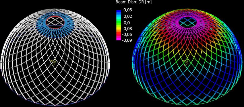
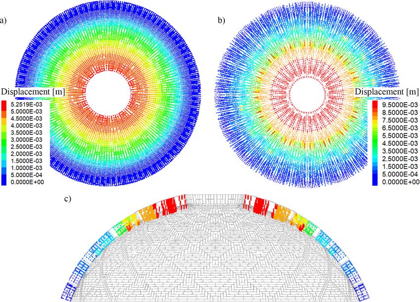
264 | G. Mirabella Roberti et al.

Figure 9: Map of displacement distributions: a) displacements of a dome with common masonry pattern. b) and c) displacements of a dome
with cross-herringbone. The complex geometry leads to the sliding of some blocks (displacement 1.0×10⁻² meters)

Figure 10: Hoop stresses on vertical joints. a) Common tessellation, the magnitude of stresses increases from the bottom to the crown.
b) Cross-herringbone model. The magnitude of stresses increases from bottom to the crown, but in correspondence of rowlock blocks
(delimited by black quotes) the normal stress is high regardless of the position of the block
From the herringbone dome by Sangallo to the Serlio floor of Emy (and beyond) | 265
tessellation. The simulations were performed only at the lations, truss elements have been disposed along the loxo-
completed construction stage. dromic patterns, and membrane elements have been used
As illustrated in Figure 9, the two models exhibit the to represent the continuity of the shell. The final goal is to
same displacement map: the movements increase from the verify if the same pattern adopted in Renaissance domes
base to the top, but in the case of the cross-herringbone can be used to build modern lattice domes: as a first attempt
model, the magnitude is about two times bigger than the FEM analyses were executed with pinned joints and reticu-
common tessellation. Furthermore, near the crown, the lar elements with the purpose to understand the influence
cross-herringbone model shows some irregularity in terms of such a structural choice.
of displacement map. Usually in lattice domes, such as the geodesic domes
The diversity of masonry patterns cannot entirely ex- built by Buckminster Fuller, the geometrical solutions are
plain the difference of magnitude and the irregularities all based on triangular faces formed by truss elements, so
in the displacement map. DEM allows considering rigid that pinned joints (connecting six or five elements) can be
bodies constituted only by planar faces; thus, due to the used. Moreover, the truss elements connected to a joint do
complexity of the cross-herringbone tessellation and the not belong to the same plane. Here, the loxodromic pat-
dome’s double curvature, geometrical incongruences near tern defines rhomboidal meshes and, as expected, even if
the crown are determined. This approximation is even high- the nodes of each rhomboid do not lie on the same plane,
lighted in the cross-herringbone model, where the tessella- the dome is not statically determined. Thus, as shown in
tion is more complex and leads to local sliding phenomena. Figure 11 and 12, additional stiffness must be provided by
Indeed, in the lower portion of the dome and even in the tension and compression rings, or by membrane elements;
central one, the difference of displacements between the the two solutions together were adopted.
two models is negligible. Therefore, a FEM model has been set up using differ-
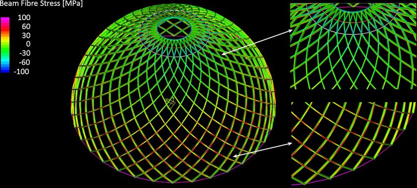
From the stresses point of view the two models do not ent connection solutions to reach a satisfying deforma-
show large differences, at least in the direction of the merid- tion/stress response to simple vertical loads, such as dead
ian. The normal stresses distribution on the vertical joints loads (see Figure 11 and 12). A more extended analysis
(those relating to the hoop forces) instead show differences: would be requested to assess the structural performance,
even if the magnitude is equal, the simulations highlight since these are only preliminary considerations to explore
perturbations, see Figure 10. The cross-herringbone model, this solution’s possibilities, especially in comparison to a
Figure 10b), shows alterations especially in correspondence standard ‘meridians-and-parallels’ structural system.
with herringbone bricks, where the hoop forces are concen- But more interesting is the possibility to apply the same
trated. solution adopted in the Serlio floor of Emy treatise, that is
to make the elements (spanning two meshes) reciprocally
sustained, like those of the Zollinger roofs, as described
3.2 Analysis of a lattice dome later in Section 3.4.
A second investigation was conducted on the same hemi-
spherical geometry adopted in Section 3.1. In these simu-
Figure 11: The lattice dome. Left: truss elements with upper compression rings and lower tension ring. Right: the same with membrane
elements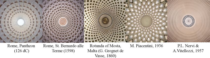
266 | G. Mirabella Roberti et al.

Figure 12: Shell displacements. Left: axial forces in truss elements. Right: Membrane stresses in hoop direction tangent to the surface
(purple = tension, blue = compression)

3.3 Analysis of the Emy floor                                         scribed in his Treatise, both on the hypothesis of a full
                                                                      continuity reached by the connection ties disposed on the
Loxodrome geometries are found even in the model de-                  bottom of crossing elements (see the detail in Figure 4), and
scribed by A.R. Emy. Here FEM analysis has been performed             in the situation of a hinged connection among intersecting
to investigate the efficiency of the beam arrangement de-             beams at their support, using the scheme of reciprocal sup-

Figure 13: Top left: Stresses due to axial forces and bending moments (fibre stresses) in the continuous grid beams. Top right: beam
displacements in vertical direction for the continuous beams grid. Bottom left: Stresses due to axial forces and bending moments (fibre
stresses) in the reciprocal frame roof. Bottom right: beam displacements in vertical direction for the reciprocal frame roof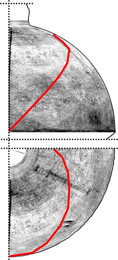
From the herringbone dome by Sangallo to the Serlio floor of Emy (and beyond) |          267

ported beams depicted by Emy neglecting the contribution                3.4 Examples of Emy-like shells
of connection ties.
     The two 7m × 7m frames were subjected to the same                  In the past, reciprocal frame structures were conveniently
uniformly distributed load of 4 kN/m2 , and the beams had               used thanks to the possibility to span large spaces with
the same geometry, and the elastic properties of the mate-              short elements. Beyond the 19th century roofs, described
rial were equally the same. The results are quite interesting:          by A.R. Emy, in 1921 Friedrich Zollinger patented a “lamella
for the reciprocal frame the vertical displacements increase            roof” (also known as the “Zollinger roof”, see Figure 14),
only by 25% compared to the fully fixed one and the flexu-              which consisted of a series of wooden boards [26], con-
ral stresses increase by 38%, showing not only the greater              nected with each other according to the topology of a canon-
efficiency of the continuous frame, as expected, but also a             ical reciprocal frame structure. It can be noticed that the
quite acceptable solution for the discontinuous reciprocal              geometry of Zollinger’s barrel vaults [27] resembles P.L.
frame (see Figure 13).                                                  Nervi’s Orbetello and Orvieto hangars (see Figure 14).
                                                                             Recently, the use of reciprocal frame structures has
                                                                        come to a new life, thanks to the continuous architecture’s
                                                                        quest for efficient structural forms of the past. A few exam-

Figure 14: Left: Zollinger roof in the Lutherhaus in Kötzschenbroda, Germany (photograph by Radobyl, distributed under a CC-BY 2.0
license). Right: Pier Luigi Nervi’s Orvieto Airplane Hangar (https://quod.lib.umich.edu)

Figure 15: Left: Hale County Animal Shelter by Rural Studio (http://ruralstudio.org). Right: ”Tij” bird observatory by Geometria Architecture
Ltd (https://geometria.fi)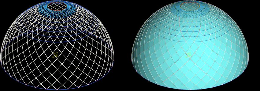
268 | G. Mirabella Roberti et al.

Figure 16: Left: Dome with reciprocal frame beam elements. Right: displacements in radial direction

Figure 17: Left: Stresses due to axial forces and bending moments (fibre stresses) in the reciprocal frame beams. Top right: detail of ele-
ment stresses in the upper part. Bottom right: detail of element stresses in the lower part

ples are constituted by some small pavilions of Geometria them spanning two romboidal meshes, without the struc-
Architecture Ltd architectural practice and the Hale County tural contribution of the membrane elements. Only the top
Animal Shelter by Rural Studio (see Figure 15).               and bottom annular ring were left in order to give the nec-
     These considerations show that reciprocal frames and essary stiffness in compression and tension, respectively.
herringbone domes share the same principles of struc- The dome was subjected to a distributed vertical load of 1
tural efficiency and attention to the load paths, both im- kN/m2 on horizontal projection, giving the results shown in
portant aspects when considering historical constructions. Figures 16 and 17. Both displacements and stresses appear
Although the structures above seem far different from the to be adequate.
ones reported in the previous sections, they all employ lox-
odromic curves as underlying geometry for the principal
structural scheme.
     In the attempt to apply these solutions to hemispherical
domes, the same lattice shell of sect. 3.2 (with 20m diame-
ter) was studied making use of reciprocal beams, each of
From the herringbone dome by Sangallo to the Serlio floor of Emy (and beyond) | 269
Conflict of interest: The authors state no conflict of inter-
4 Conclusions and further est.
developments
The research is still not concluded. However, loxodromic
geometries show how fascinating these elements appear
References
in any observed structures. Unlike a common frame-like [1] Di Pasquale S. La costruzione della cupola di Santa Maria del
structure, the system of crossed loxodromic ribs affects and Fiore. Venezia: Marsilio; 2002.
involves a major quote of the shell surface. The orientation [2] Acidini Luchinat C, editor. La cattedrale di Santa Maria del Fiore
of spiral geometries leads to a structural behaviour more a Firenze. Vol. 2. Firenze: Cassa di Risparmio di Firenze; 1995.
similar to that of the shell, giving to the surface an intrinsic [3] Giovannoni G. Antonio da Sangallo il Giovane. Vol. 1. Tipografia
regionale; 1959.
in-plane stiffness.
[4] Emy AR. Traité de l’art de la charpenterie. Vol. 1. Paris; 1837.
From a merely structural point of view, their presence [5] Zander G. Gli ottagoni di San Pietro riconosciuti nel dis. Arch. Uff.
(see Section 3.1) in the masonry dome could appear ineffec- n. 1330. Palladio. 1988;1:67–82.
tive, increasing the displacements at the top compared to [6] Paris V, Pizzigoni A, Adriaenssens S. Statics of self-balancing
the usual brick disposition; but observing the building and masonry domes constructed with a cross-herringbone spiraling
pattern. Engineering Structures. 2020;215:110440.
technological aspects, the cross-herringbone system offers
[7] Chiarugi A, Foraboschi P. Monitoraggio e identificazione della
enormous advantages. Indeed, these patterns are not con- cupola di Santa Maria del Fiore. L’Edilizia. 1993;20–42.
ceived originally as stiffener ribs, but rather as constructive [8] Bartoli G, Betti M, Borri C. Numerical modeling of the structural
aids. At the beginning, they have been probably introduced behavior of Brunelleschi’s dome of Santa Maria del Fiore. Inter-
as decorating elements, and then gradually became more national Journal of Architectural Heritage. 2015;9(4):408–29.
and more structurally effective, as well as the comprehen- [9] Pizzigoni A, Paris V, Ruscica G. Herringbone technique: truth and
history of a cutting-edge technology. Proceedings of IASS An-
sion of structural behaviour of shells became more and
nual Symposia, IASS 2018 Boston Symposium: Historical spatial
more deep. structures. 2018;1–8.
That is why, throughout history, several architects con- [10] Paris V. On the equilibrium of self-balanced shells under con-
ceived their structures taking into account the use of loxo- struction [Doctoral dissertation]. University of Bergamo; 2020.
dromic geometries. If we look even further, this geometric [11] Pezzoli D. Il dispositivo “spinapesce” per la costruzione di volte
in muratura nella tecnologia rinascimentale dei Sangallo [Master
pattern can adequately be used in reciprocal frames, merg-
thesis]. 2019.
ing the loxodromic curves into the “Emy floor” schemes [12] HSH s.r.l. Straus7. HSH s.r.l.; 2013.
or, as a further development, even into deployable struc- [13] Cook RD, Malkus DS, Plesha ME, Witt RJ. Concepts and Applica-
tures, like the well-known Chuck Hoberman’s “Iris Dome” tions of Finite Element Analysis. John Wiley & sons; 2007.
[28, 29], which has been exhibited at the New York’s Mu- [14] Cundall PA. Formulation of a three-dimensional distinct element
seum of Modern Art (MoMA) in 1994. model—Part I. A scheme to detect and represent contacts in
a system composed of many polyhedral blocks. International
Journal of Rock Mechanics and Mining Sciences & Geomechanics
Acknowledgement: The fundamental help of Dr. P. Azzola Abstracts. 1988;25(3):107–16.
in the survey operations and restitution process is grate- [15] Hart R, Cundall PA, Lemos J. Formulation of a three-dimensional
fully acknowledged, as well as the work done by MSc stu- distinct element model—Part II. Mechanical calculations for mo-
dent D. Pezzoli for his graduation thesis; the critical discus- tion and interaction of a system composed of many polyhedral
blocks. International Journal of Rock Mechanics and Mining Sci-
sion with prof. A. Pizzigoni stimulated a widening of the
ences & Geomechanics Abstracts. 1988;25(3):117–25.
research. [16] Lemos JV. Discrete element modeling of masonry structures. In-
ternational Journal of Architectural Heritage. 2007;1(2):190–213.
Funding information: The authors acknowledge the finan- [17] Bathe KJ. Finite element procedures. books.google.com; 2006.
cial support from STaRs Programme 2020 of the University [18] Sanpaolesi P. Brunelleschi. Milano: Edizioni per il Club del libro;
of Bergamo. Software 3DEC [23] was provided by Itasca C.G. 1962.
[19] Galdieri E. Da Gerusalemme a Dakha: mille anni di cupole is-
under the Education Partnership Program, for which the
lamiche. In: Conforti C, editor. Lo specchio del Cielo. Milano:
authors also express their gratitude. Electa; 1997. p. 53–66.
[20] Paris V, Pizzigoni A, Ruscica G. Brunelleschi’s herringbone
Author contributions: All authors have accepted responsi- hidden reciprocal structure and the form finding of its self-
bility for the entire content of this manuscript and approved supporting bricks. Proceedings of IASS Annual Symposia, IASS
2017 Hamburg Symposium: Historic Shell & Spatial Structures.
its submission.
2017;1–10.270 | G. Mirabella Roberti et al.
[21] Loria G. Curve sghembe speciali, algebriche e trascendenti. Vol. [26] Weller B, Tasche M, Baatz J. Lamella Roof Constructions by Hugo
I: Curve algebriche. Bologna: Zanichelli; 1925. Junkers. Proceedings of the International Association for Shell
[22] Conti G, Corazzi R. Il segreto della Cupola del Brunelleschi a and Spatial Structures (IASS) Symposium 2009, Valencia. 2009.
Firenze – The Secret of Brunelleschi’s Dome in Florence. Firenze: [27] Franke L, Stahr A, Dijoux C, Heidenreich C. How does the Zollinger
Pontecorboli Editore; 2011. Node really work? Proceedings of the IASS Annual Symposium
[23] Itasca Consulting Group, Inc. 3DEC. Itasca Consulting Group, Inc.; 2017. 2017.
2020. [28] Hoberman C. Reversibly expandable doubly-curved truss struc-
[24] Simon J, Bagi K. Discrete element analysis of the minimum thick- ture. United States; 4942700, 1990.
ness of oval masonry domes. International Journal of Architec- [29] Hoberman C. Radial expansion/retraction truss structures.
tural Heritage. 2016;10(4):457–75. United States; 5024031, 1991.
[25] Heyman J. The stone skeleton: structural engineering of masonry
architecture. Cambridge University Press; 1995.You can also read