Noise mitigation for the construction of increasingly large offshore wind turbines
←
→
Page content transcription
If your browser does not render page correctly, please read the page content below
Noise mitigation for the construction of
   increasingly large offshore wind turbines
 Technical options for complying with noise limits
                     Sven Koschinski & Karin Lüdemann

Report commissioned by the Federal Agency for Nature Conservation, Isle of Vilm, Germany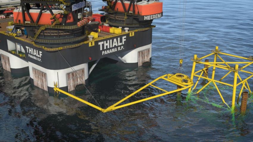
Noise mitigation for the construction of
increasingly large offshore wind turbines
Technical options for complying with noise limits
Sven Koschinski & Karin Lüdemann
Authors:
Dipl. Biol. Sven Koschinski Dipl. Biol. Karin Lüdemann
Meereszoologie Wissenschaftsbüro Hamburg
Kühlandweg 12 Hudtwalckerstr. 31a
24326 Nehmten 22299 Hamburg
sk@meereszoologie.de luedemann@wissensbuero-hh.de
Commissioned by the
Federal Agency for Nature Conservation
(Bundesamt für Naturschutz, BfN)
Technical supervision (BfN): Alexander Liebschner, Thomas Merck - FG II 5.3
March 2020
This report was supported by the Federal Agency for Nature Conservation. Responsibility for the content lies
solely with the authors. The owner reserves all rights. In particular, this report may only be quoted, reproduced
in whole or in part or made accessible to third parties with the consent of the client. The report reflects the views
and opinions of the authors, which are not necessarily those of the client.
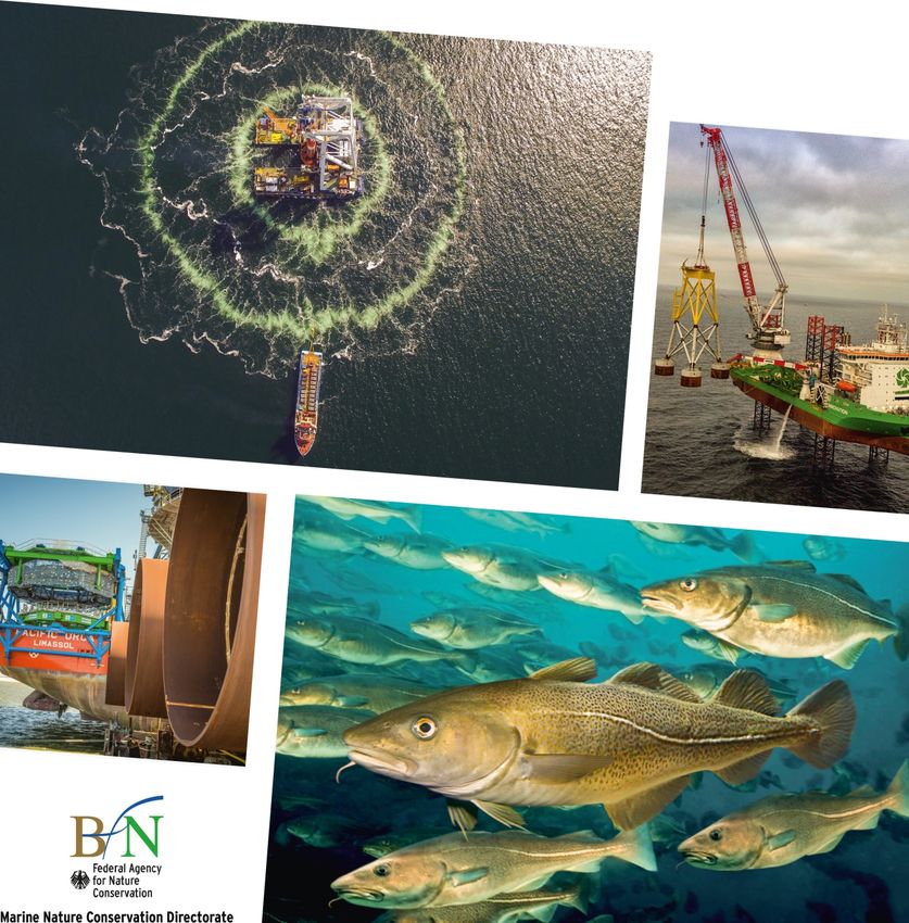
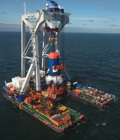
Photo copyright (title page): top left: Hydrotechnik Lübeck; top right: Ørsted; bottom left:
Vattenfall/photographer: Ulrich Wirrwa; bottom right: Photoshot/juniors@wildllife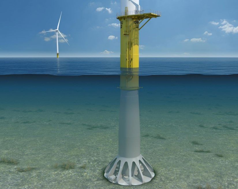
Table of Contents

1.    Introduction ..................................................................................................................... 4

2.    Big Bubble Curtain (BBC) .............................................................................................. 8

3.    Isolation Casings ...........................................................................................................10

4.    Hydro Sound Dampers ..................................................................................................12

5.    Dewatered Cofferdams..................................................................................................14

6.    Double Piles/Mandrel Piles ...........................................................................................16

7.    Pulse prolongation by adaptation of hydraulic hammers ........................................18

8.    BLUE Piling ....................................................................................................................20

9.    Vibropiling ......................................................................................................................22

10.   Drilled Foundations .......................................................................................................24

11.   Gravity Base Foundations ............................................................................................26

12.   Suction Bucket Jacket (SBJ) ........................................................................................28

13.   Mono Bucket Foundation .............................................................................................30

14.   Floating Wind Turbines .................................................................................................32

15.   Push-In and Helical Piles ..............................................................................................34

16.   Further noise mitigation measures and alternative foundation variants ...............35

17.   Conclusions ...................................................................................................................36

18.   References ......................................................................................................................37
Noise Mitigation Report                                                                         Introduction

    1. Introduction
Offshore wind energy is expected to make an important contribution in the context of transition to
carbon-free energy generation. In the past two decades offshore wind energy has reached its technical
maturity and the number of offshore windfarms and power generated has grown exponentially. The
power rating per offshore wind turbine has increased considerably, from 660 W (Offshore Wind Farm
(OWF) Bockstigen, Sweden – built in 1998) to 6 to 8.4 MW in OWFs currently being built (4C-Offshore,
2019). At the same time the sizes of monopiles and available pile driving equipment has increased
making it possible to use XXL monopiles for increasingly large turbine sizes and water depths. Recently
built monopile foundations have a diameter of 7 to 8 m and the steel industry is about to provide
monopiles of up to 12 m in diameter and 100 m in length for the upcoming generation of 12 to 14 MW
wind turbines and for greater water depths. Offshore construction of such large piles will have
implications for the noise radiated into the marine environment during impact pile driving (Bellmann
et al., 2018). Fig. 1 demonstrates a general interrelation of pile diameter and measured peak and sound
exposure levels. Major sound energy is emitted in the low frequency range of about 100-500 Hz
(Bellmann et al., 2015).

Fig. 1. Measured Peak Levels (LPeak) and broadband Sound Exposure Levels (SEL50) normalised to a distance of
750 m to the source during impact pile driving at various OWFs as a function of pile diameter (Bellmann et al.
2018).

Widespread adverse effects on marine organisms that are exposed to underwater noise have been
shown to occur both on a short timescale (acute effects) and on a long timescale (chronic effects). Fish
and invertebrate species depend on sound for vital functions. To date, around 100 fish and
invertebrate species have been shown to be impacted by noise from human activities. These impacts
include decreases in growth, body condition, feeding, productivity, abundance, immune competency
and nutrition, and catch rates. Underwater noise has the potential to damage ears and other sensory
organs (such as statocysts), cause developmental delays and malformations in their larvae, increased
stress, and death. In particular, piling noise has an impact on abundance, growth, body condition, anti-
predator defense, school coordination and cohesion, and cause masking, barotrauma injuries, stress
and indirect trophic (predator/prey) effects (Thomsen et al., 2006; Mueller-Blenkle et al., 2010; Perrow
et al., 2011; Casper et al., 2013; Bruintjes et al., 2016; Debusschere et al., 2016; Spiga et al., 2016;
Casper et al., 2017; Halvorsen et al., 2017; Herbert-Read et al., 2017; Kastelein et al., 2017; Mahanty
et al., 2017; Spiga et al., 2017). Impulsive noise, such as piling, as well as continuous noise have also
been shown to impact ecological services provided by invertebrates such as water filtration, sediment
                                                      4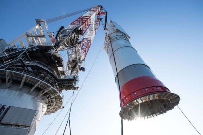
Noise Mitigation Report                                                                     Introduction

mixing, and bio-irrigation which is key to nutrient cycling (Roberts et al., 2015; Solan et al., 2016).
Management implications include the apparent inefficacy of ramp ups, intermittent sounds producing
slower behavioral recovery, and drilling likely being less impactful than piling, especially if periods of
rest between sessions are allowed (Neo et al., 2014; Neo et al., 2016). Impacts from particle motion,
through the seabed or water, also need to be assessed (Weilgart, 2018).
With respect to underwater noise effects (at both, individual and population level) a particularly well
investigated marine mammal species is the harbour porpoise. Impact pile driving has the potential to
scare harbour porpoises away at distances > 20 km (Tougaard et al., 2009; Dähne et al., 2013). Research
shows that noise mitigation measures can contribute much towards marine mammal conservation in
windfarm construction areas. By the use of noise mitigation measures, the zone of responsiveness of
harbour porpoises can be significantly decreased. At Dantysk wind farm (built in 2013 with bubble
curtains employed as a noise mitigation technique) the range of deterrence was reduced to 12 km and
responses lasted until 5 hours after cessation of piling. Elevated swimming speeds and increased
feeding activity after cessation of pile driving indicate that porpoises were probably not able to feed
during piling operations and the lost opportunities for feeding had to be compensated for (Dähne et
al., 2018). Since harbour porpoises have very high food requirements, this makes them especially
vulnerable to disturbance (Wisniewska et al., 2016). This predisposition can result in long term
energetic consequences of disturbance, even when using noise mitigation.
Besides noise mitigation measures, acoustic deterrents (such as seal scarers) are being used prior to
the start of piling in order to keep harbour porpoises out of the zone of hearing loss. However, the
range of deterrence by these devices may also result in similar effects as mitigated piling noise. This
has management implications with respect to specifications of scaring devices (Dähne et al., 2017;
Dähne et al., 2018). To assess possible population consequences it is furthermore necessary also to
take into account the observed behavioural reactions of porpoises to mitigated pile driving (using
various mitigation measures) because the type of mitigation system is critical for the frequency content
of the received noise.
Countries such as Germany, Belgium, the Netherlands, United Kingdom, Denmark, Japan, South Korea
and Taiwan have introduced legal restrictions for underwater noise to protect marine wildlife and thus
an increasing need to mitigate underwater noise arises. For example, in German waters a mandatory
threshold of 160 dB (SEL) and 190 dB (peak-to-peak) at a distance of 750 m during pile driving has been
established in 2008 for the protection of marine mammals. Today the implementation of technical
noise mitigation systems is a standard requirement at offshore construction sites. A reliable
compliance with the threshold is safeguarded by procedures including releases of tranches of 8-10
wind energy converters at a time and the obligation to deliver efficiency control reports based on in-
situ measurements (Zeiler, 2018).
Several technical noise mitigation systems have the potential to reduce noise emissions during impact
pile driving of offshore wind turbine foundations. Earlier reports have compiled information on such
technical noise mitigation methods but also on alternative low-noise foundations (Koschinski and
Lüdemann, 2011; 2013; OSPAR Commission, 2016). Due to the rapid and dynamic development of
offshore wind and noise mitigation, an update is worthwile.
Several parameters influence the resulting noise levels such as pile diameter, water depth, soil
structure and blow energy. The more energy is required to drive larger piles into the substrate, the less
likely it is that existing mitigation methods alone will be suited to meet current noise standards in the
future. For this reason the Geman Federal Agency for Nature Conservation organised an international
                                                     5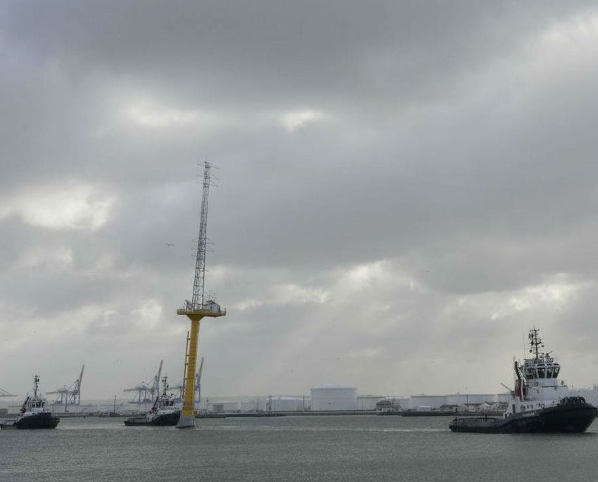
Noise Mitigation Report                                                                    Introduction

conference on Noise mitigation for the construction of increasingly large offshore wind turbines -
Technical options for complying with noise limits which took place in Berlin from November 22 to 23,
2018.
The aim of the conference and this report is to revisit the issue of underwater noise mitigation in the
light of an anticipated further increase in turbine size. We describe and analyse the effectiveness of
existing noise mitigation measures and readyness for use with increasingly large monopiles. Monopiles
have by far the most extensive experience in the construction of offshore wind farms. Thus, they form
the basis for comparative considerations. More experience is needed and explicitly desired with
foundation types other than the monopile in order to make them a reliable, safe and economically
viable alternative to the standard monopile and provide a benefit for the marine environment. This
report gives a general view on the suitablity of existing noise mitigation methods for the piling of so-
called “XXL monopiles” and alternative low-noise foundations for increasingly large turbines.
The noise mitigation systems are based on various principles. Here we distinguish between primary
and secondary noise mitigation. Whereas primary noise mitigation counteracts the generation of
noise directly at the source, secondary noise mitigation reduces the radiation of noise by placing noise
barriers at some distance from the pile. During piling, about 1 % of the impact energy on the pile is
transformed into unwanted underwater noise by oscillating circumferential expansion along the length
of the pile caused by the hammer strike (Elmer et al., 2012). Some of this noise radiates through the
water column whereas another part radiates through the water saturated ground in a specific way and
may again couple to the water column at some distance (Dahl and Reinhall, 2013). This effect may limit
secondary noise mitigation in their effectiveness if not explicitely addressed by the method.
Reliable and accurate prediction models to enable a prognosis of the noise levels prior to construction
are available to assess the noise emission and configure possible mitigation measures. State of the art
numerical prediction models have proven to be especially capable for this task, as they allow for a
detailed consideration of the applied hammer technology, the pile geometry, possible noise mitigation
measures as well as the specific propagation conditions in both water column and soil (Lippert, 2018).
In addition to noise mitigation methods, several alternative low-noise foundation types exist or are
under development. Using these methods, wind turbines can be founded without impact pile driving
and therefore less underwater noise generation is expected. Ideally, no additional noise mitigation will
be required.
During the installation, continuous rather than impulsive sound is emitted at varying levels and
including various frequencies. Due to major differences in acoustic properties the impact of continuous
sound of a given level cannot be directly compared to the impact of impulsive sound of the same level.
Thus, possible effects, especially with respect to disturbance must be addressed in future scientific
studies and the regulatory framework.
In each of the chapters on noise mitigation measures, a technical description and a brief description
of the underlying noise mitigation principle is given. Further, the experience from tests or projects and
the noise reduction are being described. The development status and the suitability for XXL monopiles
is also given. In the chapters on low-noise foundations, the scalability for increasingly large wind
turbines is briefly analysed on the basis of information presented at the conference.
The noise reduction achieved is given as the ΔSEL, i. e., the difference between sound exposure level
normalised to a distance of 750 m of piling with and without noise mitigation. Depending on the
mitigation method, it may not be possible to measure these at the same pile and thus, in some cases
                                                   6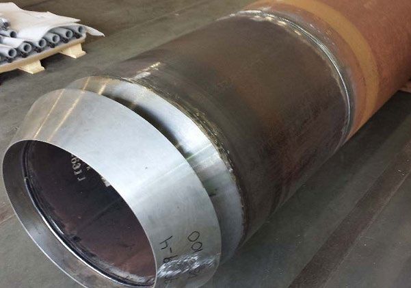
Noise Mitigation Report                                                                     Introduction

it is given in comparison to a similar reference pile. The difference in peak sound pressure level is
usually larger than the ΔSEL, but it is a very sensitive metric with a (large uncertainty). If a number of
noise mitigation systems are used in combination, the combined ΔSEL is smaller than the sum of each
separate noise mitigation measures. Decibel values for noise reduction are project and site specific
and thus cannot be guaranteed.
The compilation of secondary noise mitigation methods starts with three methods which already can
be considered state of the art under conditions typically found in the North Sea: big bubble curtains,
isolation casings and Hydro Sound Dampers. The remainders are not arranged according to their
relevance or state of development. Secondary noise mitigation methods are followed by primary noise
mitigation methods and alternative low noise foundations or noise-free foundations. The boundary
between the two latter is not sharp as the biological significance of sounds generated during their
deployment has not been well studied yet.

                                                    7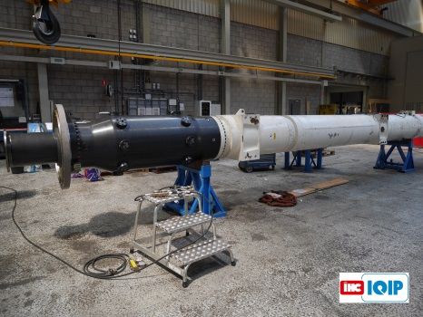
Noise Mitigation Report                                                           Secondary Noise Mitigation

    2. Big Bubble Curtain (BBC)
Type of Noise Reduction: Secondary
Noise Reduction Principle: Reflection, scattering and absorption (frequency
dependent)
Combination with: E.g., single, double, triple application, isolation casing, HydroSound
Dampers, reduced blow energy, prolonging pulse duration
Noise Reduction: Single: up to 15 dBSEL (depth: 25m), double: up to 18 dBSEL (40 m)
Development Status: State of the art (up to ~40 m water depth, ~8 m pile diameter)

5.1 Technical Description
                                                                                           © Hydrotechnik Lübeck
Technical Description
A BBC is formed by bubbles freely rising from a weighted nozzle pipe on the sea floor at larger distance
to a monopile, tripod or jacket foundation. Its design must ensure that the BBC is fully closed around
the entire structure to avoid noise leakage. In order to ensure a uniform pressure distribution, the
diameter of the nozzle opening increases from the feed points. A pipe-laying vessel with a driven winch
fitted with hydraulic or pneumatic brakes aids the circular or eliptic pipe installation. Compressors
located on the vessel are used to feed air into the nozzle pipe. Operational depth is limited. The
optimum pressure difference between pressure inside the hose and hydrostatic pressure is 3 to 4 bar
(Nehls et al., 2016). Further, sufficient air volume stream must be provided. At greater depth an
increased air volume stream (and thus more compressors) is needed due to compressibility of air
bubbles. During rising their volume increases and bubbles split. Bubble drift by currents requires the
use of an elliptical nozzle pipe. Principal mechanisms responsible for the noise reduction depend on
the frequency content of the radiated sound. A broad range of frequencies is attenuated by the
impedance mismatch between water and the bubbly layer (water + air). This causes wave reflections
and scattering at the interface between the two media. At higher frequencies, acoustic stimulation of
bubbles close to their resonance frequency additionally reduces the noise by means of absorption
(Tsouvalas and Metrikine, 2016). In contrast to noise mitigation systems close to the pile, seismic
waves such as bottom-generated Mach waves re-entering the water column (Nedwell and Howell,
2004; Stokes et al., 2010; Reinhall and Dahl, 2011; Dahl and Reinhall, 2013) can also be mitigated by
large diameters of the BBC. This increases its overall noise reduction potential which otherwise would
be limited due to recoupling of seismic waves.
Experience
Big bubble curtains have been applied as an effective noise mitigation technique at >700 piles in the
North and Baltic Seas in single or double applicaton (Bellmann et al. 2018). The installation process can
be adapted to construction activities. Two complete redundant bubble curtain systems on the pipe-
laying vessel can be installed revolvingly. Installation can be done before or after the installation vessel
is in position and thus time delays can be kept low. Tractive forces causing material fatigue can deform
the nozzles requiring redrilling to keep noise reduction constant between locations (Nehls et al., 2016).
Little Bubble Curtains (with bubbly water close to the pile) have been applied experimentally in the
German test field alpha ventus and the OWF BARD Offshore 1 (Betke and Matuschek, 2010; ITAP, 2013)
but not further developed for commercial use.

                                                       8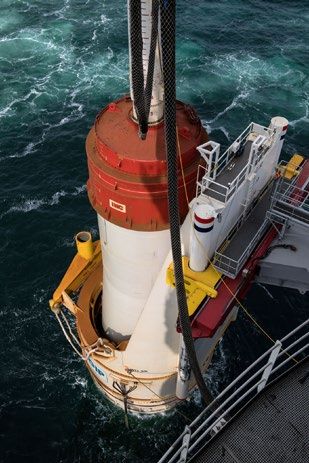
Noise Mitigation Report                                                      Secondary Noise Mitigation

Noise Mitigation
Over 2,000 measured data sets at distances between 50 m and 5,000 m to piles are available, inside
and outside the BBC, as well as pressure and air flow measurements inside the nozzle pipe. As a single
application with an air volume stream of 0.3 m3/min*m, the noise reduction (ΔSEL) was in the range
of 11-15 dB at 25 m water depth, decreasing with depth (8-14 dB at ~30 m and 7-11 dB at ~ 40 m). A
double BBC increased the noise reduction by an additional ~3 dB. With a larger air volume stream (>
0.5 m3/min*m) required for deeper water, a maximum ΔSEL of 18 dB was measured at ~ 40 m and a
mean ΔSEL of 15-16 dB at >40 m. However, this value is based on few measurements only. Decreased
noise reduction has been found in cases of strong currents or sub-optimal configuration (Bellmann et
al. 2018). This observation demonstrates that project specific configurations are necessary. In double
applications the distance between nozzle pipes must be large enough to allow for the formation of
separate bubble curtains (Fig. 2). Best results were achieved with a distance between pipes larger than
the water depth (Nehls et al., 2016). Frequencies best attenuated are those above ~1 kHz, however,
differences between individual BBCs have been measured (Dähne et al., 2017) (Fig. 2). These product-
specific mitigation properties can be particularly important with respect to harbour porpoise
disturbance which is strongest at >1 kHz (Dyndo et al., 2015).
Development Status
The BBC is the best-tested and proven noise mitigation technique for OWF foundations such as jackets,
tripods or monopiles. Today’s BBC systems are robust and the entire handling of the BBC can be done
independently of the jack-up rig. All of the currently available big bubble curtain systems are reusable.
Major costs are generated by the supply of bubble curtains with compressed air. Up to a water depth
of ~30 m the BBC can be considered state of the art because, with an optimised system, a ΔSEL of 15
dB (single) to 18 dB (double) can be reliably achieved. Due to decreasing effectiveness in deeper
waters, a ΔSEL of 15 dB can be challenging and a project specific adaptation/optimization is required
(Bellmann et al., 2018). BBCs will have to be customised for each project.
Suitability for XXL monopiles
Larger wind turbines may not only be installed using larger monopiles but also at increasing water
depths, which both can be challenging. Double or even triple BBCs offer options for larger monopiles.
The BBC can further be combined with other noise mitigation measures to meet legal standards at
larger water depths or with larger pile diameters which may emit higher noise levels (Bellmann et al.,
2018). To increase the noise reduction, BBCs have so far been combined with additional noise
mitigation by isolation casings (Ch. 3), HSD (Ch. 4) or reduced blow energy (Ch. 16).

Fig. 2. Double BBC combined with HSD at OWF Veja Mate (left, © Hydrotechnik Lübeck GmbH), recordings of
pile driving at OWF DanTysk using 0 to 2 BBCs at distances between 2.4 and 4.5 km and power spectral
densities (Dähne et al., 2017). BBC1: System Weyres, air volume stream 0.11 m³/m min-1, BBC2: System
Hydrotechnik Lübeck, air volume stream 0.43-0.52 m³/m min-1.

                                                    9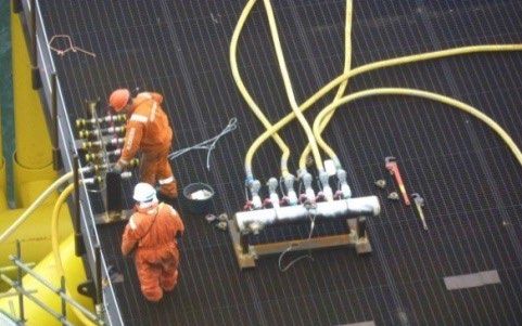
Noise Mitigation Report                                                        Secondary Noise Mitigation

    3. Isolation Casings
Type of Noise Reduction: Secondary
Noise Reduction Principle: Shielding, reflection
Combination with: Additional built-in features, (double) BBC, reduced blow energy,
prolonging pulse duration
Noise Reduction: 13-16 dBSEL (depth:
Noise Mitigation Report Secondary Noise Mitigation
An additional feature which allows for further reducing the noise is the reduction of blow energy (“HiLo
piling”). In this piling method, the blow rate is increased and the energy per strike reduced. A reduction
in blow energy by 50 % would achieve further 2.5 dB in ΔSEL (Bellmann et al., 2018). A disadvantage is
that the number of strikes is increased, and probably also the duration per monopile installation.
Development Status
The Integrated Monopile Installer with NMS is a proven technology which has shown its ability to
substantially reduce piling noise. In over 450 successful applications of the NMS, its suitability for
offshore applications, manageability, flexibility in construction logistics and safety has been
demonstrated. It is state of the art up to a water depth of about 40 m and a pile diameter up to about
8 m. It has been proven a robust and reliable system which has no impact on installation times. It is
reusable and cost-effective.
Suitability for XXL monopiles
In contrast to a BBC, noise mitigation by an NMS is largely independent of water depth (Bellmann et
al. 2018). To increase the noise reduction, NMS have so far been combined with additional noise
mitigation by (double) BBCs (Ch. 2), or reduced blow energy (Ch. 16). Prolonging the pulse duration is
another possibility to further reduce the noise level (Ch. 7). Early experiments using this principle
reached a ΔSEL of up to 7 dB, but struggled with the durability of pile cushion material such as
steelwire, wood, nylon and Micarta (Laughlin, 2006; Elmer et al., 2007a). The company IHC IQIP
currently develops a method using water as a pile cushion called “PULSE”. This has been successful
with an S-90 hammer and a test pile (Ø 1m) and resulted in a ΔSEL of 6 – 9 dB and also less material
fatigue compared to a reference pile. Upscaling for XXL monopiles would require an additional weight
of 108 t and height of the hammer of 3.2 m (van Vessem and Jung, 2018). With increasing pile lengths
the crane may reach its limit and the installation process may need some adaptations: depending on
the availability of installation methods the NMS may have to be put over the pile (such as already done
in the OWF Riffgat) instead of inserting piles into the NMS from the top (current method).
Fig. 3. Monipile installation at the OWF Borkum Riffgrund 1 using the Integrated Monopile Installer with NMS
(left, © Ørsted). Frequency spectra (SEL third-octave band level) of ramming noise with and without NMS at
OWF Borkum Riffgrund 1, measured 750 m from the pile given as percentiles (right, Gündert et al. 2015).
11Noise Mitigation Report Secondary Noise Mitigation
4. Hydro Sound Dampers
Type of Noise Reduction: Secondary
Noise Reduction Principle: Scattering and absorption by resonators, reflection,
dissipation and material damping (frequency tuning possible)
Combination with: BBC, reduced blow energy, prolonging pulse duration
Noise Reduction: 10-13 dBSEL (depth: 340 piles in various commercial offshore windfarms at water
depths up to 45m and pile diameters up to 8 m with a very low rate of malefunctions (20 dB (Bruns et al., 2014). In combination with a double BBC (Ch. 2) a ΔSEL of 18-24 dB has been
achieved with a pile diameter of 7.8 m at a water depth of 40 m (Elmer, 2018). HSD can be adjusted to
unwanted ground coupling effects (concept in Fig. 4).
Development Status
Hydro Sound Dampers have often been used and tested in piling applications. HSD are available on the
market and are considered state of the art noise mitigation with pile diameters of up to 8 m and a
water depth ofNoise Mitigation Report Secondary Noise Mitigation
Other than in BBC (Ch. 2), no depth dependence of efficiency has been found (Bellmann et al., 2018).
HSD systems will have to be customised for each project. The number of HSD elements per area must
be weighed against desirable noise reduction and buoyancy.
Suitability for XXL monopiles
Currently available HSD net baskets can be used with monopile diameters up to 10 m. For larger
diameters, specific adaptations are needed. There are already concepts for HSD nets to be used with
larger monopile diameters at increasing water depth. Larger HSD elements for depths up to 50 m have
already been developed. Increasing the water depth from 40 to 50 m would result in up to 35 % more
volume of HSD nets and 35 % more weight of HSD baskets. Current crane capacity would not allow for
inserting very long monopiles from the top. An openable HSD basket already allows inserting
monopiles of unlimited length from the side. In 2017, two monopiles (Ø 7.5 m) per day have been
installed in the OWP Arkona in the German Baltic Sea using the openable HSD-System for XXL
monopiles (Elmer, 2018). To increase the noise reduction, HSD can be combined with a BBC (Ch. 2),
prolonging pulse duration (Ch. 7) or a reduced impact energy (Ch. 16).
Fig. 4. HSD net for a water depth of 40 m with larger HSD elements on the bottom (due to compressibility with
hydrostatic pressure (left). HSD basket below pile frame (center, top). Concept of a HSD basket covering the sea
floor close to the pile in order to mitigate also ground coupling effects (center, bottom). Concept of an
openable HSD basket for very long monopiles to be inserted sideways (right). © K.-H. Elmer, OffNoise
Solutions.
13Noise Mitigation Report Secondary Noise Mitigation
5. Dewatered Cofferdams
Type of Noise Reduction: Secondary
Noise Reduction Principle: Decoupling noise from the water column
Combination with: BBC, HSD, reduced blow energy, prolonging pulse duration
Noise Reduction: Up to 23 dBSEL (depth: 15 m)
Development Status: Monopile full scale prototype tested offshore in 2011,
state of the art in substations
©K.E. Thomsen
Technical Description
A cofferdam is a steel tube surrounding the pile from seabed to surface decoupling pile vibrations from
water by means of a dewatered annular gap and thus effectively reducing sound energy transfer (Fig.
6). The air fully separates the pile surface from sea water. The pile is centred with a guidance system
(McKenzie Maxon, 2012; Thomsen, 2012). The cofferdam needs to be sealed effectively at the bottom
and dewatered by pumps (Thomsen, 2012) or overpressure (Frühling et al., 2011; Heerema Marine
Contractors, 2013). A cofferdam which has been used for offshore platforms is based on the principle
of Pile-in-Pipe Piling. The noise mitigation system is integrated into the base frame foundation as
protective pile sleeves reaching beyond sea level (Fig. 5). In this particular case, piling occurred only
above sea level (Frühling et al. 2011).
Experience
Offshore wind farm applications of cofferdams have been used for jacket installations of platforms
(BorWin beta and DolWin alpha converter platforms at a depths ≤40 m and HelWin alpha cable access
tower and piles with a Ø up to 3.2 m) (Wijk, 2013). For DolWin alpha platform the jacket leg itself was
dewatered using air inlets on the top and outlets and seals at the bottom of the jacket leg (Fig. 5, top).
Due to special underwater jacket configuration for BorWin beta platform an external cofferdam was
used as an extension on top of the pile sleeve which did not extend above the water (Fig. 5, bottom).
In 2011 and 2012, full scale prototype monopiles have been installed using cofferdams in Aarhus Bight
(pile length 36 m, pile Ø 2.13 m, cofferdam Ø 2.5 m, water depth 15 m,) and at the OWF Anholt (pile
Ø 5.9 m, cofferdam Ø 6.3 m, water depth 19 m) (McKenzie Maxon, 2012; Thomsen, 2012). However,
the Anholt pilot test was not successful because protrusions of the pile which were not designed for
use with a cofferdam resulted in an inappropriate cofferdam design with large seals at the bottom. As
a consequence of pile positioning off the center, the seal failed and the annular gap was not completely
dewatered.
Noise Mitigation
The measurements at the Aarhus Bight test pile confirmed a high noise reduction potential of
cofferdams (ΔSEL = 23 dB) which however is compromised in the case of direct contact between the
pile and the cofferdam (ΔSEL = 13 dB) (McKenzie Maxon, 2012). It seems that the failure of the seal,
which could have been prevented by adaptation of the pile design to the cofferdam, disrupted the
industry's confidence in this noise mitigation system. To the knowledge of the authors there are
currently no cofferdam applications in offshore windfarm construction.
14Noise Mitigation Report Secondary Noise Mitigation
Suitability for XXL monopiles
Foundations using cofferdams for noise mitigation are scalable. However, water pressure acts against
the seal from the bottom and thus their size and the hydrostatic pressure are limiting factors.
If used with larger monopiles it is of particular importance that the engineering of the piles and their
corresponding cofferdam must be matched closely. Jacket foundations provide another option for
large wind turbines to avoid technical challenges with large monopiles. A concept study for a jackets
foundation for water depths up to 30 m with pile sleeves extending above the water to be used as
cofferdams similar to proven platform technology (pile-in-pipe-piling) is available (Frühling et al.,
2011).
Fig. 5. Schematic drawing (top left) and application of jacket legs extending above the water surface and thus
acting as cofferdams at Dolwin alpha (top middle); air hoses for dewatering the pile sleeve (top right) at DolWin
alpha; Installation of a cofferdam extension on top of the pile sleeve (bottom left) and piling through the
complete cofferdam at BorWin beta (bottom right) © TenneT
Fig. 6. Cofferdam application with monopile (left: Aarhus Bight, right: OWF Anholt) ©K.E. Thomsen
15Noise Mitigation Report Secondary Noise Mitigation
6. Double Piles/Mandrel Piles
Type of Noise Reduction: Secondary
Noise Reduction Principle: Decoupling of noise radiation in water and sediment
Combination with: E.g., BBC, HSD, reduced blow energy, prolonging pulse duration
Noise Reduction: 16 dBSEL (depth: 10 m)
Development Status: Two full-scale tests successfully performed nearshore
© J. Laughlin, WSDOT
Technical Description
The double pile consists of two concentric steel piles flexibly connected by a special driving shoe,
assuring that there would be no pile-to-pile contact during driving. This allows for an air gap between
the two tubes. The inner pile is equipped with a reinforced toe that serves as a sealing to prevent water
intrusion. A hydraulic impact hammer strikes the inner pile only which pulls the tethered outer pile
along into the sediment. The noise mitigation principle is the decoupling of sound from the water and
also the substrate. Depending on the pile design, the inner tube (mandrel) can be removed after the
pile has reached its final penetration depth. The mandrel can be re-used repeatedly (Reinhall et al.,
2015).
Experience
Two full-scale tests of various configurations of double-walled piles with an outer diameter of 0.8 m
were performed at different locations in Puget Sound, Washington at 10 m and 8 m water depth. The
inner pile was driven using a single acting impact hammer with a maximum energy of 154 kJ, resp. 275
kJ. The first test was performed in soft sediment whereas the substrate at the second test site consisted
of dense glacial deposits.
Noise Mitigation
The primary source of underwater noise from pile driving is associated with circumferential expansion
along the length of the pile caused by the hammer strike. The air gap and the flexible coupling of the
double pile prevent the radial expansion wave from interacting with the water and the sediment. Other
than the cofferdam (Ch. 5), the double pile also addresses the propagation of Mach sound waves
directly from the sediment (Reinhall and Dahl, 2011). These could otherwise bypass other secondary
noise mitigation systems deployed close to the pile which shield the noise radiation in the water
column only. In the first full-scale field test, the ΔSEL (measured at 500 m distance) was 16 dB (Reinhall
et al., 2015). A second field test reveiled a lower noise reduction due to unexpected steel-to-steel
contact between double pile and a template making the interpretation difficult (Reinhall et al., 2016).
Development Status
After finite element simulation and prototype testing, in 2014 and 2015 two full-scale test piles were
successfully driven at two sites with different soil types in nearshore environments. In the second test
it was shown that the pile capacity of the novel piles was comparable to that of a control pile with the
same outer diameter (Reinhall et al., 2015; Reinhall et al., 2016).
16Noise Mitigation Report Secondary Noise Mitigation
Suitability for XXL monopiles
So far, only piles with small diameters (0.8 m) were built. The scalability remains to be shown in further
applications.
Fig. 7. Double pile stem with driving shoe (left), SEL frequency distribution (middle) during piling of control pile
(red) and double pile configurations (green and blue), ( Reinhall et al., 2015). Schematic of flexible coupling to
connect outer and inner pile in the driving shoe (right, Reinhall et al., 2016).
17Noise Mitigation Report Primary Noise Mitigation
7. Pulse prolongation by adaptation of hydraulic hammers
Type of Noise Reduction: Primary
Noise Reduction Principle: Prolongation of the pulse duration
Combination with: All secondary noise mitigation methods
Noise Reduction: ~9 dBSEL (as suggested by numerical prediction model)
Development Status: Concept, under development
Early experiments making use of pulse prolongation were made with small piles using pile cushions of
a steel wire, plywood, nylon and Micarta between piston and pile. The principle of this method consists
of reducing the driving force while acting on the pile over a longer period. Application of pile cushions
reached ΔSELs between 7 dB for steel wire and 26 dB for wood. However, these experiments struggled
with the durability of pile cushion material and safety issues (Laughlin, 2006; Elmer et al., 2007b).
The company IHC IQIP currently develops an adjustable cushioning method using a liquid between
pistons to reduce the generation of noise. This addon for a standard hammer (called PULSE, Piling
Under Limited Stress Equivalent) requires 4 % more energy. Installed in an IHC S90 hammer (PULSE
weight 1 t, height 1 m) an additional noise reduction (ΔSEL) of 6-9 dB has been measured. A 10 %
efficiency improvement in pile driving time and reduced material fatigue could be achieved. It is
currently upscaled for use with the largest hammer (S4000 hammer) expected to be ready by the end
of the year 2019. The expected noise reduction (ΔSEL) is 4-6 dB. Dimensions of the PULSE system for
this hammer are an additional 108 t in weight and 3.2 m in length (van Vessem and Jung, 2018).
The company MENCK is developing a noise reduction unit (MNRU) using a number of metal blocks
placed between the ram weight which is accelerated by the hydraulic fluid and the anvil which
transfers the impact energy to the pile (Fig. 8) (Steinhagen, 2019). Damping the contact force between
anvil and pile using this method also reduces material fatigue of the pile. The MNRU can simply be
added to existing standard hydraulic hammers. By the use of the MNRU, the efficiency of the hammer
is slightly reduced (in a model from 97 to 84 %). By the use of a sufficient hammer size, it can be
safeguarded that the pile is still driveable. For a 6.5 m monopile and a 3500 kJ hammer a numerical
model predicted a ΔSEL of 9 dB and a Δpeak of 11 dB. The duration of the energy transfer into the pile
during a pile strike is almost doubled by the MNRU and noise emissions are shifted to lower
frequencies (Steinhagen, 2019).
18Noise Mitigation Report Primary Noise Mitigation
Fig. 8. View of a standard hydraulic impact hammer and a modified hammer (right) with a MENCK Noise
Reduction Unit (MNRU) added between ram weight and anvil (left, © MENCK) and IHC S-90 hammer with
added PULSE system in black housing (middle) and cross-sectional view (right, © IHC IQIP).
19Noise Mitigation Report Primary Noise Mitigation
8. BLUE Piling
Type of Noise Reduction: Primary
Noise Reduction Principle: Prolongation of the pulse duration
Combination with: All secondary noise mitigation methods
Noise Reduction: 19-24 dBSEL (depth: 22.4 m)
Development Status: Full scale prototype successfully tested under offshore
conditions, improvements on technology currently studied and implementation
© Fistuca BV
Technical Description
Another method using the principle of pulse prolongation (Ch. 7) is BLUE piling. The innovative BLUE
25M hammer uses a large water column to generate the driving force. Sea water inside a steel tube
closed at the bottom is pushed upwards and allowed to fall on the pile. The resulting pulse drives the
pile in the ground. This cycle is repeated until the pile reaches its desired depth. The acceleration is
much lower compared to a hydraulic impact hammer (Winkes, 2018). During the piling process
seawater is added, thereby gradually increasing the blow energy as needed. The principle of primary
noise reduction is the prolongation of the pulse duration. In BLUE piling, the pulse duration is increased
by a factor of up to 20 compared to a hydraulic hammer. When the impact energy is distributed over
a longer period, the maximum impact force and thus the amplitude of the lateral extension of the pile
is reduced. At the same time the spectrum emitted is shifted to lower frequencies because the
oscillation period of compression waves in the pile is prolonged (Fig. 9). The reduced propagation
velocity of the lateral extension directly decreases the sound emission (Elmer et al., 2007a; Elmer et
al., 2007b). Lower pile vibrations also reduce the pressure amplitude in the seismic component of
radiated noise (Reinhall and Dahl, 2010; Dahl and Reinhall, 2013). The gradual increase in force also
reduces material fatigue by lowering the tension stress on the pile. No stiffeners are needed on the
internal platform and the piles can be driven fully assembled with all appendages.
Experience
BLUE piling uses a completely different method for pulse prolongation than the other techniques of
pulse prolongation described in Ch. 7. A number of nearshore and offshore tests with various hammer
sizes were conducted. In the most recent test in summer 2018 the function of the BLUE 25M hammer
prototype could be proven. The blows were about 100 ms long (compared to about 8 ms of a hydraulic
hammer). Additional work is still needed to increase the capacity and reliability. Further testing is being
planned.
20Noise Mitigation Report Primary Noise Mitigation
Noise Mitigation
Direct comparisons between conventional and BLUE piling methods are difficult as this would require
switching the equipment at the same pile. An offhore test with a pile (Ø 6.5 m), reveiled the best noise
reduction in third octave level bands between 100 Hz and 4 kHz compared to a reference pile driven
conventionally in the same waters (Fig. 9). The SEL in these third octave band levels were up to 24 dB
lower. With respect to broadband values (10 Hz-20 kHz) ΔSEL was 19-24 dB. In >95 % of all blows, the
noise level measured at a distance of 750 m was below 160 dBSEL.
Development Status
In summer 2018, a full scale prototype of the BLUE 25M has been tested under offshore conditions.
Before it is ready for the market, improvements and additional tests are needed (Winkes, 2018).
Suitability for XXL monopiles
According to the manufacturer, the BLUE 25M hammer is already capable of driving the largest piles
as they deliver over six times more energy than the largest available hydraulic hammers. Its rated
maximum energy is 25 MJ. It still remains to be shown whether the legal noise standards can be met
without additional external noise mitigation methods and how noise reduction changes with increasing
depth. However, since BLUE piling is a primary noise mitigation method, it would be promising to be
combined with secondary noise mitigation methods such as the BBC (Ch. 2) , HSD (Ch. 4) or isolation
casings (Ch. 3) to reach very high ΔSELs in future applications.
Fig. 9. Draining of seawater from BLUE 25M hammer upon completion of piling operation (left). Frequency
spectrum of BLUE piling compared to impact piling at two reference piles (right, note different dimensions:
BLUE Piling test: Ø6.5 m, water depth 22 m; reference Gemini OWF: Ø 6.6 m, water depth 30 m; reference Q7
OWF: Ø 4 m, water depth 19-24 m), © Fistuca BV.
21Noise Mitigation Report Primary Noise Mitigation
9. Vibropiling
Type of Noise Reduction: Primary
Noise Reduction Principle: Alternative piling method using low frequency oscillations
Noise Reduction: 10-20 dBLeq, 30s (depth:Noise Mitigation Report Primary Noise Mitigation noise emissions varied considerably (Elmer et al., 2007a; Betke and Matuschek, 2010; Kringelum, 2013). Some noise peaks resulting from a rattling sound created by loose connections of the vibrohead have been reported (Meyer, 2018). When the penetration of the pile slows down towards the end of vibropiling or in cohesive soils, harmonics at higher frequencies up to ~10 kHz or increasing sound levels (
Noise Mitigation Report                                                        Alternative Low-Noise Foundation

    10. Drilled Foundations
Type of Noise Reduction: Primary

Noise Reduction Principle: Alternative low-noise foundation

Development Status: State of the art e. g., for open hole drilling in hard substrate and
drive-drill-drive (relief drilling inside impact driven piles). Successful full-scale onshore
test of drilling/mixing technology for grouting jacket pinpiles in sandy sediments.
Vertical Shaft sinking Machine Drilling has been tested onshore.
Technical Description
                                                                                                © BAUER Spezialtiefbau GmbH
Various equipment are currently in use in diverse offshore drilling applications such as drilling in hard
substrates (bedrock, sandstone, limestone or mixed layers), relief drilling inside a pile when
resistance is met and impact piling ceases, or even drilling and installing piles in sandy sediments.
Hard substrates cannot be penetrated by impact piling. Several drilling methods are available. Fugro
Seacore uses a drilling tool extension (underreamer) underneath the pile which creates an overcut
and allows drilling exactly the pile diameter. Additional vertical thrust can be exerted on the pile
using hydraulic forces to allow for better penetration (Koschinski and Lüdemann, 2013). An
underwater drill rig Bauer BSD 3000 for water depths > 60 m and for drilling Ø 2 m jacket pinpiles
into rocky subsoils withstands strong currents. A recoverable conductor casing in a template ensures
stability during drilling and grouting the pile into the borehole which has a slightly larger diameter
than the pile (Scheller, 2018). The Drive-Drill-Drive method combines impact piling or vibropiling
with drilling. When resistance is met, the material inside the pile is drilled out. The Dive Drill is
suitable for various soil conditions. A temporary casing is installed by means of a casing oscillator
which enables penetration of the casing into the borehole which is drilled using an underreamer.
After drilling, the pile is inserted, grouted and the temporary casing recovered. Due to limited
diameters of drills they are applicable for e.g., pre-piled jackets. In sandy sediments, it is required
that the bearing capacity is increased by mixing the loosened soil with cement slurry which is then
pushed out into the anulus and grouts the pile in place. This is enabled by a specific drilling method,
the MIDOS (Mixed Drilled Offshore Steel) pile system: An extendable drilling and mixing tool is
inserted in a structural casing used as e. g., a pinpile for prepiled jackets. This method is usually
applied with 30 to 45 m long and Ø 2 m to 2.5 m piles with a ~0.4 m larger tip to create an anulus.
Experience
Vertical offshore drilling is frequently being used in seabeds not driveable by impact piling. Due to low
noise and vibration, drilling is increasingly used for environmental reasons. Commissioned in 1998, the
Swedish OWF Bockstigen was the first project with drilled monopiles in limestone. Its five 550 kW
turbines have been repowered in 2018 and the towers maintained (www.4Coffshore.com). Since then,
experience has been gained in various projects using diverse types of drilling equipment. Relief drilling
(Drive-Drill-Drive) has been applied at the OWFs Beatrice, North Hoyle, Gunfleet Sands and Teeside
installed on seabeds with mixed layers of sand, boulder clay and sand stone with pile diameters up to
4.7 m. BSD 3000 has been successfully used for the first time for the foundation of a tidal turbine off
the Scottish coast in bedrock at a depth of 37 m in 2011 (Scheller, 2018). In a field test in the Persian
Gulf, the capacity of the MIDOS Pile was seen to perform well (GDG, 2019).

                                                          24
Noise Mitigation Report Alternative Low-Noise Foundation
Noise Impact
Underwater drilling noise emissions depend, i.a. on the type of equipment and soil. Noise emissions
are from drill head, crusher box, casing oscillator, machines, air lift or pumps. Sound pressure levels of
underwater bedrock drilling with the BSD 3000 measured at 100 to 500 m distance were between 120
and 140 dB (Leq). Back-calculations reveiled a best fit source level of 167.8 dB (1 s integration). A similar
level was calculated based on measurements of structure- and water-borne sound during drilling of a
Herrenknecht Vertical shaft Sinking Machine (VSM) in the underground of Naples (Ø 5 m, 25 m below
groundwater level). Based on these data the potential noise emissions in an offshore application were
predicted as 160 dB (Leq) at 1 m or 117 dB at 750 m (Koschinski and Lüdemann, 2013). Drilling
generates continuous noise whose impact on the marine environment is not directly comparable to
that of impulsive noise (Southall et al., 2007) and thus needs to be investigated.
Development Status
There are two technologies currently available for the installation of drilled and grouted piles: (1) Dive
Drill with casing oscillator in which the borehole is always supported by a temporary casing, and (2)
Top Drill with sacrificial casing in loose material on top of the rock or open hole drilling in rock. Relief
drilling can be done inside Ø 7 m monopiles. The MIDOS Pile designed for embedding Ø 2.5 m jacket
pinpiles in sand was successfully tested in a full-scale test onshore. Herrenknecht Offshore Foundation
Drilling with VSM, a hydraulically controlled telescopic boom with rotary grinder drilling inside and
underneath a monopile, has been tested in a large-scale onshore experiment (two drilled monopiles
at scale 1:8) in 2012 (OSPAR Commission, 2016). The design is fully developed and awaits the next step
to a full-scale pilot project (B. Jung, Herrenknecht, pers. comm.). Van Oord’s (formerly Ballast Nedam’s)
concrete drilled monopiles (OSPAR Commission, 2016) are at concept stage.
Suitability for XXL wind turbines
Market available drilling technologies for application in sand which is the prevailing condition in the
North Sea (e.g., MIDOS Pile) are currently only suited for jacket pinpiles. Jackets are scalable for larger
turbines. Offshore Foundation Drilling with VSM is currently a concept for Ø 10 m monopiles and is
scalable for even larger monopiles. Scalability and noise reduction potential may in future outweigh
the disadvantage of likely longer installation times. The Fugro Seacore leader leg pile handling system
enables vertical drilling for large monopiles without the use of cranes. The system consists of two
vertical leader legs with a gripping and hydraulic lifting unit (OSPAR Commission, 2016).
Fig. 11. MIDOS pile with drilling and mixing tool inside the structural pile (left, © BAUER Spezialtiefbau GmbH).
Noise measurements of BSD 3000 drilling noise in rock (right, Scheller, 2018).
25Noise Mitigation Report Alternative Low-Noise Foundation
11. Gravity Base Foundations
Type of Noise Reduction: Primary
Noise Reduction Principle: Alternative foundation type
Development Status: Proven technology at water depths of up to ~40 m. Full scale
prototype of Cranefree gravity base successfully installed, viable commercial design for
water depths up to ~ 70 m.
© Seatower A/S
Technical Description
Gravity base foundations are large reinforced concrete or steel/concrete hybrid structures whose
stability is achieved by the submerged weight of the structure, supplemented by additional ballast
(e. g., sand). Available models differ in shape and production details (Koschinski and Lüdemann, 2013).
Production takes place onshore and the foundations are shipped to the offshore location where they
are deployed on the seabed. The tower and the wind turbine are either pre-installed onshore or
installed on the foundation after deployment. As an example, the bottle-shaped self-installing
floatable Seatower Cranefree gravity base foundation is towed to the OWF site. It is lowered onto a
pre-installed gravel filter layer by letting seawater fill the hollow foundation. It is thereafter fixed to
the seabed by ballasting it with sand through a pipe. A steel skirt penetrating into the sediment
provides additional stability to the structure. By reversing the process, the foundation can be quickly
decommissioned after its lifespan of ~50 years (Halldén, 2018).
Experience
Gravity base foundations have been installed in several OWFs, predominantly in the Baltic Sea at water
depths of up to 40 m, e. g. at Vindeby, Tunø Knob, Nysted, Sprogø, Rødsand and Middelgrunden in
Denmark, Lillgrund in Sweden, and in the North Sea at Thornton Bank in Belgium and Blyth in the UK.
The foundations mostly consist of a ground plate with open cave chambers and a shaft reaching
beyond the water surface. A Cranefree gravity base foundation weighing approx. 1,500 tons has been
installed with a meteorological mast at Fécamp OWF site in the British Cannel at a water depth of 30
m (Halldén, 2018; 4C-Offshore, 2019). Depending on the conservation objectives, the footprint of
foundations may be an issue. E. g., in areas with a sensitive seabed fauna, this may be a disadvantage.
Its dimension depends on the design of the foundation itself and the scour protection which may also
be needed. However, footprints of gravity base foundations are not necessarily much bigger than those
of monopiles. Prevention of noise and full and easy decommissioning are among the advantages of
gravity base foundations.
Noise Impact
No specific sound measurements during the course of construction of gravity base foundations are
available. No impulsive sound is emitted. Apart from ship noise, additional continuous noise is to be
expected from soil preparation and creation of the filter layer. Noise emissions may also be produced
by dynamic positioning systems of working ships, or if dredgers are used for soil preparation. But this
may apply to a number of foundation variants and is not specific for gravity base foundations. A simple
comparison of absolute noise levels to those from impulsive noise of impact piling does not allow
assessing consequences for disturbance of marine animals.
26Noise Mitigation Report Alternative Low-Noise Foundation
Development Status
Gravity base foundations have been used for offshore wind turbines in many cases and are therefore
a proven technology in water of up to about 40 m (Blyth Offshore Demonstrator Project Array 2). In
the offshore oil and gas business, similar gravity base foundations are state of the art even in deep
water. The Cranefree gravity base foundation is a commercially viable design engineered for various
sizes and water depths (Halldén, 2018). Its design allows for absorption of static and dynamic loads.
Effective serial production, eliminating the need for specialized installation vessels and saving material
due to the use of a steel skirt are elements of the cost optimised concept. Several demonstration
projects have proven the gravity base technology, including with 8.3 MW turbines.
Suitability for XXL wind turbines
As an example for gravity base foundation, the Seatower Cranefree foundation has been engineered
for turbine sizes of 6 to 15 MW and higher and for water depths ranging from ~20 m to ~ 70 m. Its
design allows for scaling it up for larger turbines (Halldén, 2018). In contrast to impact pile driven
monopiles, noise emissions during construction are low and not expected to increase with size and
depth.
Fig. 12. Cranefree gravity base foundations: concept for an OWF using gravity base foundations (left).
Construction of a foundation with a metmast in Fécamp, France (middle). Towing the metmast and its
foundation to sea (right). © Seatower A/S.
27Noise Mitigation Report Alternative Low-Noise Foundation
12. Suction Bucket Jacket (SBJ)
Type of Noise Reduction: Primary
Noise Reduction Principle: Alternative low-noise foundation
Development Status: Proven technology with 32 turbines successfully installed since
2014. Further development may be needed due to currently limited experience.
© Ørsted
Technical Description
Suction installed foundations, commonly referred to as suction buckets, suction caissons, suction piles
or suction anchors, have been widely used in the offshore industry since the 1980’s for a range of
applications. Whilst the name used to describe these foundations may vary, they all share a common
installation procedure whereby the principle of suction, generated by a pressure difference between
the inside of an upside-down positioned bucket and the hydrostatic pressure at the seabed, leads to
the structure being installed without any use of mechanical force. A key difference between suction
installed and other foundation types is that the installation design and the installation process have a
direct influence on the dimensions of the foundation. The installation process is highly dependent on
soil type and soil strength and installation specific risks, such as the presence of hard inclusions (e. g.,
boulders), must be considered. For windfarm applications in shallow waters (water depths < 100 m),
suction installed foundations generally have a larger footprint (to increase the installation driving
force) and a lower length to diameter ratio compared to their use in the oil and gas industry. As a
consequence, there are some limitations for the use of suction buckets compared to monopiles. In
addition to the installation design requirements, lateral loads acting on the wind turbine generator
result in axial forces on the buckets (via a push-pull mechanism, see Fig. 13) which can only be
compensated for by spreading the forces over a larger area, which may further increase the overall
jacket footprint (maximum plan area of the jacket, approximately 30m in diameter for the Borkum
Riffgrund 1 SBJ). It follows that the installation process is potentially riskier due to the larger volume
of soil in contact with the structure (as there is a higher risk of ground variability, of hitting a boulder
or encountering a ‘hard inclusion’). Furthermore, suction bucket jackets (SBJs) may not be suited for
locations with large sand waves or high seabed mobility (due to their shallow embedment). They also
require more scour protection than other foundation types. Due to the low hydrostatic pressure
available there are installation challenges in very shallow water (water depths < 20m). Whilst these
limitations need to be considered, reversing the installation process could allow repositioning and
reinstalling of an SBJ if significant installation challenges are encountered, although this is not well
proven (Ørsted, 2019). Similarly, reversing the suction process allows for full decommissioning of
suction installed structures (OSPAR Commission, 2016).
Experience
Depending on site-specific conditions and country specific requirements, the SBJ is one of a range of
alternative foundation solutions to the commonly used monopile foundation for locations where
monopiles are not appropriate. Ørsted installed the world’s first SBJ for an offshore wind turbine
generator at the Borkum Riffgrund 1 OWF in Germany in 2014. Since then, SBJs with three suction
buckets supporting a jacket structure have been deployed successfully at Borkum Riffgrund 2 (2018;
20 positions) and Aberdeen Bay (2018; 11 positions) OWFs. Thus, there is still limited industry
28You can also read