Numerical analysis of coaxial dielectric barrier helium discharges: threestage mode transitions and internal bullet propagation - IOPscience
←
→
Page content transcription
If your browser does not render page correctly, please read the page content below
Applied Physics Express

LETTER • OPEN ACCESS

Numerical analysis of coaxial dielectric barrier helium discharges: three-
stage mode transitions and internal bullet propagation
To cite this article: Yosuke Sato et al 2020 Appl. Phys. Express 13 086001

View the article online for updates and enhancements.

                               This content was downloaded from IP address 46.4.80.155 on 24/12/2020 at 07:44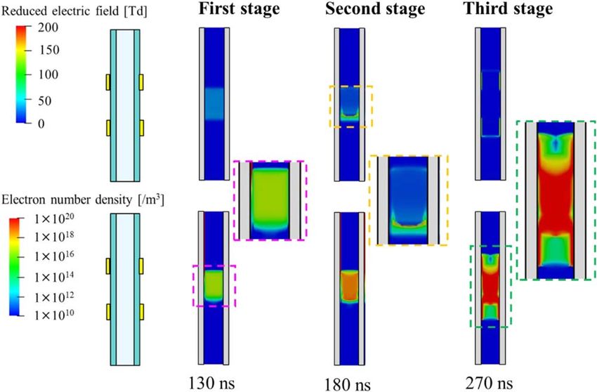
Applied Physics Express 13, 086001 (2020)                                                                                                     LETTER
https://doi.org/10.35848/1882-0786/aba3f2

Numerical analysis of coaxial dielectric barrier helium discharges: three-stage
mode transitions and internal bullet propagation
Yosuke Sato1,2* , Kenji Ishikawa1 , Takayoshi Tsutsumi1, and Masaru Hori1
1
 Nagoya University, Furo-cho, Chikusa, Nagoya 464-8601, Japan
2
 Mechanical Systems Laboratory, Advanced Intelligent Systems, Corporate Research and Development Center, Toshiba Corporation,
1 Komukai-Toshiba-Cho, Saiwai-ku, Kawasaki 212-8582, Japan
*
E-mail: yosuke7.sato@toshiba.co.jp
Received June 1, 2020; revised July 5, 2020; accepted July 7, 2020; published online July 21, 2020

    He discharge in a coaxial dielectric barrier discharge (DBD) device develops in three stages: first, a Townsend-glow-type plasma spreads in the
    region between the electrodes; second, a plasma bullet (streamer type discharge) propagates axially and; third, the bullet transitions into a surface
    discharge at the dielectric surface. These mode transitions are quite different from planar type DBD, in which one discharge mode basically
    corresponds to one discharge pulse. From fluid-based numerical analysis, the bullet propagation is obeyed by trapping with strong electric fields
    induced by grounded electrode underneath the dielectric barrier and by surface charge accumulated on the dielectric surface.
    © 2020 The Japan Society of Applied Physics

D
         ielectric barrier discharge (DBD) has recently at-                     respect to applied voltage and dielectric properties by one-
         tracted great interest for the generation of low-                      dimensional numerical simulation.22,23) However, the nano-
         temperature (cold) atmospheric pressure plasma                         second (ns)-scale dynamics of the reactor type discharges
which could be applied in various fields, such as surface                        have not been elucidated yet and any reason for strong light
treatment,1) medicine,2–4) air-pollution control,5) and material                emission near the electrodes remains unclear. One-dimen-
synthesis with assimilation of carbon dioxide.6,7) DBD                          sional analysis that assumes a uniform axial distribution is
devices are composed of a planar or cylindrical dielectric                      substantially limited in terms of revealing any details of the
and corresponding shaped electrode(s). The planar type                          formation process of plasma inside the reactor type DBD.
generates plasma on and above the dielectric surface. The                       Therefore, multidimensional analysis is required to under-
plasma jet type blows out a discharge. In the reactor type,                     stand detailed plasma generation process in reactor type
discharge stays inside the device. All the device types can                     DBD.
feed a chemically reactive species to the downstream region                        This letter attempts to clarify the detailed plasma formation
of the device.                                                                  process in coaxial reactor type DBD on the nanosecond to
   In planar type DBD, discharge mode changes from                              microsecond timescale using numerical analysis. We will
streamer to glow depending on the applied voltage                               show that plasma generation process in the reactor type DBD
polarity.8) Control of the surface charge can align direction                   is quite different from the planar DBD and also show that an
of movement of charged species in plasma colliding with                         insight of control of the plasma bullet. One of the reasons
background gas and enhancing ionic winds.9) One-dimen-                          why multidimensional analysis of the entire device has not
sional numerical simulations reported that parallel plate                       been performed so far is that the timescales of discharge
helium glow discharges were basically similar to low-                           phenomena and the cycle of applied voltage are significantly
pressure glow discharge in 100 kHz10) and 13.56 MHz11)                          different. In particular, in order to analyze the plasma
and some mode changes occur with saw-tooth voltage.12)                          behavior in recently developed device driven by commercial
   Experimentally, it has been revealed that the plasma jets                    power frequency (50 or 60 Hz)24) throughout an entire cycle,
are a series of rapidly propagating (∼100 km s−1) luminous                      more than 1 × 10⁹ iterations are required due to limitations in
streamer discharges called plasma bullets13) and that the                       the numerical time step (∼1 × 10–12 s).
bullets are ring-shaped.14) The jet type discharges involve                        First of all, we have focused on the beginning phase of
two streamer structures depending on the jet width15) and                       single discharge pulse. The voltage of alternating current
there are three distinct modes with increasing input power.16)                  (AC) with an amplitude of 10 kV under typical discharge
The propagating bullets are guided by a He-air mixing layer                     duration (about 2 μs)25) changes sufficiently small 6 V
with background atmospheric air.17) Photoionization deter-                      (0.06% for 10 kV). This is valid that the applied voltage is
mines the streamer propagation speed, but is not the reason                     regarded as square-pulse waveform of the discharged voltage.
for the propagation itself.18)                                                  Although charge accumulation on the dielectric surface prior
   Discharges in reactor type DBD have been reached a                           to the discharge pulse can affect under AC voltage waveform,
consensus of glow-like in pure He and filament-like in pure                      the simulation of a single discharge pulse provides informa-
Ar.19) As mixing NH3 and Ar, a transition of discharges from                    tion on the complicated dynamics of mode transitions during
filament-like to glow-like was observed and this transition                      a discharge.
was explained by the Penning effect.20) The helium discharge                       A self-consistent, multi-species, multi-temperature plasma
appears nearly uniform, whereas strong emissions are ob-                        fluid model was used to analyze the formation process of
served in the region near the electrodes and dielectric                         plasma inside reactor type DBD. The model is composed of
surface.21) There are comprehensive parametric studies with                     continuity equations for each species, an electron energy

                Content from this work may be used under the terms of the Creative Commons Attribution 4.0 license. Any further distribution of this
                work must maintain attribution to the author(s) and the title of the work, journal citation and DOI.

                                                                        086001-1                         © 2020 The Japan Society of Applied Physics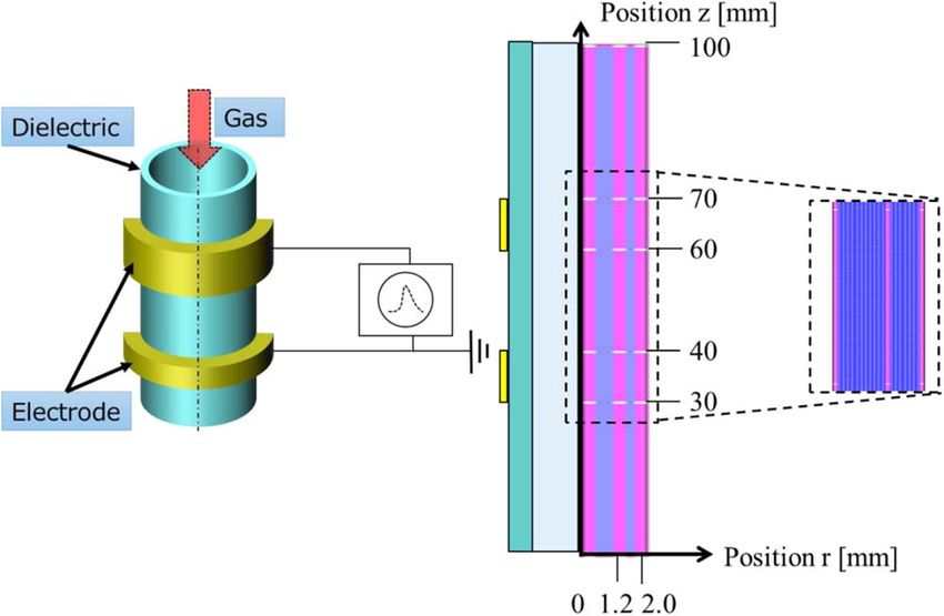
Appl. Phys. Express 13, 086001 (2020) Y. Sato et al.
conservation equation, bulk (gas and dielectric) energy for capturing qualitative discharge behavior. This configura-
equation, and Poisson’s equation for self-consistent electric tion reproduces plasma jets, but the bullets do not jump out
fields. The drift-diffusion model is used to calculate flux from the dielectric tube because the distance between the
terms for all species, as described previously in detail.17,26) electrodes and exit is longer than general plasma jets (up to
The coupled set of nonlinear governing equations was solved 20 mm). In the previous study,31) no bullets were produced
by a commercial plasma solver package.27) by a similar configuration. The plasma discharge stays inside
The chemistry model comprises six species of electron, the tube. Therefore, the computational domain is set inside
helium ions, and metastables (E, He+, He2+, Hem, He2m, and the device including the tube.
He). The reaction pathways and their reaction rate coeffi- Notably, the gas flow is not considered in the simulation
cients for non-electron impact reactions are obtained from a because of the highly disparate timescales of the plasma
previous work.11) The rate coefficients for electron impact discharge phenomena and the fluid flow in typical conditions
reactions are calculated using Boltzmann solver Bolsig+.28) of several slm (standard litter per minute) gas flow rate in
Photoionization in discharges accompanied by streamers reactor type DBD. To model propagation of the bullets
(bullets) has been noted to determine the streamer propaga- outside the tube, the mole fractions of helium and air outside
tion speed, but is not essential for propagation itself,18,29) and the tube are estimated as the background concentration.11,14)
a recent model includes photoionization due to surrounding Initial and boundary condition for the gas and dielectric
O2 molecules photo-ionized by radiation arising from de- temperature is set at 300 K. Temperature rise induced by the
excitation of excited N2 molecules.30) No model involves discharge under several microseconds was less than 0.1 K
photoionization for noble gases. In our previous study and had negligible effects on the discharge dynamics.
without a photoionization model, the propagation speed of When a voltage is applied, a high electric field is induced
the argon streamer agreed well to within an order of between the electrodes and electron acceleration (heating)
magnitude with a number of experimental results results in an increase in the electron temperature, and the
(∼mm/ns).26) Therefore, this does not assume any photo- electron impact reactions generate chemically reacted spe-
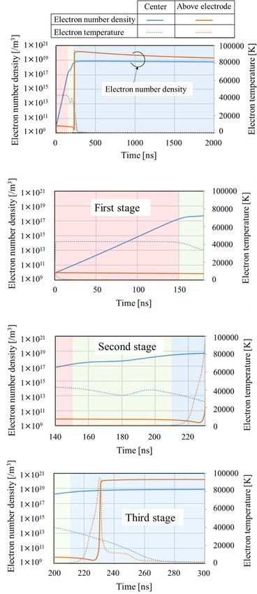
ionization processes. cies. As shown in Fig. 2, the plasma in the device
Figure 1 shows a schematic of the reactor type DBD dynamically changes on the nanosecond timescale. Three
device used in this study. Pure helium flows through a discharge modes are observed. The distributions of reduced
dielectric tube (with a relative dielectric constant of 10) of electric field and electron number density in the gas region
4 mm inner diameter, 0.8 mm thickness, and 100 mm length. are shown. Results are described together with the time
For ease of viewing, the z direction is displayed at 1/5 scale. history of the electron number density and electron tempera-
Two copper electrodes are placed around the dielectric tube ture at the center between the electrodes and near the
and voltage is applied to the upper electrode while the lower dielectric surface above the lower electrode, as shown in
electrode is earthed. Commercial power frequency (50 or Fig. 3.
60 Hz) is assumed for the applied voltage and modeled as Firstly, an electric field of about 30 Td is induced between
15 kV constant voltage. The computational region and electrodes by the applied voltage, and an increase in the
computational mesh are also shown in Fig. 1. Simulations electron number density is observed (first stage). This
are conducted in two-dimensional axisymmetric geometry. discharge mode is the Townsend-glow type, which is nearly
The entire computational mesh is a constructed mesh and the uniform between the electrodes, and the electron temperature
number of cells is 20 000 cells. This resolution is adequate is almost constant at 40 000 K. Previous studies report that
Fig. 1. (Color online) (a) Device configuration of Coaxial DBD device and (b) computational region and computational mesh. Computational region
(left half) and computational mesh (right half).
086001-2 © 2020 The Japan Society of Applied PhysicsAppl. Phys. Express 13, 086001 (2020) Y. Sato et al.
Fig. 2. (Color online) Three stages of plasma electron generation (z direction is displayed at 1/5 scale). (a) First stage (Townsend-glow type discharge),
(b) second stage (streamer or bullet type discharge), and (c) third stage (surface type discharge). The upper row shows the reduced electric field in the gas. The
lower row shows the electron number density in the gas. Nearly uniform distributions are observed in the first stage, an electric field wavefront (streamer head)
is observed in the second stage, and high electron number density near the dielectric surface is observed in the third stage.
helium DBD tends to show glow-like luminance.19,21) Our instantaneously increases to about 350 Td. The electron
results qualitatively agree these reports because the heating induced by this strong electric field causes the
Townsend and glow discharge shows similar near-uniform electron number density near the dielectric to increase to
light emission. 1 × 10²⁰ m−3, which is higher than that between the
When the electron number density reaches about electrodes.
1 × 10¹⁸ m−3 (150 ns), electric field wavefronts form at the Through these three stages that occur within approximately
edge of the plasma region, and the discharge mode transitions 270 ns, a distribution with high electron number density is
to the axially-propagating streamer (bullet) type (second obtained in the DBD device between the electrodes and near
stage). As the discharge passes, the electron number density the dielectric on the electrodes. Secondary ionization by He*
further increases to 1 × 10¹⁹ m−3. The electron temperature and He2* continues for longer than 10 μs. The fact that the
decreases at the center between the electrodes in this stage, inside of the tube is basically Townsend-glow-like and the
because this position is behind the streamer head and the plasma density is high near the dielectric where the electrodes
electric field decreases. This high electric field region are arranged qualitatively corresponds to the visualization
corresponds to the ionization wavefront or streamer head, results so far.19,20) The strong light emission in the vicinity of
and this is driven by a local electric field induced by a local the electrode is confirmed to be due to surface discharge.
space charge from the density difference between positive Plasma in reactor type is formed by different discharge
and negative charged particles. The wavefront starts to modes at the center between the electrodes and near the
propagate when the local space charge reaches dielectric surface. This plasma generation process is
1 × 10¹⁸ m−3, which is the same order of magnitude as quite different from that of planar DBD. In planar type DBD,
bulk plasma density. This streamer type discharge spreads in one mode basically corresponds to one discharge pulse. On
the radial direction while propagating in the axial direction, the other hand, three discharge modes are confirmed to occur
and when it reaches the vicinity of the electrode, the in one pulse in the reactor type DBD. We have performed
propagation stops and the edge reaches the dielectric surface. additional parametric studies (not shown) about important
After that, a gradual change is observed between the parameters. The basic distributions and the three modes do
electrodes. not change by the applied voltage, gap between the elec-
No increase in electron density near the dielectric surface trodes, dielectric tube properties (thickness and dielectric
between the first and second stages can be seen from constant), and inner diameter of the dielectric tube.
Figs. 3(a)–3(c). In the third stage, the discharge mode further Whether the streamer shoots out or stays inside can be
changes to a surface discharge that propagates near the determined in the second streamer formation step. In the
dielectric surface. The surface discharge increases the elec- plasma jet type, discharge becomes a bullet while passing
tron number density near the dielectric surface as it propa- through the surface discharge inside the tube when the
gates, and stops when it spreads to a slightly wider range than voltage is applied and propagates to the outside of the tube.
the electrodes. As this surface discharge passes, the accumu- In the reactor type, discharge starts from a relatively gentle
lated charge density on the dielectric surface increases to Townsend-glow-like discharge between the electrodes and
about 9 × 10⁻⁴ C m−2, and the reduced electric field settles to a surface discharge near the electrodes. Unlike the
086001-3 © 2020 The Japan Society of Applied PhysicsAppl. Phys. Express 13, 086001 (2020) Y. Sato et al.
Fig. 3. (Color online) Time history of electron number density (solid line) and electron temperature (dashed line). (a) Long timescale (all stages), (b) first
stage, (c) second stage, and (d) third stage. Blue represents values at the center between the electrodes and orange represents values near the dielectric surface
on the lower (earthed) electrode.
086001-4 © 2020 The Japan Society of Applied PhysicsAppl. Phys. Express 13, 086001 (2020) Y. Sato et al.
plasma jet, no bullets shoot out of the tube, and instead the ORCID iDs Yosuke Sato https://orcid.org/0000-0002-2772-
2332 Kenji Ishikawa https://orcid.org/0000-0002-8288-6620
bullet is actually formed between the Townsend-glow-like
and surface discharges and travels a short distance of less
than 6 mm. Our parametric study (not shown) confirmed that
the bullet did not shoot out in all the cases, although the size 1) R. R. Borude, H. Sugiura, K. Ishikawa, T. Tsutsumi, H. Kondo, J. G. Han,
and M. Hori, Jpn. J. Appl. Phys. 58, SAAC07 (2009).
and propagation properties changed with conditions. The 2) H. Tanaka, K. Ishikawa, M. Mizuno, S. Toyokuni., H. Kajiyama,
strong electric field of about 350 Td induced by a combina- F. Kikkawa, H. R. Metelmann, and M. Hori, Rev. Mod. Plasma Phys. 1, 3
tion of the ground electrode and the charge accumulation, and (2017).
the dielectric surface promotes the transition to the surface 3) M. Laroussia and X. Lu, Appl. Phys. Lett. 87, 113902 (2005).
4) N. Y. Babaeva and M. J. Kushner, J. Phys. D: Appl. Phys. 43, 185206
discharge, and the distribution spreads slightly beyond the (2010).
electrodes. These results indicate that arrangements of 5) H. H. Kim, Plasma Processes Polym. 1, 91 (2004).
electrodes (shape of electrodes and position of 0 V electrode) 6) C. Xu and X. Tu, J. Energy Chem. 22, 420 (2013).
7) J. Amouroux and S. Cavadias, J. Phys. D: Appl. Phys. 50, 465501 (2017).
and distance between the electrodes and the tube exit is
8) A. R. Hoskinson, L. Oksuz, and N. Hershkowitz, Appl. Phys. Lett. 93,
important to shoot out the bullet. In fact, the distance is less 221501 (2008).
than 2 cm and 0 V is set as target or surrounding air (virtual 9) S. Sato, H. Furukawa, A. Komuro, M. Takahashi, and N. Ohnishi, Sci. Rep.
ground) in typical plasma jet devices. 9, 5813 (2019).
10) F. Tochikubo, T. Chiba, and T. Watanabe, Jpn. J. Appl. Phys. 38, 5244
In summary, we analyzed the formation process of helium
(1999).
plasma in the coaxial DBD using a plasma fluid model. 11) X. Yuan and L. L. Raja, IEEE Trans. Plasma Sci. 31, 495 (2003).
Results indicate that plasma forms in the reactor type DBD 12) K. Gao, R. Liu, P. Jia, C. Ren, K. Wu, X. He, and X. Li, AIP Adv. 9, 115210
through three discharge modes. Firstly, a Townsend-glow- (2019).
13) X. P. Lu and K. K. Ostrikov, Appl. Phys. Rev. 5, 031102 (2018).
like discharge is generated between the electrodes, and when 14) N. Mericam-Bourdet, M. Laroussi, A. Begum, and E. Karakas, J. Phys. D:
the space charge due to the difference in positive and Appl. Phys. 42, 055297 (2009).
negative charged species densities reaches the same level as 15) G. V. Naidis, J. Phys. D: Appl. Phys. 43, 402001 (2010).
that of the bulk plasma, an electric field wavefront is formed 16) J. L. Walsh, F. Iza, N. B. Janson, V. J. Law, and M. G. Kong, J. Phys. D:
Appl. Phys. 43, 075201 (2010).
and a streamer- (bullet-) like discharge develops in the 17) D. Breden, K. Miki, and L. L. Raja, Plasma Sources Sci. Technol. 21,
axial direction. Finally, when the electric wavefront 034011 (2012).
reaches the dielectric surface, it transitions to a surface 18) D. Breden, K. Miki, and L. L. Raja, Appl. Phys. Lett. 99, 111501
discharge emphasized by the accumulated charge, and the (2011).
19) X. J. Shao, N. Jiang, G. J. Zhang, and Z. X. Cao, Appl. Phys. Lett. 101,
discharge propagates to the full electrodes. At this time, 253509 (2012).
the surface charge density is about 9 × 10⁻⁴ C m−2. 20) Z. S. Chang, C. W. Yao, S. L. Chen, and G. J. Zhang, Phys. Plasmas 23,
Compared with 1 × 10¹⁹ m−3 between the electrodes, the 093503 (2016).
21) X. Lu, Z. Jiang, Q. Xiong, Z. Tang, X. Hu, and Y. Pan, Appl. Phys. Lett. 92,
electron number density near the electrodes is as high as
081502 (2008).
1 × 10²⁰ m−3, which confirms that the strong emission in this 22) S. Gadkari and S. Gu, Phys. Plasmas 24, 53517 (2017).
region is due to the surface discharge. In the reactor type 23) D. Petrovic, T. Martens, J. van Dijk, W. J. M. Brok, and A. Bogaerts, J.
DBD, the development of the bullet is confirmed as in the Phys. D: Appl. Phys. 42, 205206 (2009).
24) K. Takeda, T. Kumakura, K. Ishikawa, H. Tanaka, M. Sekine, and M. Hori,
case of the plasma jet, but it is trapped by the strong electric
Appl. Phys. Express 10, 036201 (2017).
field (momentary about 350 Td) due to the electric field 25) X. Li, N. Zhao, T. Fang, Z. Liu, L. Li, and L. Dong, Plasma Sources Sci.
induced by a combination of the ground electrode and the Technol. 17, 015017 (2008).
accumulated charge, and the propagation distance is short at 26) Y. Sato, K. Ishikawa, T. Tsutsumi, A. Ui, M. Akita, S. Oka, and M. Hori, J.
Phys. D: Appl. Phys. 53, 265204 (2020).
6 mm and it immediately transitions to a surface discharge. 27) Esgee Technologies, VizGlow: Plasma Modeling Software for Multi-
This suggests the possibility of controlling the plasma bullet Dimensional Simulations of Non-Equilibrium Glow Discharge Systems,
not only by the distance between the electrode and the tube User Manual, Version 2.2 (Esgee Technologies Inc., 2017).
outlet, but also by the electrode structure (arrangement). 28) G. J. M. Hagelaar and L. C. Pitchford, Plasma Sources Sci. Technol. 14, 722
(2005).
Acknowledgments The authors would like to thank Professors Hiroki 29) X. Lu and M. Laroussi, J. Appl. Phys. 100, 063302 (2006).
Kondo and Makoto Sekine of Nagoya University for fruitful discussion. The 30) A. Bourdon, V. P. Pasko, N. Y. Liu, S. Celestin, P. Segue, and E. Maroude,
authors also thank Akio Ui, Masato Akita, and Shotaro Oka of Toshiba Plasma Sources Sci. Technol. 16, 656 (2007).
Corporation for encouragement of this research. 31) U. N. Pal et al., J. Phys. D: Appl. Phys. 42, 45213 (2009).
086001-5 © 2020 The Japan Society of Applied PhysicsYou can also read