Octet lattice-based plate for elastic wave control - arXiv
←
→
Page content transcription
If your browser does not render page correctly, please read the page content below
Octet lattice-based plate for elastic wave control
                                                  Giulia Aguzzi1,* , Constantinos Kanellopoulos1 , Richard Wiltshaw2 , Richard V.
                                                  Craster2,3,4 , Eleni N. Chatzi1 , and Andrea Colombi1
                                                  1 Department of Civil, Environmental and Geomatic Engineering, ETH Zürich, Zürich 8093, Switzerland
                                                  2 Department of Mathematics, Imperial College London, London SW7 2AZ, United Kingdom
                                                  3 Department of Mechanical Engineering, Imperial College London, London SW7 2AZ, United Kingdom
                                                  4 UMI 2004 Abraham de Moivre-CNRS, Imperial College London, London SW7 2AZ, United Kingdom
                                                  * aguzzi@ibk.baug.ethz.ch
arXiv:2110.13590v1 [physics.app-ph] 26 Oct 2021

                                                  ABSTRACT

                                                  Motivated by the importance of lattice structures in multiple fields, we investigate the propagation of flexural waves in a
                                                  thin woven plate augmented with two classes of metastructures for wave mitigation and guiding, namely metabarriers and
                                                  metalenses. The cellular architecture of this plate invokes the well-known octet topology, while the metadevices rely on novel
                                                  customized octets either comprising spherical masses added to the midpoint of their struts or variable node thickness.
                                                  We numerically determine the dispersion curves of a doubly-periodic array of octets, which produce a broad bandgap whose
                                                  underlying physics is elucidated and leveraged as a design paradigm, allowing the construction of a metabarrier effective
                                                  for inhibiting the transmission of waves. More sophisticated effects emerge upon parametric analyses of the added masses
                                                  and node thickness, leading to graded designs that spatially filter waves through an enlarged bandgap via rainbow trapping.
                                                  Additionally, Luneburg and Maxwell metalenses are realized using the spatial modulation of the tuning parameters and
                                                  numerically tested. Wavefronts impinging on these structures are progressively curved within the inhomogeneous media and
                                                  steered toward a focal point. Our results yield new perspectives for the use of octet-like lattices, paving the way for promising
                                                  applications in vibration isolation and energy focusing.

                                                  Introduction
                                                  Lattice materials are engineered periodic structures whose cellular architecture originates from a network of entangled structural
                                                  elements (e.g., rods, beams, or plates)1 . Their high strength-to-weight ratio, combined with recent progress in additive
                                                  manufacturing, renders them particularly attractive for the scientific community; their unique mechanical performance has been
                                                  extensively explored2 , with broad application in biomedicine, aerospace and energy absorption. It is only recently that these
                                                  have drawn attention for their ability to diffract waves and behave as filters3 that forbid energy transmission across selected
                                                  frequencies, known as bandgaps4 . The periodic nature of these reticulated structures is often at the root of their attenuation
                                                  mechanism, leading to Bragg scattering effects5 that dominate the spectrum of their band structure6 . Bragg bandgaps arise
                                                  through destructive interference, occurring when the wavelength of a wave is comparable to the fundamental period of the
                                                  media they are propagating through, and typically occur at frequencies too high to be exploited. Much work has been done
                                                  to broaden Bragg bandgaps by introducing locally resonant objects, whose resonance coincides with the Bragg frequency7–9 ,
                                                  wherein lattice vectors are carefully chosen such that these frequencies coincide.
                                                      Despite offering wave control, Bragg-based frame designs suffer from a periodicity requirement that forces their char-
                                                  acteristic size to comply with the targeted wavelength4 thus, limiting their role. To overcome this limitation, attempts are
                                                  being made to design lattices with resonance-induced bandgaps that, unlike their phononic counterpart, exploit the coupling
                                                  between propagating waves and resonating components and offer greater tuning flexibility at subwavelength scale (i.e., the
                                                  size of the unit cell can be orders of magnitude smaller than the wavelength). These structures form a subset of single-phase
                                                  metamaterials10–12 that use auxiliary resonators or inborn resonant modes of the lattice to hybridize propagating waves and
                                                  inhibit their transmission. Common practice for their implementation includes, for instance, embedding stand-alone resonant
                                                  elements (e.g., cantilever beams10 ) into an original frame-based topology, similarly to the solution proposed by Li et al.13 A
                                                  different method, adopted by An et al. in14 uses, instead, the constitutive matrix of a body-centered cubic (BCC) lattice and
                                                  constructs an integrated resonator via radius jump of its strut cross-section. The BCC cell is only one of the Bravais lattices5, 15
                                                  potentially serving as metamaterials. Among the fourteen types known to exist in the three-dimensional space5 , the octet
                                                  design16 is an example of face-centered cubic (FCC) topology with promising attenuation potential. The dispersive behavior of
                                                  this lattice, already renowned in statics for its high strength combined with a slender lightweight profile17 , has been outlined
                                                  by Arya et al.18 who show that the octet supports a bandgap whose existence depends upon the aspect ratio of the struts, but
                                                  do not investigate the underlying physics of its generating mechanism; only briefly suggested by Gerard et al.19 . In addition,
most of the state-of-the-art research on such a FCC cell resort to frequency gaps produced by attached resonators12 or use
it as a constitutive matrix of multi-phased materials20, 21 , without delving into its inherent resonant modes. The absence of
an overarching dynamic assessment of this architecture in the existing literature emphasizes the novelty of our work, which
proposes the octet topology as a metamaterial lattice endowed with an energy gap stemming from the bending local resonance
of its beam-like members. Moreover, due to the arrangement and behavior of wave propagation through the struts, we show that
the octet cells form a medium in which flexural resonances naturally coincide with the Bragg frequency - as observed within
the eigenmodes permitted by Floquet-Bloch waves.
     In aerospace and aircraft engineering, lattice plates are frequently used as structural components or filling in sandwich panels1
that, whilst providing lightness to the structure2 , are liable to significant vibrations. The propagation of such vibrations in solid
thin plates, occurring in the form of Lamb waves with different polarization, has been extensively documented22, 23 resulting in
a variety of metamaterial-based solutions. Prominent among these are metabarriers (or metawedges24 ) encompassing clusters
of rods whose longitudinal resonant mode couples with the flexural waves propagating in the plate and triggers the opening of
bandgaps25, 26 . To enlarge the frequency band of such barriers, that owing to local resonance offer a fairly limited range of
applicability, graded designs have been explored, where the spatial variation of the tuning parameter, rod height, yields a wider
spectrum of attenuation associated to the so-called Rainbow trapping effect27, 28 . The theory underpinning these metastructures
can be easily applied to octet-based plates, with the longitudinal resonances replaced by the bending mode of the struts and the
rod height by the parameters of the beam-like members. Based on these considerations, a number of parameters exist in the
literature to tune the resonance-bandgap, two of which are of particular interest for the present study, namely auxiliary point
masses and joint stiffness. Junyi et al.12 proposed equipping the end of cantilever beams, added to primary 3D Bravais lattices,
with point masses whose size governs the gap frequency independently of the geometry of the base lattice. Shortly before this,
the same spherical masses were attached to the joints of a Kagome lattice by Liu et al.29 to stiffen its connections and open a
bandgap tied to the rod-node vibration.
     Beyond widening the bandgaps, graded designs lay the foundation for a multitude of compelling wave control possibilities.
One of these dates back to the nineteenth century and the seminal work of Maxwell on so-called flat or gradient-index (GRIN)
lenses30 . These are effective, aberration-free devices that leverage composite structures to adjust the spatial distribution of
the refractive index within a bounded region and ultimately shape the incident wavefronts. The Luneburg lens31 is a type
of spherical GRIN lens that diverts any collimated beam colliding at its boundaries to a diametrically opposite focal point.
Similarly to this system, underpinned by a refractive index that increases radially from the outer toward the center of the graded
area, the Maxwell fish-eye lens, bends the trajectories of rays originated by a point source at its surface and focuses them in
a mirrored image point. While building such lenses with ordinary composite materials appears a daunting task, employing
phononic crystals32, 33 or metamaterials34, 35 considerably relieves this complexity. From a metamaterial perspective, the cluster
of locally resonant rods with graded height, previously discussed, has proven an effective candidate for the design of GRIN
lenses36–38 . Its rod-resonance bandgap, besides providing attenuation, serves as tuning variable for the phase velocity of waves
traveling in the metastructure and leads to applications at different scales, from acoustics36 to seismology39 . In terms of frame
structures, the research on wave guiding is still at a primordial state, mainly confined to two-dimensional lattices40–43 and
yielding, only in a handful of cases, to more sophisticated effects. Xie et al.44 and Zhao et al.45 were among the few to design
2D and 3D flattened Luneburg lenses consisting of a three-dimensional truss-based square lattice, to manipulate waves in the
ultrasound regime. A recent study46 , on the other hand, has explored the propagation of elastic waves in three-dimensional
lattices, including specifically the octet cell. Although similar to our investigation with respect to the choice of topology, no
bandgap is reported in this case and only the anisotropic character of the structure is emphasized, with no explicit reference to
shaping wave trajectories via graded octet lattices. Therefore, the lack of existing literature on gradient-index lenses designed
with octet lattices further motivates our work.
     Here we take the octet lattice analysis one step further by using this geometry to realize a reticulated plate and two types of
integrated devices for flexural wave mitigation and control. Following a dispersion analysis of the proposed standard octet cell,
the bandgap and its underlying generation mechanism are revealed, resulting in the identification of two tailoring parameters.
Auxiliary masses, embedded in the midpoint of the struts, or variable joint thickness are used to tune the frequency range
with forbidden propagation as well as the phase velocity spatially within the lattice. To avoid redundancy of results, only
those stemming from the addition of masses to the primary cell are reported here; varying the node thickness produces similar
outcomes. Two metabarrier designs are discussed, the first characterized by constant auxiliary masses and the second relying
on the grading strategy to trap and hinder wave transmission over a wider frequency band. Finally, Luneburg and Maxwell
lenses are built by smoothly increasing the supplementary spherical masses radially from the boundaries to the center of the
devices. We find the octet cell and subsequent customizations possess desirable dispersive properties easily coaxed to required
frequencies, these properties are readily exploited to create a variety of devices able to manipulate the propagation of waves
over a variety of scales, in both a subwavelength (lenses) and Bragg (metabarriers) scattering regime.

                                                                                                                                2/15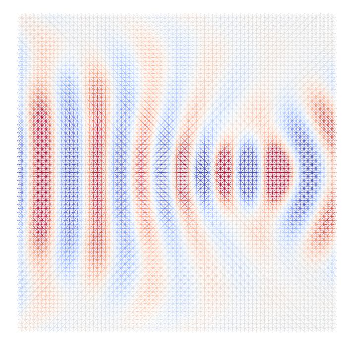
(a)                                       fundamental unit cell                     (b)
                                                  a2
                                                                                                Source                                            Octet Lattice Plate

                                       y                                                                                                                 Output Points
                                             x
                                        z
                                                                            a1
                                                          lstrut                      y
 a2                                                                    ϑz
                                                                                 ϑx         x                      Sweep Source
   y                                                  w

                                                                                                                               Spectrum
         x   a1                                                             ϑy

                                                                                                    u
   z                         l                    u         v
                                                 Euler-Bernoulli beam model                              0              0.07              0.1            9
                                                                                                             Time (s)                     Frequency (kHz)

  (c)                                                                                 (d)
                                                                                                                                                               tnode
                                                                                                                                                tstrut
                                                                   tmass
                                                                                                                                                               lnode

                                                                   m

                                                           added mass                                                                              node area

Figure 1. Cell designs and setups for dispersion and parametric analyses. (a) 2D standard octet lattice with fundamental unit cell depicted in the zoom (a1 =
(l, 0, 0) and a2 = (0, l, 0)). (b) Finite lattice plate (3.6 x 1.2 x 0.03 m) for the validation of the band structure via time-transient simulations in Real-ESSI. The
constitutive unit corresponds to the standard octet reported in (a). The plane sweep source and line of points where the output signal is recorded, spaced 0.03 m
apart and located on the nodes of the lattice, are marked in red and blue. (c) Customized octet equipped with spherical masses m, of diameter tmass , (dark color)
added to the midpoint of the struts. (d) Octet with customized joints via tunable node thickness, tnode . The zoomed plot inset shows the node area of length
lnode equal to 2tstrut and of variable thickness tnode .

Results
Octet cell design, dispersion and parametric analyses
Consider a thin reticulated plate, of infinite extension, constructed from repeating unit cells, each comprising a strut network
generating the well-known octet topology16 . We choose a fundamental cell whose edges coincide with the midpoint of the octet
struts, as depicted in Figure 1a, where we define physical basis vectors a1 and a2 , assumed collinear with the Cartesian axes x
and y. We consider struts of circular cross-section, of diameter tstrut = 1 mm, Young’s modulus E = 1.7 GPa, density ρ = 450
kg/m3 and  √ Poisson’s ratio ν = 0.3. We take the length of our lattice vectors to be l = 3 cm and hence have a strut length of
lstrut = l 2/2. The circular cross-section provides axial symmetry and prevents stress concentration that would instead arise in
sharp-edged profiles, e.g., square cross-section.
     It is sufficient to consider waves propagating through the fundamental cell as the phase shift from cell-to-cell is completely
described by the dispersion relation between eigenfrequencies and Bloch-wavevector, corresponding to the red dotted line
reported in Figure 2a (see Methods). Despite the complexity of this folded band structure, three main frequency bands can be
clearly identified.
     In the low-frequency limit, from 0 to 2 kHz, the spectrum is dominated by zero-order modes similar to the solutions of
Lamb’s characteristic equations in solid, homogeneous, and thin plates for long wavelengths22 . The underlying lattice structure
has subwavelength behavior and wave propagation closely resembles an equivalent continuum supporting three propagating
waves, respectively two with transverse and one with longitudinal polarization47 . Among these, the asymmetric flexural mode,
simply denoted as A0 mode in Figure 2a, is the most attractive for its ease of activation and amount of carried energy hence, the
cornerstone of this study.
     At higher frequencies (2 to 5 kHz), the wavelength reduces rapidly and waves interacting with the detailed geometry of
the cell open a bandgap between 3.85 and 5.08 kHz. Waves with frequency content matching this range are prevented from
penetrating the octet lattice while being trapped by the bending vibrations of its struts. These deformations emerge as flat bands
in the lower bound of the forbidden interval and serve as evidence of its local resonance-based generating mechanism48 . They

                                                                                                                                                                         3/15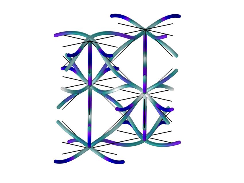
(a)                                                                                (b)                   (c) High-Frequency mode
                  8                                                                       BG closing mode                         7

                                                                                                                Frequency (kHz)
                  7                                                                                                                   ffixed                               Bandgap
                                                                              e                                                                                 5.1
                                                                          mod                                                     5
                  6                                                 e   q
                                                             -   Fr
                                                          gh
                                                        Hi

                                                                                                                                                         Frequency (kHz)
                                                                                      z                                           3
Frequency (kHz)

                  5                                                                                                                       Wave vector
                                                                                            x
                                        BANDGAP
                  4
                                                                                          BG opening mode
                                                                                                                                               A0 mode
                  3                                                                                                       1.8
                                                                                                                                                                1.7

                                                                                                                Frequency (kHz)
                  2                                                                                                                                                  0 4      8 12 16
                                                                                                                                      ffixed                       added mass ratio (m/mref )
                                           e
                                         od
                                        m

                  1                                                                   z                                                                                     standard octet
                                        0
                                      A

                                                                                                                                                                            m = 4 mref
                                                         Bloch Analysis                     x
                  0                                                                             |u|                               0                                         m = 8 mref
                      Γ                                                           X                                                       Wave vector                       m = 12 mref
                                        Wave vector                                         0         max                                                                   m = 16 mref

                      Figure 2. Dispersion analysis. (a) Band structures of the standard octet crystal and finite plate (Figures 1a, b) computed with Comsol Multiphysics (red) and
                      Real-ESSI (black). The Γ-X wavevector in the reciprocal space represents waves propagating in the ex direction in the physical system. The red curves are
                      obtained via Bloch-eigenvalue analysis on the fundamental unit cell of Figure 1a. The black branches derive from the fast Fourier transform (FFT) of the z-wise
                      signal recorded on the receivers of Figure 1b, where they are denoted as output points and colored in blue. (b) Bandgap (BG) opening and closing eigenmodes,
                      respectively at 3.85 and 5.08 kHz. (c) Sensitivity analysis on the dispersion curves of the customized octet cell (Figure 1c) for increasing m, where mre f =
                      ρA2tstrut .

                      cluster around the first flexural frequency of a clamped-clamped Euler-Bernoulli (EB) beam, geometrically equivalent to the
                      struts in the octet and defined by:
                                                 s
                                           22.4     EI
                              fclamped =     2
                                                                                                                                              (1)
                                         2πlstrut ρA

                      The analytical flexural frequency in Equation (1), equal to 3.85 kHz, corresponds to the bandgap opening bound and poses
                      as a design variable for tailoring the bandgap frequency range. By considering the octet struts as equivalent EB beams with
                      clamped edges and bending resonance11 , the bandgap opening frequency can be estimated via Equation (1) and, consequently,
                      also the correlated attenuation zone49 . This simplification reduces the complexity of the octet cell to individual beams clamped
                      at the nodes, facilitating the tuning of design parameters. This clamped-clamped nodal behavior relies on a network of highly
                      connected struts peculiar of the octet topology. As outlined in Wang et al.49 highly connected lattices (here intersection points
                      of 12 members at a node) yield a clamped-clamped behavior of the struts at the nodes. Similarly to Nolde et al.50 , our flat bands
                      at fclamped correspond to standing waves induced by the fundamental resonance of vibrations along clamped-clamped beams.
                      This behavior is highlighted in the BG opening eigenmode displayed in Figure 2b, where the nodes stand still. Furthermore,
                      such a fundamental resonance fits exactly within the length of the primitive lattice vectors (a half our conventional unit cell),
                      hence the propagation regime is identical to Kaina et al.7 in which the wavelength of the fundamental clamped-clamped
                      resonance is twice that of the modulus of the primitive lattice vectors; subsequently the Bragg frequency and fclamped coalesce,
                      resulting in destructive interferences producing a broad bandgap. Wang et al.49 remarks that bandgaps, in this setting, are
                      generated by local resonances and not Bragg scattering; however, in the case where beams are parallel to and of the same
                      length as the primitive lattice vectors, one expects a medium in which the fundamental resonances naturally match the Bragg
                      frequencies, all of which are properties the underlying octet cell possesses.
                           Beyond the bandgap, approximately from 5 to 8 kHz, additional dispersive modes populate the spectrum of the dispersion
                      relation, mimicking waves that propagate at the strut level accompanied by roto-translations of the nodes. In particular, a branch
                      with predominant orientation along z, denoted as high-frequency mode in Figure 2a, can be observed. Owing to its polarization,

                                                                                                                                                                                             4/15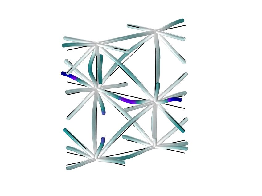
this defines the upper bound of the attenuation zone (see top inset in Figure 2b), in contrast to the two modes converging at 4.7
kHz, which exhibit, instead, in-plane deformations.
     One known limitation of the Bloch analysis is that only a minority of the computed modes are triggered owing to their
strong source dependence. Hence, a finite octet-based plate, consisting of 120 x 40 cells equivalent to the one of the infinite
study (Figure 1b), is adopted to corroborate the predicted band structure via time-domain simulations (see Methods). The
outcome of this analysis is shown as a background of the dispersion curves in Figure 2a, where the branches involving
out-of-plane deformations are predominantly excited. Almost complete superposition can be appreciated between the A0 and
high-frequency modes of the frequency-wavenumber spectrum and that of the Bloch analysis. A small discrepancy arises only
in the higher-order modes and in the upper bound of the bandgap, with a downward shift of about 0.05 kHz in the results of
the time-transient simulation. From 2 to 4 kHz, additional modes, generated by waves with polarization in the lattice plane
(longitudinal or shear), are effectively captured by the finite model. Overall, the results of these two types of analyses reveal
good agreement and justify their joint application in the following sections.
     The octet unit outlined hitherto, comprising 24 woven struts of constant, circular cross-section, is denoted as the standard
cell. Remarkably, a local resonance-induced bandgap originates in this single-block lattice owing to the refined topology of its
design, thus paving the way for a variety of parameters to be leveraged in tuning the dispersion relations. While geometrical
and material properties emerge as the primary natural candidate, their influence on the octet band structure has already been
assessed18 ,51 . The focus here shifts to two novel, so-called, customized octet cells whose parameters allow tailoring the band
structure without affecting the original geometry, i.e., cell width and strut thickness. In the customized cell of Figure 1c the
midpoint of the struts is endowed with auxiliary spherical masses, m, of diameter tmass , as this undergoes major displacements
when bending deformations are activated. In order to retain a monolithic structure, easier to 3D print with modern techniques,
the supplementary mass is made of the same material selected for the lattice and is expressed as a multiple of a reference value,
mre f = ρA2tstrut . The diameter tmass in Figure 1c is then derived upon definition of this quantity and its practical feasibility,
with respect to the thickness of the struts, is adequately verified in each of the proposed devices. The spheres are added as
point masses in the finite element model in Comsol 5.6 and the sensitivity analysis is performed on the single customized unit
via Bloch theory. Likewise the approach adopted for the standard octet cell, the struts are treated as equivalent fixed-fixed
Euler-Bernoulli beams with the distributed mass, ρAlstrut , incremented by the point mass m. Naturally one expects these added
masses to provide a damping over the whole band structure reducing the frequencies of comparable eigenmodes, as observed in
Figure 5b. The first fundamental frequency, governing the position of the bandgap, has an inverse reliance on the added mass,
as already analytically proven by Low et al.52 . When m increases, the bandgap is instantly shifted to lower frequencies, from
the range 3.85-5.08 kHz to 1.73-2.74 kHz in the rightmost inset of Figure 2c, altering the A0 and high-frequency modes. Each
point in these dispersion curves has an associated phase velocity, v p = ω/kx 5 , which decreases when moving from lighter to
heavier masses at constant frequency (red line in Figure 2c), thereby animating the lattice with slower waves. Similar outcomes
arise when exploring the customized cell in Figure 1d. Following the analogy between octet struts and clamped EB beams,
we harness the topology of the connections in the lattice to modify the boundary conditions of the equivalent beams and their
natural resonant frequency, in turn affecting the band structure of the architected cell. A node area of length lnode , twice as long
as tstrut , is identified in Figure 1d, where the diameter of the section, tnode , is expressed as a fraction of the original thickness
tstrut . By decreasing this parameter from tstrut to 0.2tstrut , clamped-like joints are replaced by quasi-hinged connections that
allow almost free rotations between contiguous struts. This yields a substantial reduction of the node bending stiffness, which
is proportional to the moment of inertia, I, and consequently to the joint thickness, tstrut 4 . The bandgap opening frequency is

therefore shifted from the value reported in Equation (1) to that of a simply supported beam, f pinned = 0.44 fclamped , entailing a
slope-related change in the low (A0 ) and high-frequency branches. Again, the phase velocity of the waves diminishes, leading to
slower waves propagating in the hinge-like octet lattice and faster waves being instead transmitted by the stiffer, clamped-based
frames.
     In designing the cell of Figure 1d, compliant joints were preferred over decoupling the struts with prefabricated hinge-
connectors as they preserve the single-phase material while allowing a gradually varying stiffness of the connections. Although
beyond the scope of this study, it is important to point out that this choice may cause a high stress concentration in the joints
that must be examined prior to fabrication.

Wave propagation in finite meta-lattices
The computational domain, depicted in Figure 3a, is a 3 cm thick reticulated plate assembled by spatially tessellating the
standard octet cell illustrated in Figure 1a. A so-called meta-area lies within this structure, where the parameters of the octet,
introduced in the previous Section and expressed in terms of supplementary masses or joint stiffness, are progressively tuned to
yield exotic attenuation or wave guiding phenomena. Therefore, two types of devices are built, as reported in Figures 3b and c:
the metabarriers and metalenses. The metabarriers leverage an arrangement of customized octet units, either tailored at the
same or diverse frequencies, to generate an inhibited frequency range, where the displacement field vanishes and ultimately

                                                                                                                                 5/15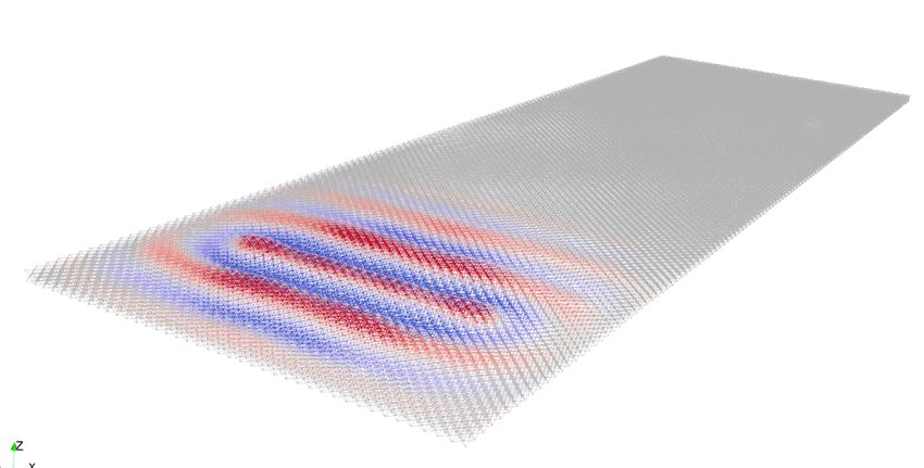
(a)                                                                                                                                                       Ncells,
                                                                                                                                                                    y

                               Ricker Source
                                                                                                           N cells, x
                                       Spectrum                                                                                   Meta-a
                                                                                                      Sour                               re   a
   uz

                                                     fc                                                    ce                                                           ALID BC
                        Time (s)                  Frequency (kHz)

                             Sinusoidal Source
                                                          fsine
                                       Spectrum

                                                                                          La t
   uz

                                                                                              tice
                                                                                                   Plat                 z
                        Time (s)                  Frequency (kHz)                                      e                                              Plate close-up
                                                                                                                    y       x

(b)                                                  Metabarrier                                                                Metalens                        (c)
                             Constant                                    Graded                                                                     R
Ny, metabarrier

                                                                                                             varying
                                                                                                            properties

                                      m = 14mref                    m1 m2 m3 m4 m5 … mn

                             Nx, metabarrier

                  Figure 3. Setup for time-transient simulations in Real-ESSI. (a) Lattice plate made of standard octet units as detailed by the close-up. The meta-area (dashed
                  black line) consists of embedded-mass octets arranged as rectangular metabarriers or circular metalenses, as reported in (b) and (c). Absorbing boundary
                  conditions with quadratically increasing damping53 (ALID) are implemented on all four edges of the plate. The two sources used for the metabarriers (Ricker)
                  and metalenses (sine) are sketched in the inset. (b) Metabarries of customized cells with auxiliary masses. On the left side, the constant setup (50x20) encloses
                  cells with m=14mre f . The graded configuration is formed by 30 x 20 cells of progressively increasing masses, mn with n = 1, ..., 15. Each layer comprises two
                  rows of octet cells with identical supplementary mass. (c) Layout for Luneburg and Maxwell metalenses featuring concentric circular layers with variable point
                  masses. In both cases, the lens radius, R, consists of 12 cells of width l and the source is a sinusoidal excitation tuned at the design frequency of the lens.

                  shield a target area. Conversely, the metalens relies upon the spatial variation of lattice properties to modify the refractive index
                  in an inhomogeneous bounded region and manipulate wave trajectories, eventually offering the opportunity to focus and harvest
                  vibration energy.

                  Wave propagation in lattice metabarriers
                  Two lattice metabarriers, comprising mass-embedded octets, are implemented within a lattice plate made of 120 by 40 standard
                  cells, arranged as per the configuration in Figure 3a, and separately investigated in this section.
                      Illustrated in Figure 3b is the 50x20 cells constant metabarrier, where the struts of the octets are equipped with midpoint
                  masses, m, equal to 14mre f (tmass = 3.5 mm), yielding an attenuation zone from 1.8 to 2.8 kHz (gray region in Figure 4d).
                  The metastructure is assessed under excitation of a 60ms Ricker wavelet located at a distance of 45 cells to guarantee a plane
                  wavefront. The spectrum of the source, with dominant component along z, is centered on the bandgap, at 2.1 kHz.
                      The recorded displacement field uz , filtered inside the bandgap at two sequential instants in Figures 4a and c (see video
                  in the Supplementary Material), unveils the attenuation potential of the lattice metabarrier, based on Fano-like resonances54 .
                  At t=7.2 ms, the flexural waves scattered by the resonating mass-struts in the metawedge interfere destructively with the
                  unscattered incoming field, impeding the transmission of energy55 . The resulting energy gap, originated by the hybridization
                  between the asymmetric propagating Lamb wave and the coalescence of the resonant bending mode of the struts and Bragg
                  scattering, induces splitting of the incident wavefront56 , as depicted in Figures 4a, c.
                             C1, c2, c3 etc
                      This mitigation mechanism, already introduced in the previous Section, is further corroborated by the spectrum of two
                  waveforms, r1 and r2 in Figures 4a, b, located on the masses of a cell belonging to the first row of the metabarrier. The signal
                             represent cell 1, cell
                  of the leftmost mass-strut (blue line in Figure 4b) exhibits a pronounced Lorentzian symmetric peak centered at the resonant
                  frequency fr (1.8 kHz), whilst the second waveform, r2 , reveals the typical asymmetric profile, where a sharp enhancement of
                             2 etc
                  the spectrum prior to fr is followed by a transmission drop (antiresonance)54 . This Fano-type interference, limited to a narrow

                                                                                                                                                                             6/15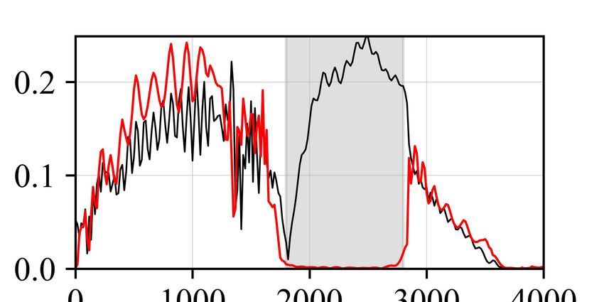
(a)                      m
                         m                                                                         (b)
                                                                                                                1
                                                                              zoom-in                                                                               r1
                                           metabarrier                                                                                                              r2
                                                                                                                         mass-strut

                                                                                                    Spectrum
                          r1 r2                                                  r1 r2                                  resonance fr
            incident
                                                                                                               0.5
                                                                                                                                                  antiresonance

                                                  t = 7.2 ms                   1 cell
                                                                                                                0

(c)                                                                                               (d)
                                                                                                                                       fr
                                                                                                               0.2                                      reflected
                                           metabarrier                        zoom-in                                                                     signal

                                                                                                    Spectrum
            reflected     r3              r4                                                 r4
                                                                         r3                                    0.1

                                                                                                                                              bandgap
                                                  t = 8.8 ms                  25 cells                         0
                                                                                                                    0           1             2          3               4
          uz (arb. units)                                                                                                           Frequency (kHz)
      min     0    max                                                                                              Before Metabarrier (r3)        Inside Metabarrier (r4)

      Figure 4. Temporal and spectral wave fields of the constant metabarrier. (a) Propagating Lamb waves filtered within the bandgap (1.8 - 2.8 kHz). The output
      signal is recorded in two points, r1 and r2 , arranged on the midpoint of the struts atop the embedded masses in order to validate the hypothesis of hybridization
      bandgap. Their spectrum is reported in (b). (c) Filtered displacement field at a later time instant. The back propagating, reflected wavefront is emphasized by
      the red arrow. Two receivers, located respectively before and within the barrier, are shown in the zoom. Their spectra are compared in (d), after normalization
      with the peak value of (b).

      bandwidth if only the first line of cells in the metabarrier is considered, intensifies when leveraging an array of octets tuned
      all at the same resonant frequency. By inspecting the spectral displacement of a point located at the core of the metabarrier,
      after 25 cells (r4 ), this effect becomes evident. The resonances of the mass-equipped struts interact constructively yielding a
      wider attenuation zone that extends from fr to their antiresonance57 , as reported by the gray region and red signal in Figure 4d.
      Furthermore, by comparing this spectrum with the displacement field in a receiver on the edge of the metastructure (r3 ), black
      line in Figure 4d, we observe that the majority of the energy with frequency content within the forbidden range is converted
      into reflections56 . The wavefront impacting on the metabarrier at 7.2 ms, propagates backward in the plate at t=8.8 ms (Figure
      4c) after  interacting
             NOTES-             with the resonating members.
                         Constant:
           Although      effectively
             - Source Ricker centeredhampering    wave Hz
                                              at 2100    transmission within the bandgap, the constant metawedge exhibits a fixed frequency
      range- of Bandgap
                 application     stemming    from   the
                              between 1800 and 2500 Hz  resonant   nature of the attenuation zone that, whilst broadband and easily tuneable,
      entails- spatially   localized  phenomenon.
                 Wave Propagation – Signal filtered   A  mitigation  device, equipped with smoothly increasing masses, is designed in order to
      overcomewithinthis drawback,
                           the bandgap as these were   proven   to affect the frequency content of the prohibited range (see Figure 2c). The
      graded    metabarrier,     with masses
             - Masses m = 0.000010kg = 14mref  m 1 to m 15  ranging from   3mre f to 42mre f , respectively with tmass from 2 to 5 mm, is depicted
      in the right inset of Figure 3b and tested with an input Ricker source centered at 3 kHz. Following the inverse relationship
      between added mass and resonant frequency, the heaviest masses (m15 ) govern the opening frequency of the total bandgap,
      while the upper bound depends upon the choice of m1 (see Figure 5b). The evolution of the bandgap is also shown in Figure
      5b and reveals how the frequencies within the bandgap decrease spatially as masses increase from grade to grade; waves of a
      certain frequency propagate through the medium until they reach the spatial location where they exist within a bandgap, at this
      point they are subsequently trapped and back reflected thus, spatially distillating the spectrum following the Rainbow trapping
      effect24, 27, 58 . As a result, our medium possesses a wider stop band, from 1.14 kHz to approximately 5.1 kHz (see gray region
      in Figure 5c).
           Figure 5a illustrates the displacement field filtered over two distinct frequency ranges (see videos in the Supplementary
      Material). Between 1.8 and 2.5 kHz, the wave impinging the metabarrier is almost immediately trapped and scattered by
      the cells with masses equal to 11mre f , owing to the matching with their frequency gap (1.98-3.09 kHz). Similarly, the lower
      frequency field, corresponding to a pass-band filter between 1.2 and 1.5 kHz, travels undisturbed deeper in the metastructure
      until it eventually interacts with the cells of mass 31mre f (bottom inset), the exact location these frequencies occur within the
      varying bandgap.
           As validation, the spectral displacement of a point at the right end of the metawedge is compared to that of a receiver

                                                                                                                                                                         7/15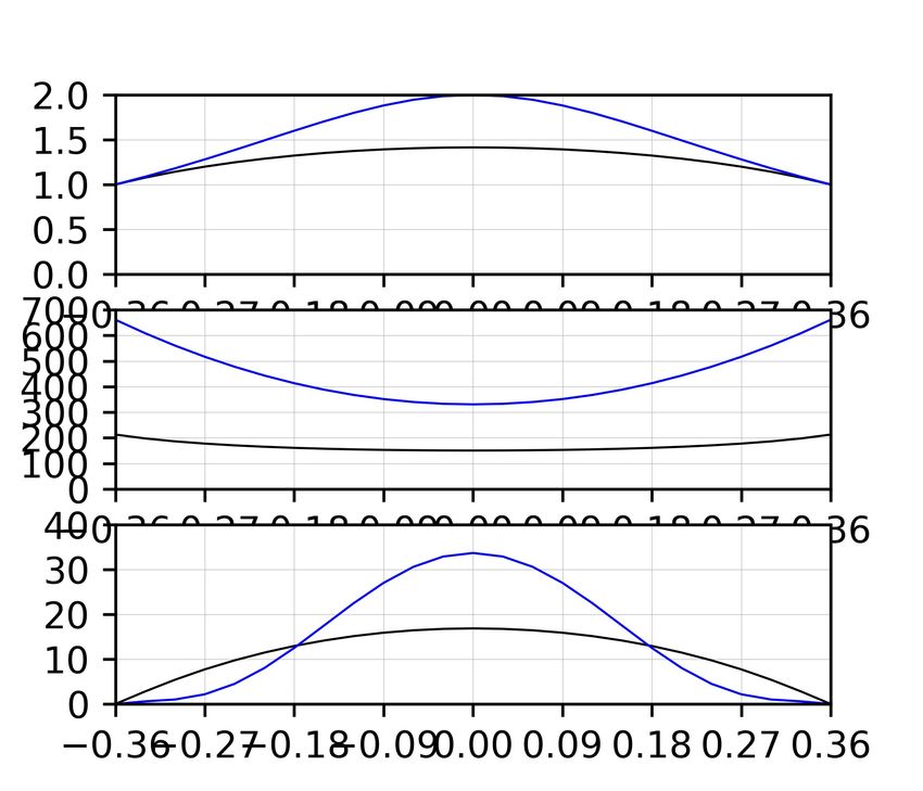
m1 m15 m1 m15
(a) (b)
5
Frequency (kHz)
metabarrier energy 4
trapping
3
2
uz (a.u.) 1
m4 m4 m11
max 0
f = 1.8-2.5 kHz Γ X X Γ
0
min (c) With Metabarrier Without Metabarrier
1
bandgap
metabarrier
Spectrum
output Amplitude
Reduction
m11
f = 1.2-1.5 kHz
0
0 1 2 3 4 5 6
Frequency (kHz)
Figure 5. Temporal and spectral wave fields of the graded metabarrier. (a) The top and bottom insets show the displacement field filtered within the bandgaps
induced by octets with masses m4 = 11mre f (red) and m11 = 31mre f (green). (b) Evolution of the bandgap within the graded metabarrier, for masses increasing
from m1 to m15 , computed via Bloch analysis (see Methods). (c) The spectrum of a signal recorded on the right end of the metabarrier (black), in the output
point emphasized in (a), is compared with that of a receiver located at the same position in a bare lattice plate (blue). The bandgap generated by this graded
design is highlighted in gray. The amplitude reduction within the bandgap is estimated as the difference between the maximum spectrum of the two signals in
the attenuation zone, as illustrated in the figure.
at an equivalent position in a bare lattice plate in Figure 5c. The amplitude reduction, stemming from the presence of the
metawedge and approximately equal to 87%, is visibly appreciable, as well as the widening of the bandgap compared to that in
Figure 4d. Notice that, a zero-transmission range exists in both the spectra between 3.8 and 5.1 kHz, which can be attributed
to the dispersive behavior of the standard octet cells. While being progressively slowed down within the graded barrier, the
impinging energy is trapped by the bending resonant mode of the mass-strut in the octets and consequently amplified. Despite
seemingly counterproductive, this dynamic behavior underpins an effective broadband device, where wave attenuation and
energy harvesting can coexist.
Octet-based gradient index lenses
Drawing from the dynamic properties of the octet lattice, two of the most popular GRIN lenses are engineered from this
architecture to shape ray trajectories and focus wave energy. The design ofNOTES- Graded:
these devices relies on the dependency of the phase
- Source Ricker centered
velocity, extracted from the dispersion relations, upon the frequency and the tuning parameters. at 3000 this
By combining Hz relationship
- Total Bandgap between 1200 and
with the refractive index profile, the design variables of the customized octet cells are derived at different locations in the lens.
4700 Hzthe supplementary masses embedded in
Specifically, the Luneburg and Maxwell lenses are created by gradually varying
- The reduction
the octets, or the stiffness of their joints, designed to produce the required refractive between
index profile 3.5 aand
within bounded region of
4.8kHz in the signal without
radius R, which corresponds to 12 cell layers, each featured by a distinct parameter value (Figure 3c). The required theoretical
metabarrier
refractive index profile is defined as a function of the radial coordinate, r, centred is dueoftothe
in the middle the factasthat
lens, we
follows:
are inside the bandgap of the plate
made of simple octet cells without
q
nLuneburg = 2 − (r/R)2 and nMaxwell = 2/(1 + (r/R)2 ) (2)
added masses.
The effective wavespeeds in the metalenses, ve f f , and in the surrounding- lattice
Masses m1comprising
plate = 0.000002kg, onlym15 =
standard octets, v0 ,
0.000030kg. Ogni layer consiste
are retrieved from the band structure of the cells, computed via Bloch analysis, with the relationship ve f f = ω/k. di 2 In order to
eliminate their frequency dependence, originated by the dispersive nature of strati di celle
the octet, otteto
these con laare
quantities stessaevaluated at fixed
massa aggiunta.
components, f f ix . The frequencies are selected sufficiently far from the stop band, so as to prevent the waves from being
- Figure d:for
localized and amplified by the strut resonances. At 1 kHz and 5.2 kHz, respectively signal
the recorded
Luneburgat( fthe f ix,Lend ofMaxwell
) and
the metabarrier
( f f ix,M ) lens, the phase velocity is calculated for increasing added masses or node thickness and plotted in the top inset of
Figures 6b and c. While both wavespeeds feature a decreasing trend for heavier - NON SONOaCERTA
masses, SIA m14
significant drop can be observed in
the high-frequency branch ( f f ix,M ), posing as a suitable candidate for the design of a Maxwell lens, which requires an abrupt
variation of the refractive index. The opposite behavior is instead noted when varying the thickness of the nodes yielding a
8/15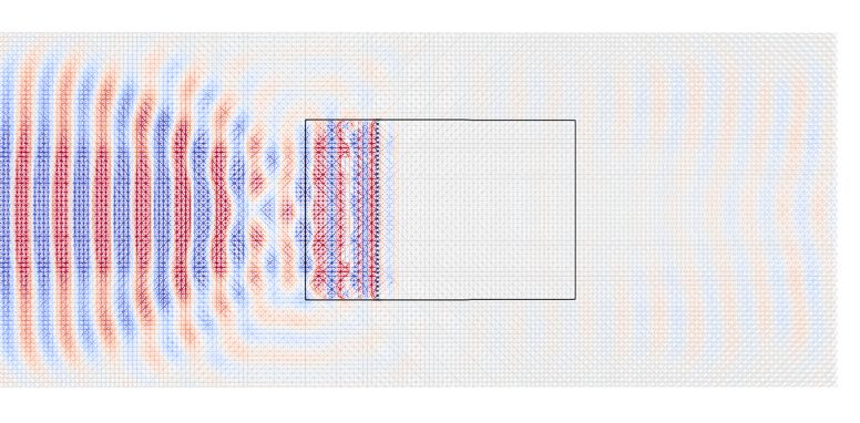
Refraction Index
2
(a)
Metalens 1
Luneburg Maxwell
0
veff r R
600 v0,Maxwell
late
veff (m/s)
a ttice P 400
L
v0,Luneburg
200
v0 0
-12l -9l -6l -3l 0 3l 6l 9l 12l
Lens r
(b) (c)
650 v0,M 650 v0,M
kHz
550 550 ffix,M = 5.2
veff (m/s )
veff (m/s )
ffix,M =
450 5.2 kH 450
z
350 350
250 v0,L ffix,L = 1 k 250 ffix,L = 1 kHz v0,L
Hz
150 150
0 4 8 12 16 20 24 28 32 0.3 0.4 0.5 0.6 0.7 0.8 0.9 1
added mass ratio (m/mref ) tnode (tstrut )
40
ratio (m/mref )
1
added mass
tnode (tstrut )
30 0.8
20 0.6
10 0.4
0 0.2
-12l -9l -6l -3l 0 3l 6l 9l 12l -12l -9l -6l -3l 0 3l 6l 9l 12l
Lens r Lens r
Figure 6. GRIN lenses design. (a) Schematic of the metalenses setup with geometry (R=0.72m) and phase velocities in the lattice plate, v0 , and metadevice,
ve f f , respectively emphasized. The right insert illustrates the index and effective velocity profiles of Luneburg (black) and Maxwell (blue) lenses as a function
of the radial coordinate, r. v0,Luneburg and v0,Maxwell are the reference velocities of waves in the base lattice plate at 1 kHz and 5.2 kHz. At r=R, ve f f = v0 . (b)
and (c) Design parameters of GRIN lenses comprising the customized octets with auxiliary masses or variable node thickness (see Figures 1c and d). The top
insert represents the variation of effective phase velocity with respect to the tuning parameter at the fixed design frequencies of Luneburg and Maxwell lenses.
The derived parameters are reported in the bottom inset.
speed-up of the waves that propagate from hinge-based (tnode = 0.3 tstrut ) to stiffer lattices (tnode = tstrut ). These findings serve
as a bridge between the theoretical profiles of GRIN lenses and their actual implementation using reticulated structures, as they
relate the octet properties to the refractive index, n, by means of the effective velocity.
After computing the refractive index profiles of the Luneburg and Maxwell lenses with the formula from Equation 2, as
shown in Figure 6a for increasing radial coordinate, the following expression for the refractive index,
v0
n(r) = , (3)
ve f f
is used to retrieve the phase velocity distributions illustrated in the bottom inset of Figure 6a. Finally, an inverse design
approach, relying on the relations in top Figures 6b and c, is adopted to identify the tuning parameters of the customized octets
at different r, based on the input effective velocity. The designed point masses and node thicknesses are outlined in Figures 6b
and c for Luneburg and Maxwell lenses. Specifically, embedded masses from 3mre f to 17mre f or node thicknesses ranging
from 0.2 to 1 tstrut are determined according to the Luneburg lens refractive index (from 1 to 1.41). The fish-eye lens, instead,
originates from a stronger variation of the index profile (from 1 to 2), which requires masses from 1 to 34mre f or tnode to vary
between 0.3 and 1 tstrut .
These designs, engineered via Bloch theory, are validated by means of time domain numerical simulations of waves
traveling in the finite plate of Figure 3a, with the Real-ESSI Simulator (see Methods). Both GRIN metalenses are obtained
9/15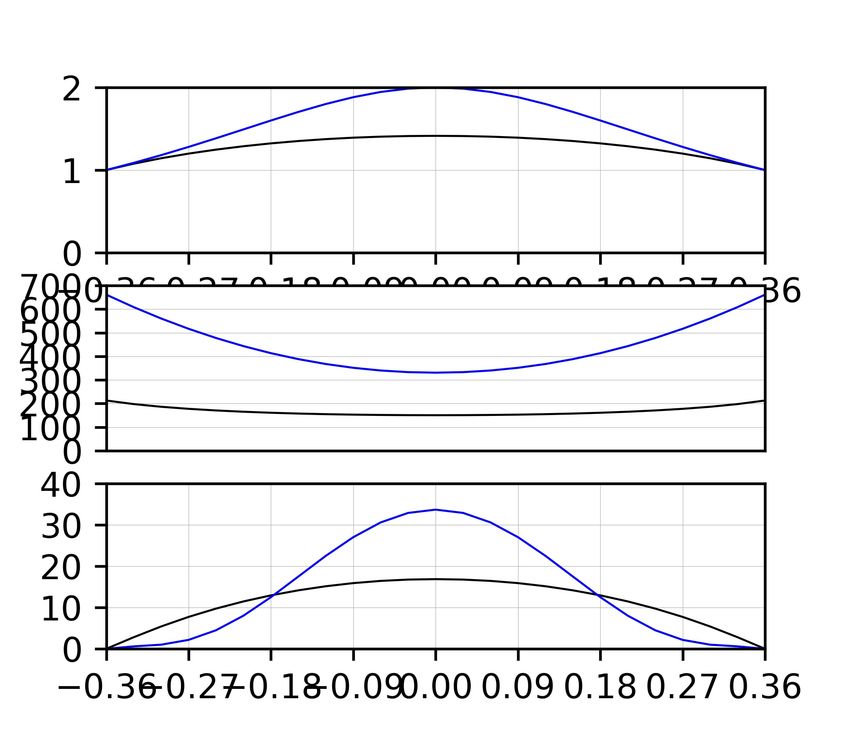
(a)
      t = 6.8 ms                                              t = 10.4 ms

                                                                                                    output points
                     Luneburg lens                                            Luneburg lens

                                                                                                                                     With lens         Without lens
  y                                                                                                                         1                         t = 10.4 ms

                                                                                                                    |uz|
        x                                                                                                                  0.5

                                           Isocurve
                                                                                                                            0
                                                                                                                             -R                                    R
                                                    ffix,L                                                                                    y (m)
                                    ky
      ffix,L = 1 kHz                                            ffix,L = 1 kHz
                                                                                                                                 uz (a.u)
                                                                                                                                   max                Source
                                               kx
                                                                                                                                   0                  Focal Point
(b)   t = 1.8 ms                                               t = 4.8 ms                                                                             Anisotropic
                                                                                                                                   min
                                                                                                                                                      Propagation

                                                                                                    output points
                    Maxwell lens                                              Maxwell lens

                                                                                                                                       With lens       Without lens
                                                                                                                            1                         t = 2.9 ms

                                                                                                                    |uz|
                                                                                                                           0.5

                                           Isocurve
                                                                                                                            0
                                                    ffix,M                                                                   -R                                     R
                                                                                                                                              y (m)
      ffix,M = 5.2 kHz              ky                          ffix,M = 5.2 kHz

                                               kx

Figure 7. Wave field snapshots in gradient-index lenses consisting of octets with embedded masses. (a) Luneburg lens (black circle) with impinging plane
sinusoidal wave of frequency f f ix,L at two consecutive instants. (b) Maxwell lens excited by a point source (red diamond) of frequency f f ix,M at two instants.
In both figures, the isofrequency contours of a standard octet-based plate within the first Brillouin zone at 1 and 5.2 kHz are depicted in the bottom right insets.
The flexural displacement recorded by a line of receivers is compared to the equivalent field in a bare plate (insets).

 by endowing the octet cells with the masses estimated in Figure 6b and are excited by sinusoidal sources tuned at the design
 frequencies f f ix,L and f f ix,M . As input signal for the Luneburg one, we use a plane wave of 40ms and 1kHz. In the Maxwell
 case we instead use a point-like source of frequency 5.2 kHz and duration 10ms. The wave field travels through the lenses with
 minimal losses and reflections, thanks to the gradual variation of properties from the plain octet lattice at r = R to the center of
 the device that minimize the impedance mismatch (see videos in the Supplementary Material). In Figure 7a, a plane wave
 impinging on the left side of the Luneburg lens at 6.8 ms is progressively bent by the smooth refractive index transition and
 its trajectory is steered toward a diametrically opposite focal point placed on its surface (t=10.4ms). An array of receivers,
 positioned along this edge, outlines the significant energy localization generated by the lens. A sharp spike emerges in the
 out-of-plane displacement uz and its peak value is almost twice as large as its counterpart on the bare plate.
      Similarly, two distinct time instants in Figure 7b validate the Maxwell lens design, where the wave originating from a point
 source located at the leftmost side of the lens is guided toward an antipodal focus thus, creating the typical fish-eye effect.
 Notice that, a non-circular wavefront is produced by the fields of the source and focal point in the surrounding plate, which
 instead propagate along preferential directions (approximately at 45°) due to the anisotropic character of the standard octet
 lattice. This behavior is further corroborated by the isofrequency contours of the standard octet lattice at f f ix,M , reported in the
 bottom inset of Figure 7b. A 70x70 plate, complemented with absorbing boundary conditions and a broadband point source
 placed at its center, is leveraged for the numerical derivation of the isocurves. The resulting wave field is spatio-temporally

                                                                                                                                                               10/15
Fourier transformed and the snapshot corresponding to 5.2 kHz is then extracted. The circular isofrequency contours, typical
of an isotropic medium, distort here to a rhombic shape emphasizing the anisotropic nature of the lattice. The wave vectors
impinging any of these contours are transmitted along the diagonals of the first Brillouin zone, causing the wave field in the
real space to assume the cross-like form that emerges in Figure 7b. A similar anisotropic trait can be appreciated at lower
frequencies ( f f ix,L =1 kHz) upon inspection of the corresponding isofrequecy contour (bottom inset of Figure 7a). In addition,
the anisotropy explains the near-zero vertical displacement in the receivers of the bare plate, blue curve in the inset of Figure 7b,
which juxtaposes with the peak of the highly focused signal from the lens (black line). Equivalent results are obtained when the
lens design is based on the variation of the node thickness. The only difference lies in the shape of the metadevice, squared
instead of circular, to avoid discontinuities in the boundary conditions of the struts.
Discussion
We have demonstrated the potential of octet-based lattice plates in controlling the trajectories of asymmetric Lamb-like waves,
be it via attenuation or wave guiding. Starting from the cellular architecture of this structure, we prove the standard octet unit is
capable of supporting a Fano-type bandgap (3.85-5.08 kHz) induced by the coalescence of local bending resonances and Bragg
frequency, opening the avenue for an easy-to-tune, single-phase material in elastic applications. The design of this woven
structure is simplified by viewing the struts as Euler-Bernoulli beams clamped at both their ends and leveraging the analytical
expression of the fundamental flexural mode as a prediction paradigm for the bandgap opening frequency; furthermore, since
the octet contains struts of length and direction identical to that of the primitive lattice vectors, it creates a medium in which the
clamped-clamped fundamental resonance exists as a standing wave between nodes, hence it is a medium in which local bending
resonances and Bragg frequencies coincide, resulting in destructive interferences and a broadband resonant based bandgap.
The two tuning parameters extrapolated from this analogy, midpoint added masses and joint thickness, are proven to control
the frequency content of the attenuation zone as well as the slope of the low and high-frequency bands exhibiting out-of-plane
polarization. The opening frequency of the bandgap is inversely correlated with the masses and directly correlated with the
node thickness; heavier masses drive the forbidden range to lower frequencies and reduce the phase velocity of waves in the
lattice, conversely, thicker nodes shift the content of the attenuation zone to higher values and privilege the transmission of
faster waves.
Drawing from these intrinsic dynamic behaviors, four devices for controlling ray trajectories are successfully engineered.
The devices operate over a range of scales, the metabarriers leverage the bandgap and hence operate within a Bragg-scattering
regime; on the other hand, the Luneburg lens is based on spatial variations of the low-frequency A0 mode and hence the
underlying octet cells behave in a subwavelength manner.
The constant metabarrier confirms the existence of a hybridization bandgap (1.8-2.8 kHz) stemming from the interaction
between the propagating flexural field and octet units equipped with auxiliary masses. The wave impinging the resonant
members is backscattered and prevented from being transmitted within the metastructure. Whilst the bandwidth of the constant
metabarrier is broad, the bandgap and frequency range is spatially localized; we introduce a graded design capable of, not
only tripling the mitigation width (1.14-5.1 kHz), but also spatially filtering the spectrum via a rainbow trapping mechanism,
amplifying a large spectrum of frequencies within its resonating struts. The generating mechanism of the stop band, initially
exploited by the lattice metabarriers to match the frequency content of incoming fields and inhibit them, serves to also tune the
phase velocity within a bounded region and enable wave steering. Two GRIN lenses, the Luneburg and Maxwell fish-eye, are
successfully implemented by gradually adjusting the properties of the customized octets according to the theoretical index
spatial distribution, thus paving the way for novel applications of this face-centered cubic topology in wave focusing.
Although the dynamic assessment of three-dimensional woven lattices is still at a primordial stage compared to the existing
knowledge on their static mechanical properties, the outcomes of our work have shed light on the hidden potential of the octet
and tuning parameters. The ease of scaling to different wavelengths that characterizes this structure renders it even more
attractive for applications in a variety of domains, including vibration isolation or conversion of focused energy. Indeed, the
vibration energy trapped and focused, respectively by the struts and metalenses, could be harvested and converted into other
forms of energy, e.g., electrical, by attaching piezoeletric components to the lattice. Future steps could, for instance, address
the complicated matter of stress concentration due to dynamic loading, as well as the experimental validation of the proposed
structures or the extension to different lattice unit cell based both on struts and sheets such as foams.
Methods
Bloch Analysis. The dispersion relation, reported in Figure 2a (red dotted line), is solved using the finite element method,
performed by the software COMSOL Multiphysicsr , by sweeping through the required wavevector k determining the permitted
frequencies ω = ω(k) as an eigenvalue and the displacement field as an eigenvector. Our choice of fundamental cell (Figure
1a) is a conventional cubic-like unit cell over a primitive one15 , which allows us to align the base vectors with the propagation
11/15direction of interest. This makes the comparison between the band structure stemming from the FFT analysis performed on the
time-transient finite lattice section (Figure 1b) and the eigenmodal analysis straightforward as we only know the displacement
fields along the beams and not everywhere in the cell. With this choice of unit cell the ends of the struts either correspond to a
node point or lie on the edges of the cell, we apply either continuity conditions or quasi-periodic Bloch conditions at the strut
ends as appropriate; hence the displacement field takes the following well known form:
u(x) = U(x)e2πi(k·x−ωt) , (4)
where k = κx ex + κy ey + 0ez denotes the in-plane Bloch wavevector, ω the frequency assuming harmonic time-dependence and
U(x) is a periodic function satisfying:
U(x + na1 + ma2 ) = U(x), (5)
for any integers n and m. We restrict our attention to waves propagating along the x-axis, hence consider only k along the Γ-X
portion of the irreducible Brillouin zone (0 - 2l1 1/m). The struts are modeled as EB beams with 6 degrees of freedom in each
node (inset in Figure 1a), reducing the high computational cost of the simulations that would arise when using solid elements.
The EB theory was selected over Timoshenko theory upon fulfilling the condition EI/0.88AGlstrut24. Brillouin, L. Wave propagation in periodic structures: electric filters and crystal lattices, vol. 2 (Dover publications, 1953).
5. Simon, S. H. The Oxford solid state basics (Oxford University Press, Oxford, UK, 2013).
6. Delpero, T., Schoenwald, S., Zemp, A. & Bergamini, A. Structural engineering of three-dimensional phononic crystals. J.
Sound Vib. 363, 156–165 (2016).
7. Kaina, N., Fink, M. & Lerosey, G. Composite media mixing bragg and local resonances for highly attenuating and broad
bandgaps. Sci. reports 3, 1–7 (2013).
8. Taubert, R., Dregely, D., Stroucken, T., Christ, A. & Giessen, H. Octave-wide photonic band gap in three-dimensional
plasmonic bragg structures and limitations of radiative coupling. Nat. communications 3, 1–6 (2012).
9. Goldberg, D. et al. Exciton-lattice polaritons in multiple-quantum-well-based photonic crystals. Nat. Photonics 3, 662–666
(2009).
10. Gonella, S., To, A. C. & Liu, W. K. Interplay between phononic bandgaps and piezoelectric microstructures for energy
harvesting. J. Mech. Phys. Solids 57, 621–633 (2009).
11. Liebold-Ribeiro, Y. & Körner, C. Phononic band gaps in periodic cellular materials. Adv. Eng. Mater. 16, 328–334 (2014).
12. Junyi, L. & Balint, D. A parametric study of the mechanical and dispersion properties of cubic lattice structures. Int. J.
Solids Struct. 91, 55–71 (2016).
13. Li, Y., Baker, E., Reissman, T., Sun, C. & Liu, W. K. Design of mechanical metamaterials for simultaneous vibration
isolation and energy harvesting. Appl. Phys. Lett. 111, 251903 (2017).
14. An, X., Lai, C., Fan, H. & Zhang, C. 3D acoustic metamaterial-based mechanical metalattice structures for low-frequency
and broadband vibration attenuation. Int. J. Solids Struct. 191, 293–306 (2020).
15. Ashcroft, N. W. & Mermin, N. D. Solid State Physics (Holt-Saunders, 1976).
16. Deshpande, V. S., Fleck, N. A. & Ashby, M. F. Effective properties of the octet-truss lattice material. J. Mech. Phys. Solids
49, 1747–1769 (2001).
17. Ashby, M. F. Cellular solids–scaling of properties. Cell. Ceram. Struct. Manuf. Prop. Appl. 1–17 (2005).
18. Arya, M. & Steeves, C. A. Bandgaps in octet truss lattices. In Proceedings of the 23rd Canadian Congress on Applied
Mechanics, 471–474 (Vancouver, Canada, 2011).
19. Gerard, N. J. et al. Three-dimensional trampolinelike behavior in an ultralight elastic metamaterial. Phys. Rev. Appl. 16,
024015 (2021).
20. Chen, Y. & Wang, L. Periodic co-continuous acoustic metamaterials with overlapping locally resonant and Bragg band
gaps. Appl. Phys. Lett. 105, 191907 (2014).
21. Arretche, I. & Matlack, K. H. On the interrelationship between static and vibration mitigation properties of architected
metastructures. Front. Mater. 5, 68 (2018).
22. Lamb, H. On waves in an elastic plate. Proc. Royal Soc. London. Ser. A, Containing papers a mathematical physical
character 93, 114–128 (1917).
23. Graff, K. F. Wave Motion in Elastic Solids (Courier Corporation, 2012).
24. Colombi, A., Colquitt, D., Roux, P., Guenneau, S. & Craster, R. V. A seismic metamaterial: The resonant metawedge. Sci.
reports 6, 1–6 (2016).
25. Rupin, M., Lemoult, F., Lerosey, G. & Roux, P. Experimental demonstration of ordered and disordered multiresonant
metamaterials for lamb waves. Phys. review letters 112, 234301 (2014).
26. Colombi, A. et al. Elastic wave control beyond band-gaps: shaping the flow of waves in plates and half-spaces with
subwavelength resonant rods. Front. Mech. Eng. 3, 10 (2017).
27. Tsakmakidis, K. L., Boardman, A. D. & Hess, O. ‘Trapped rainbow’ storage of light in metamaterials. Nature 450,
397–401 (2007).
28. De Ponti, J. M. et al. Graded elastic metasurface for enhanced energy harvesting. New J. Phys. 22, 013013 (2020).
29. Liu, Y., Sun, X.-Z., Jiang, W.-Z. & Gu, Y. Tuning of bandgap structures in three-dimensional Kagome-sphere lattice. J.
Vib. Acoust. 136 (2014).
30. Maxwell, J. Solutions of problems (prob. 3, vol. viii. p. 188). The Camb. Dublin Math. J. 9, 9–11 (1854).
31. Luneburg, R. K. Mathematical Theory of Optics (Providence, Rhode Island: Brown University, 1944).
13/1532. Climente, A., Torrent, D. & Sánchez-Dehesa, J. Gradient index lenses for flexural waves based on thickness variations.
Appl. Phys. Lett. 105, 064101 (2014).
33. Tol, S., Degertekin, F. & Erturk, A. Phononic crystal Luneburg lens for omnidirectional elastic wave focusing and energy
harvesting. Appl. Phys. Lett. 111, 013503 (2017).
34. Lee, D., Cho, C., Mun, J., Park, N. & Rho, J. Demonstration of steering acoustic waves by generalized Eaton lens. Appl.
Phys. Lett. 113, 161904 (2018).
35. Park, C. M. & Lee, S. H. Acoustic luneburg lens using orifice-type metamaterial unit cells. Appl. physics letters 112,
074101 (2018).
36. Colombi, A. Resonant metalenses for flexural waves in plates. The J. Acoust. Soc. Am. 140, EL423 (2016).
37. Zhu, R. et al. Bifunctional acoustic metamaterial lens designed with coordinate transformation. Appl. Phys. Lett. 110,
113503 (2017).
38. Fuentes-Domínguez, R. et al. Design of a resonant Luneburg lens for surface acoustic waves. Ultrasonics 111, 106306
(2021).
39. Colombi, A., Guenneau, S., Roux, P. & Craster, R. V. Transformation seismology: composite soil lenses for steering
surface elastic Rayleigh waves. Sci. reports 6, 1–9 (2016).
40. Ruzzene, M., Scarpa, F. & Soranna, F. Wave beaming effects in two-dimensional cellular structures. Smart materials
structures 12, 363 (2003).
41. Casadei, F. & Rimoli, J. Anisotropy-induced broadband stress wave steering in periodic lattices. Int. J. Solids Struct. 50,
1402–1414 (2013).
42. Pal, R. K., Rimoli, J. & Ruzzene, M. Effect of large deformation pre-loads on the wave properties of hexagonal lattices.
Smart Mater. Struct. 25, 054010 (2016).
43. Zelhofer, A. J. & Kochmann, D. M. On acoustic wave beaming in two-dimensional structural lattices. Int. J. Solids Struct.
115, 248–269 (2017).
44. Xie, Y. et al. Acoustic imaging with metamaterial Luneburg lenses. Sci. reports 8, 1–6 (2018).
45. Zhao, L. et al. Ultrasound beam steering with flattened acoustic metamaterial Luneburg lens. Appl. Phys. Lett. 116, 071902
(2020).
46. Bayat, A. & Gaitanaros, S. Wave directionality in three-dimensional periodic lattices. J. Appl. Mech. 85, 011004 (2018).
47. Pennec, Y., Djafari-Rouhani, B., Larabi, H., Vasseur, J. & Hladky-Hennion, A. Low-frequency gaps in a phononic crystal
constituted of cylindrical dots deposited on a thin homogeneous plate. Phys. Rev. B 78, 104105 (2008).
48. Goffaux, C. et al. Evidence of Fano-like interference phenomena in locally resonant materials. Phys. review letters 88,
225502 (2002).
49. Wang, P., Casadei, F., Kang, S. H. & Bertoldi, K. Locally resonant band gaps in periodic beam lattices by tuning
connectivity. Phys. Rev. B 91, 020103 (2015).
50. Nolde, E., Craster, R. & Kaplunov, J. High frequency homogenization for structural mechanics. J. Mech. Phys. Solids 59,
651–671 (2011).
51. Aguzzi, G., Colombi, A., Dertimanis, V. K. & Chatzi, E. Metamaterials for groundborne vibration absorption in pillars. In
Proceedings of ISMA2020 including USD2020, 355 (KU Leuven, 2020).
52. Low, K. Closed-form formulas for fundamental vibration frequency of beams under off-centre load. J. sound vibration
201, 528–533 (1997).
53. Rajagopal, P., Drozdz, M., Skelton, E. A., Lowe, M. J. & Craster, R. V. On the use of absorbing layers to simulate the
propagation of elastic waves in unbounded isotropic media using commercially available finite element packages. Ndt & e
international 51, 30–40 (2012).
54. Miroshnichenko, A. E., Flach, S. & Kivshar, Y. S. Fano resonances in nanoscale structures. Rev. Mod. Phys. 82, 2257
(2010).
55. Lemoult, F., Kaina, N., Fink, M. & Lerosey, G. Wave propagation control at the deep subwavelength scale in metamaterials.
Nat. Phys. 9, 55–60 (2013).
56. Zaccherini, R. et al. Locally resonant metasurfaces for shear waves in granular media. Phys. Rev. Appl. 13, 034055 (2020).
14/15You can also read