Separating 39Ar from 40Ar by cryogenic distillation with Aria for dark matter searches
←
→
Page content transcription
If your browser does not render page correctly, please read the page content below
Noname manuscript No.
                                                    (will be inserted by the editor)

                                                   Separating 39Ar from 40Ar by cryogenic distillation with Aria for dark
                                                   matter searches
                                                   The DarkSide-20k Collaborationa,1
                                                   1 See   back for author list
arXiv:2101.08686v2 [physics.ins-det] 23 Jan 2021

                                                   January 26, 2021

                                                   Abstract The Aria project consists of a plant, hosting a         (UAr), with a highly suppressed content of 39Ar, is there-
                                                   350 m cryogenic isotopic distillation column, the tallest ever   fore pivotal for the physics potential of dark matter search
                                                   built, which is currently in the installation phase in a mine    experiments.
                                                   shaft at Carbosulcis S.p.A., Nuraxi-Figus (SU), Italy. Aria is        The DarkSide-50 experiment, a liquid argon time projec-
                                                   one of the pillars of the argon dark-matter search experimen-    tion chamber (LAr TPC) at Laboratori Nazionali del Gran
                                                   tal program, lead by the Global Argon Dark Matter Collab-        Sasso (LNGS), used a 150 kg active mass of UAr extracted
                                                   oration. Aria was designed to reduce the isotopic abundance      from CO2 wells in Cortez, CO, USA, and measured the 39Ar
                                                   of 39Ar, a β -emitter of cosmogenic origin, whose activity       Depletion Factor (DF) with respect to AAr to be 1400 ±
                                                   poses background and pile-up concerns in the detectors, in       200 [2]. A new production chain, that was recently set up to
                                                   the argon used for the dark-matter searches, the so-called       significantly increase the production of UAr. This new pro-
                                                   Underground Argon (UAr). In this paper, we discuss the re-       duction needs to meet the target requirements of the Global
                                                   quirements, design, construction, tests, and projected per-      Argon Dark Matter Collaboration (GADMC), a worldwide
                                                   formance of the plant for the isotopic cryogenic distillation    effort that unifies the DarkSide, DEAP-3600, MiniCLEAN,
                                                   of argon. We also present the successful results of isotopic     and ArDM experimental groups, for the construction of new
                                                   cryogenic distillation of nitrogen with a prototype plant, op-   experiments for argon dark-matter searches. In order of in-
                                                   erating the column at total reflux.                              creasing size, these new experiments are a potential Dark-
                                                                                                                    SideLowMass, with approximately 1 t target, optimized for
                                                                                                                    the detection of low-mass dark matter, aiming at improving
                                                   1 Introduction                                                   the world-leading results of the DarkSide-50 experiment [4,
                                                                                                                    5], the 51.1 t target mass DarkSide-20k [6], under construc-
                                                   Large liquid argon detectors offer one of the best avenues       tion at LNGS, Italy, and the prospected Argo, of 400 t tar-
                                                   for detecting galactic Weakly Interacting Massive Particles      get mass, that will push the experimental sensitivity down
                                                   (WIMPs) via their scattering on atomic nuclei. However, at-      to the so-called neutrino floor. The argon procurement for
                                                   mospheric argon (AAr) has a naturally occurring radioactive      this new production chain starts from the Urania plant, now
                                                   isotope, 39Ar, of isotopic abundance of 8 × 10⁻¹⁶ in mass,       in the construction phase in Cortez, CO, USA, that will ex-
                                                   which is a β -emitter of cosmogenic origin, and whose ac-        tract and purify UAr at a maximum production rate of about
                                                   tivity of about 1 Bq/kg raises background and pile-up con-       330 kg/d. The 39Ar radioactivity of UAr, though remarkably
                                                   cerns. Indeed, the liquid argon target allows for powerful       lower than that of AAr, is neither low enough for the needs
                                                   discrimination between nuclear and electron recoil scintilla-    of the DarkSide-LowMass experiment, where it would be
                                                   tion signals via pulse-shape discrimination [1–3], provided      the limiting background to the cross-section sensitivity, nor
                                                   the background rate is not too high. However, this discrimi-     for the Argo experiment, where it would cause a major event
                                                   nation method cannot be applied in experiments that look at      pile-up, if built with the double-phase TPC technology.
                                                   the ionization signal only [4, 5]. The use of argon extracted         The cryogenic isotopic distillation plant Aria, which is
                                                   from underground wells, the so-called Underground Argon          currently in the installation phase in a mine shaft at Carbo-
                                                                                                                    Sulcis S.p.A., in Nuraxi-Figus (SU), Italy, was designed to
                                                   a e-mail:   ds-ed@lngs.infn.it                                   further reduce the 39Ar isotopic fraction of the UAr by an-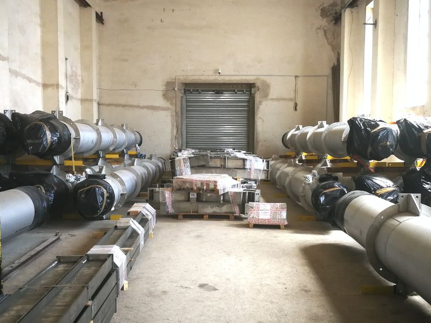
2

other factor of 10 per pass, with a production rate of several     called reboiler, that vaporizes the liquid, and extracted from
kg/d. While the 350 m tall, 31.8 cm inner diameter, distilla-      a top heat exchanger, in the so-called condenser, that con-
tion column under construction fits the needs of DarkSide-         denses the vapor. To perform the isotopic separation, the col-
LowMass in terms of production rate, for the larger Argo           umn temperature ranges between the boiling point of 40Ar
experiment a new wider column would need to be built.              (bottom) and of 39Ar (top) at the operating pressure, slightly
     Cryogenic isotopic distillation with rectifying columns       above 1 bar. The pre-cooled UAr feed enters the column at
is a well established technique [7] and has received quite         a given height and flow. The vapor rises in the column and
some attention in the context of the stable isotope separa-        re-condenses, while the liquid sinks by gravity and then re-
tion of the main biogenic elements such as carbon and oxy-         boils. In the rectifying section (above the feed point), the
gen and some industrial-scale plants have already been built.      molar fraction of 39Ar is larger than in the feed argon, while
However, for argon isotopic distillation, this is the first time   in the stripping section (below the feed point) it is smaller
that such a plant is proposed and constructed. In addition to      than in the feed argon. Liquid argon depleted of 39Ar is
cryogenic distillation, a few other techniques are currently       then collected continuously from the bottom of the column,
available for the separation of argon isotopes, based on the       whereas argon enriched of 39Ar is collected from the top.
difference in molecular mass, such as centrifugal separation       Since the 39Ar has a very low isotopic fraction even in at-
and diffusion separation, the latter based on the different av-    mospheric argon, its volatility relative to the other argon
erage speed, at thermal equilibrium, among isotopes of the         isotopes was never measured. Therefore, for the column de-
same energy. However, their application is limited by the          sign, the relative volatility of 39Ar to 40Ar, or its more com-
low yield and the high cost per unit mass of separated iso-        monly used natural logarithm, ln(α39−40 ), was derived from
topes. As a matter of fact, the cryogenic isotopic distillation    the measured relative volatility of 36Ar to 40Ar, which is
plant Aria appears as a very promising new avenue for the          0.0060 ± 0.0001 [12], at the mean operating temperature of
depletion from 39Ar of such large quantities of argon, at rea-     the column of 89.5 K, as shown in Sect. 3. According to
sonable cost and time. It is interesting to note that target pu-   the model of [13], the dependence of ln(αA−40 ) on the iso-
rification via distillation, though not isotopic, with cryogenic   topic mass A is ln(αA−40 ) ∝ (40 − A)/A. This means that,
columns in the context of dark matter search detectors was         at 89.5 K, ln(α39−40 ) is about 0.0014 and α39−40 is about
also pursued by other collaborations using xenon [8–11].           1.0014, which is the value assumed for all the calculations
     The technological capability to achieve efficient isotopic    in this paper. The uncertainty coming from model extrapola-
separation with cryogenic distillation allows to widen the         tion is however difficult to estimate and therefore this num-
application of the Aria project to other fields, where the pro-    ber should be taken as an approximate value. The tempera-
duction of stable isotopes is required, such as e.g. in med-       ture dependence of α39−40 turns out to be about -0.00005/K.
ical applications. However, in this paper we will focus on             The relative volatility of two species provides an esti-
the application of the Aria plant to the isotopic distillation     mate of how difficult it is to separate two species. Since
of argon.                                                          this ratio is close to 1 for 39Ar and 40Ar, the separation
     A very important achievement for this project was a ni-       is expected to be very difficult. To optimize the distillation
trogen distillation run of the prototype plant, a short ver-       process, the Aria column makes use of a high performance
sion of the Aria column using only the reboiler, the con-          packing material instead of the distillation trays. The two re-
denser and one central module, together with all the aux-          lated quantities that characterize the separation capability of
iliary equipment of the full column, installed in a surface        distillation columns are the number of equivalent theoretical
building. The successful outcome of this run paved the way         trays, NT , (in a distillation columns the N theoretical stages
to the continuation of the project and the construction of the     consist of the NT theoretical trays with the eventual addition
full plant.                                                        of the reboiler and the condenser, in the case they represent
                                                                   equilibrium stages) and the Height Equivalent to a Theoret-
2 Design requirements                                              ical Plate, HETP, the product of the two yielding the total
                                                                   column height.
Isotopic separation by cryogenic distillation exploits the rel-        In the Aria distillation column, for a binary mixture, the
ative volatility of different isotopes, namely, for ideal mix-     minimum number of theoretical stages needed, Nmin , at total
tures, the ratio of their vapor pressures at a given tempera-      reflux is given by the Fenske equation [14]:
ture. Continuous distillation, with a large number of distil-
lation stages, where the liquid and vapor phases undergo a
countercurrent exchange at thermodynamic equilibrium, is
used to optimize the separation of isotopes that have relative
volatility close to unity. As detailed in Sect. 3, heat is con-                 0
                                                                            ln(S39−40 )
stantly provided from a bottom heat exchanger, in the so-          Nmin =               ,                                     (1)
                                                                            ln(α39−40 )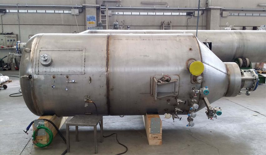
3

                   0
for a separation, S39−40 :                                        and then from Aria to LNGS, Italy, inside gas skids. The
                                                                  argon gas from the Feed Skid is fed into the distillation
 0           xD 1 − xB  xD
S39−40 =               ∼ ,                                 (2)    column through a flow controller, and pressure-regulated to
           1 − xD xB    xB
                                                                  about 1 bar. A heat exchanger (HE4) with the output dis-
where xD is the molar fraction of 39Ar in the top, xB the         tillate stream is used to cool the argon. The bottom stream
molar fraction of 39Ar in the bottom, and xD , xB  1.            comes out of the column as a liquid, gets heated as it passes
     Requiring for instance a separation of 10, from eq. (1) it   through an air heater (H1), compressed (C1) and then deliv-
follows that Nmin =1645. Moreover, when the column oper-          ered to the Bottom Skid. This is the argon that will be used
ates in finite reflux mode, the number of required stages is      in the experiments. At the top of the column, the distillate
larger than Nmin . To include such a large number of stages,      stream, enriched in 39Ar, is delivered to the Distillate Stor-
the column needs to be very tall and be filled with high per-     age after passing through HE4 and a compressor (C2).
formance packing, i.e. with a small HETP. Moreover, for ef-            Liquid nitrogen is used as cooling fluid in the heat ex-
ficient use of the packing, there is a limitation on the liquid   changer (HE1) of the column condenser. The nitrogen vapor
flow per unit area, usually specified by the vendor. Therefore    from the output of HE1 is heated through the heat exchanger
not only the height but also the diameter matters for sizeable    HE2 and then compressed, by a screw rotary compressor
distillate production.                                            (C3), to a pressure value between 2 bar and 4 bar. The com-
     To support such a tall column, a convenient and cheap        pressed gas, after cooling in HE2, is used as heating fluid
solution was found with its installation in an underground        in the heat exchanger (HE3) of the reboiler. The liquefied
vertical mineshaft of 5 m diameter and 350 m depth, dug in        nitrogen, after passing through a nitrogen phase separator
the 1940s, which was made available to Aria by the end of         tank (BT), is pumped by a modular reciprocating pump (P1),
the mine coal extraction cycle, at the end of 2018.               with a delivery pressure up to 100 bar, all the way up to the
     The first phase of the Aria project, which is the sub-       top of the column, and fed back to HE1. Liquid nitrogen is
ject of this paper, consists of a column of internal diameter     stored and fed into the circuit from an external 50 m3 tank.
d=31.8 cm, with 3 mm wall thickness, enclosed in a vacuum         The excess nitrogen gas from the system is fed back to the
cold box of 71.1 cm diameter, with a total height approxi-        tank, after being liquefied by four 4 kW cryogenerators (Stir-
mately equal to the mineshaft depth. The support structure        ling Cryogenics), inherited from the ICARUS experiment at
of the column in the shaft is designed in a way to allow for      LNGS.
the installation at later times of a wider column with a max-          Brazed plate heat exchangers are used for the reboiler
imum cold box diameter of 2.0 m.                                  (HE3), the condenser (HE1), and HE2. These heat exchang-
     The rest of the paper is organized as follows. In Sect. 3    ers are characterized by high heat transfer efficiency and
we discuss the plant design, followed by a description of the     limited size and are the ideal solution for this application.
column in Sect. 4. In Sect. 5 we present the column vacuum        Coil heat exchangers (H1 and HE4) are used for the inlet
leak tests. In Sect. 6 we discuss the prototype tests and the     and outlet argon flows.
validation of some characteristics of the plant with measure-          Fig. 1 reports also the values of operating pressure and
ments, and in Sect. 7 the projected performance of Aria for       temperature, for 39Ar- 40Ar distillation, obtained with a plant
argon isotopic distillation.                                      engineering simulation using the Aspen HYSYS package. It
                                                                  can be seen that the column operating temperature varies
3 Plant design                                                    from the top to the bottom between 87.8 K and 90.9 K.

The Aria plant simplified scheme is displayed in Fig. 1. The
column, cryogenic tanks, and heat exchangers are enclosed         4 Column and cold box structure
in a cold box (grayed area) which is vacuum-tight and de-
signed to reduce thermal losses. The cryogenic circuit of         For construction and transport, both the column and the sur-
the plant is designed with two independent loops: the argon       rounding cold box have a modular structure. The thirty mod-
loop (dark green lines for the liquid and light green lines       ules were assembled at the production site. The 28 central
for the vapor/gas) and the refrigeration loop, with nitrogen      modules are identical cylindrical elements about 12 m tall,
gas (cyan lines) and liquid (dark blue lines) that are used to    with a 71.1 cm diameter and an approximate weight of 3 t.
evaporate and to condense the argon. The Aria plant was de-       The top module, about 9.5 m tall and 1.2 m diameter, hosts
signed in a way that minimizes nitrogen consumption and           the top of the distillation column, about 1 m high, the con-
optimizes energy efficiency, by using a closed-loop refriger-     denser (HE1), a liquid nitrogen buffer tank, not shown in the
ation circuit and appropriate use of heat exchangers.             simplified scheme of Fig. 1, and two heat recovery exchang-
    UAr will be transported from the Urania plant being con-      ers (HE4 and HE2). The bottom module, about 4 m tall and
structed in Cortez, Colorado, USA, to Aria in Sardinia, Italy,    1.5 m diameter, hosts the bottom of the distillation column,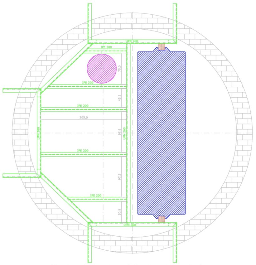
4
Fig. 1 Simplified scheme of the Aria plant. The full description can be found in the text. The color-coding of the heat exchangers is such that the
red section provides heat to the fluid while the blue section removes heat from it. The scheme also reports the values of operating pressure and
temperature for 39Ar- 40Ar distillation, as obtained from a plant engineering simulation (Aspen - HYSYS).
about 1 m high, the reboiler (HE3), and a nitrogen phase sep- ence of bellows, the support of each module is independent
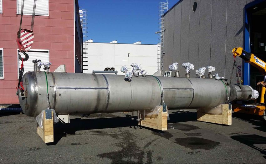
arator tank (BT). Fig. 2 shows some of the central modules from the others. The load is distributed laterally to the shaft
stored at the Carbosulcis site, ready for installation in the walls. Every module is supplied with anchor points, whose
shaft. Fig. 3 displays the top module while Fig. 4 shows the sizing takes into consideration both the static weight and the
bottom module. stresses due to the cold box operating pressure. The anchor
points are bolted to a structure, discussed in Sect. 4.3, which
The structure of the cold box, the internal equipment,
is fixed to the lateral wall of the shaft.
and the piping are fully welded to reduce the risk of leaks.
All weldings were performed at the manufacturing company
where the modules were assembled, except for the orbital
4.1 Internal structure
welds between modules, which will be performed in the mi-
neshaft.
The 28 central modules are filled with a structured stain-
To account for the thermal contraction of the structure, less steel packing (Sulzer CY gauze). To stay below the
axial bellows are interleaved between every other module. flooding limit and, therefore, guarantee an efficient distil-
At cold, the bellows expands by about 3 cm. Due to the pres- lation with this packing, according to measurements per-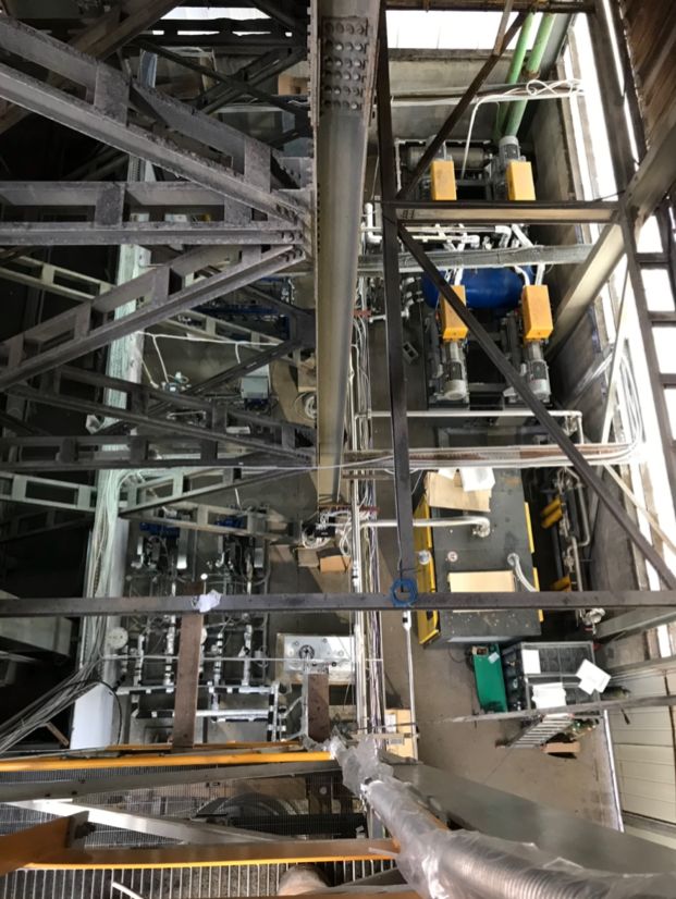
5

Fig. 2 The central modules of the column stored at Carbosulcis S.p.A.,   Fig. 5 A view from above of a liquid distributor.
Nuraxi-Figus site, ready for installation.
                                                                                                                                    √
                                                                         rium, whose value for argon is given in Table 1, is 0.8 Pa.
                                                                         With this value of F, from the reference curves provided
                                                                         by the packing producer (Sulzer) and approximating to at-
                                                                         mospheric pressure, one would expect an HETP of about
                                                                         10 cm and a pressure drop of 0.7 mbar/m. The measurement
                                                                         of these parameters in the cryogenic environment is an es-
                                                                         sential step of this research, and is the main focus of the
                                                                         tests described in Sect. 6. To avoid the channeling of the
                                                                         fluid in the packing and to optimize the uniformity across
                                                                         the column section, each module is divided into four sub-
                                                                         sections of packing, with an active height of 2.56 m each,
                                                                         interleaved with a liquid distributor, shown in Fig. 5. The
Fig. 3 The top module of the column.
                                                                         liquid formed on the distributor plate is streamed, through
                                                                         holes located at 3 cm height in perforated pipes uniformly
                                                                         distributed along the plate surface, to the packing section
                                                                         below. The vapor rises towards the packing section above
                                                                         through 12.5 cm high chimneys. The total active height of
                                                                         the column is about 287 m, that corresponds to a N of 2870.
                                                                         The pressure drop along the column is about 0.7 bar, with
                                                                         0.5 bar due to the distributors. The minimum argon mass that
                                                                         needs to be in the column for efficient distillation, is largely
                                                                         dominated by the liquid component, the vapor contributing
                                                                         only to 5 % of the total. The two major contributions come
                                                                         from the distributors, 0.3 m3 , and from the wetting of the
Fig. 4 The bottom module of the column.                                  packing, the so called holdup, 1.1 m3 . The packing wettabil-
                                                                         ity was assumed for this calculation to be 5 %, as specified
                                                                         by the packing vendor. Again, its value was given for the
formed by the vendor with chlorobenzene/etilbenzene mix-                 above mentioned organic mixture and, therefore, will need
tures, a maximum specific liquid volume flow rate or load,               to be verified at the cryogenic temperatures of the column
V̂L , of 5 m3 /(h m2 ), is allowed. Given the column inner di-           with argon. The total argon mass in the column during dis-
ameter of 31.8 cm, this corresponds to a liquid volume flow              tillation, with the above mentioned assumptions, turns out to
rate, VL , of 0.4 m3 /h or to a mass flow rate of 560 kg/h.              be approximately 2.5 t.
With this load and at the average operating pressure of the                   The thermal load of the column was calculated assuming
column with argon, the sizing parameter for packed columns               the maximum liquid flow specified by the packing producer,
                     √
F, defined as UV · ρV , where UV is the superficial gas ve-              as discussed in Sect. 4. The required thermal duty for the
locity, i.e. the vapor volume flow rate, VV , per unit column            cryogenic system turns out about 25 kW, broadly given by
cross section, and ρV the vapor argon density at equilib-                the maximum liquid flow times the heat of vaporisation. The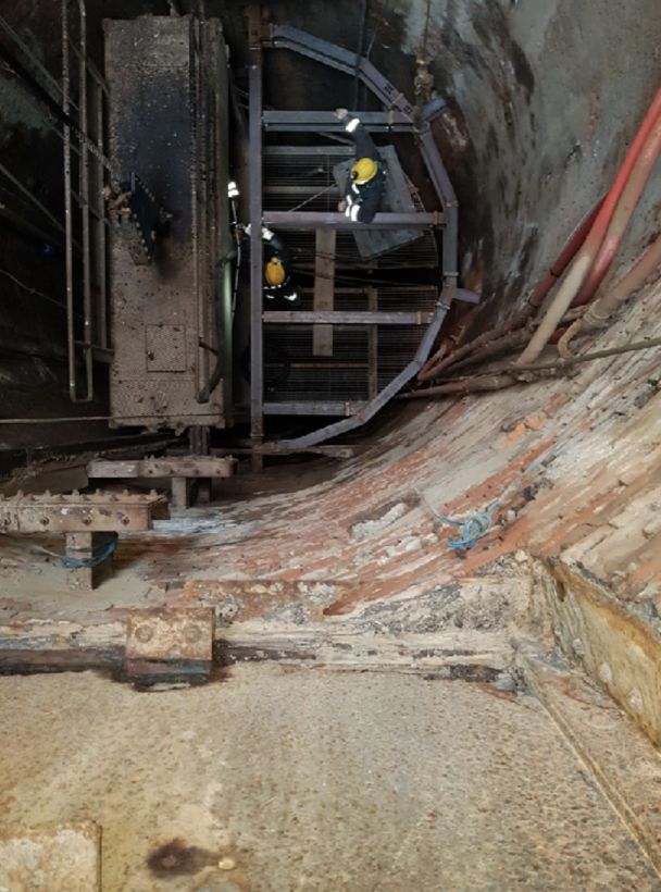
6

total electric power needed for the plant operation is about
500 kW, including the cryocooler, compressors, fluid, and
vacuum system pumps load.

4.2 Thermal insulation

To minimize heat transfer through conduction and radiation
from the environment to the cryogenic distillation column,
a 10−5 mbar vacuum is made in the cold box. In order to
maintain the desired vacuum level, several pump stations
of total pumping speed 104 L/s, are installed along the col-
umn. In addition, 20 layers of Multi-Layer Insulation (MLI)
are wrapped around the column, and 10 are wrapped around
all the other lines and reservoirs within the col box. With
this insulation, the residual thermal radiation input power to
the column is about 1 W/m2 , a few percent of the thermal
duty cycle of the column. Insulation is also provided on the
equipment and piping outside of the cold box, for minimiz-
ing heat losses and for personal protection against the risk of
injuries by accidental contacts. For cold points, the insula-
tion is based on synthetic rubber, covered with aluminum
sheets. Vacuum jacketed pipes are used for long-distance
connections.

4.3 Support structure in the shaft
                                                                   Fig. 6 Horizontal cut of the mineshaft showing the stainless steel struc-
The support structure of the column is made of austenitic          ture, in green, for positioning the column, in magenta. The blue rect-
                                                                   angle on the right is the elevator.
steel and is assembled by bolted connections. It is made of
discrete structures, shown in Fig. 6, spaced in the vertical
direction by 4 m. To keep a safety margin, three supporting        will go back and forth from room temperature down to liq-
structures per central module are foreseen, each one able, in      uid argon/nitrogen temperatures several times during their
principle, to hold the module independently. The anchoring         lifetime.
shelves penetrate the rock up to an average depth of about              An upper limit of 10−9 mbar L/s was set on the leak rate
120 cm for the central support, and 80 cm for the other two.       for each leak check performed on single modules during
For filling the 300 mm openings, a cement based thixotropic        testing, mainly on welds. Each column segment was tested
mortar is used, with high mechanical strength and compen-          twice. The first phase of tests took place at the manufactur-
sated shrinkage. Fig. 7 shows the installation of the first sup-   ing company site (Polaris Engineering), where the column
port structure in the well. Load tests were performed apply-       and the service lines were fully tested, before wrapping them
ing a 3 t load and no significant deflection was observed.         around with MLI. The second phase of the leak checks, car-
                                                                   ried out at CERN, CH, included also a full check of the cold
                                                                   box and bellows. For the tests, each module was closed tem-
5 Vacuum leak tests of individual modules                          porarily with end-caps, the space between the cold box and
                                                                   the distillation column was evacuated with a turbopump sys-
Leak detection is a critical step in the construction of Aria,     tem, and the column and the service lines were filled with a
since its functioning depends on a high cold box insulating        mixture of 90% of air and 10% of helium. In this way, the
vacuum and the distillation process should not be contam-          potential leak can be found by the leak detector associated
inated from air. For that reason, by the way, the pressure         with the turbopump system. All the modules were validated
of the process column and related lines is kept above the          in a two-step approach to confirm a leak rate smaller than
atmospheric pressure. The leak-check procedure has to be           10−9 mbar L/s on each module. Since there are 30 column
quite strict, in particular for those lines that will undergo      segments in total, the total leak rate is expected to be smaller
thermal stresses. Indeed, the column and the service lines         than 3 × 10⁻⁷ mbar L/s at room temperature. An additional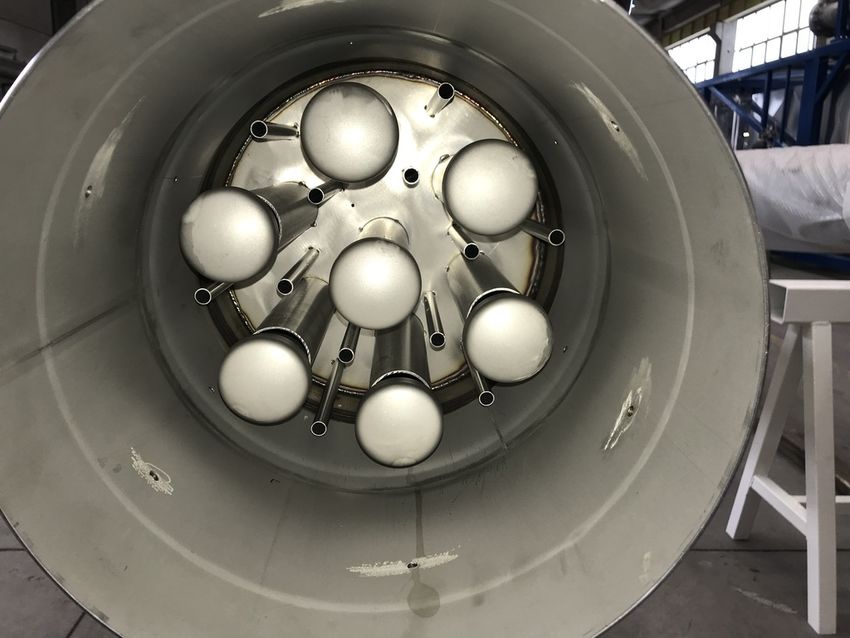
7

Fig. 7 Installation of the first support structure in the shaft of the Car-
bosulcis mine, Seruci site.

one-off leak test was performed at CERN to validate mod-
ule tightness after a thermal cycle down to 87 K. The reboiler
unit was chosen for this test, due to its complex internal weld
configuration, and tightness below 10−9 mbar L/s was again
confirmed.
                                                                              Fig. 8 The prototype Aria plant in the Laveria building of the Carbo-
                                                                              sulcis mine, Nuraxi-Figus site, viewed from the basis of the column.
6 Performance test at total reflux with a prototype
column.
                                                                              chanical support, made of galvanized and cold-painted car-
To verify the theoretical calculations about the distillation                 bon steel, consists of a square base structure with four feet
performance, and test the mechanical and cryogenic infras-                    of concrete and a modular iron pillar structure equipped on
tructure prior to column installation in the mineshaft, a pro-                each side with two diagonal support beams. The structure
totype plant was built in a surface building.                                 includes seven level platforms, to allow the presence of op-
                                                                              erators along the column height. Though self-supporting, for
                                                                              additional safety, the support is fixed to the building struc-
6.1 Prototype construction                                                    ture at two different heights.
                                                                                  After welding together the three modules, the column
The prototype plant is a short version of the Aria column                     and the four service lines were leak checked with a cali-
using only the reboiler, the condenser and one central mod-                   brated leak detector. An external calibration leak was used
ule, for a total height of 26 m, together with the auxiliary                  to estimate the helium diffusion time along all the lines. This
equipment, which is the same as that of the full column. It                   turned out to be between four and twenty seconds, depend-
is located in the Laveria building of the Carbosulcis mine,                   ing on the line. Therefore it was decided to wait at least two
Nuraxi-Figus site, as shown in Fig. 8 and Fig. 9. The me-                     minutes between every leak check to make sure that a possi-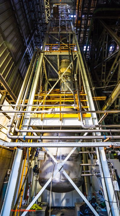
8

                                                                         6.2 Prototype Operation

                                                                         For the commissioning of the prototype plant, different pu-
                                                                         rity grades of N2 were used both in the auxiliary circuit for
                                                                         cooling, and in the process circuit for the distillation inside
                                                                         the column. The operating parameters of the auxiliary sys-
                                                                         tem were about the same as those discussed in Sect. 3.
                                                                             A dedicated slow-control system monitors and controls
                                                                         the distillation process and ll equipment in real time. This
                                                                         system uses LabVIEW (NI) as system-design platform and
                                                                         development environment, and it is organized with a dis-
                                                                         tributed layered architecture. The control cabinets are inter-
                                                                         connected by a private WLAN network, inside the Carbo-
                                                                         Sulcis network, with a Real Time Controller (NI cRIO 9039)
                                                                         reading out the data of the different expansion chassis (NI
                                                                         9049) distributed over the network. In addition, PROFIBUS,
                                                                         a standard for fieldbus communication in automation tech-
                                                                         nology, is integrated into the system to control third party
                                                                         equipment such as compressors, vacuum gauges and vac-
                                                                         uum pumps. The slow control also features advanced con-
                                                                         trols such as Proportional Integral Derivative control, cas-
                                                                         cade control, threshold logic, interlocks over valves, invert-
                                                                         ers, and temperature controllers. Historical data are stored in
                                                                         a relational data base (PostgreSQL).
                                                                             Plant operation started with feeding the cooling liquid
                                                                         nitrogen to the auxiliary circuit from the external storage
                                                                         tank and nitrogen of purity grade 5 into the column. Eight
Fig. 9 Aerial view of the prototype Aria plant located in the Laveria    hours were needed to reach the target temperature. The total
building of the Carbosulcis mine, Nuraxi-Figus site. From bottom left,   amount of nitrogen filling the column was estimated by tak-
clockwise, the liquid pumps, the cryocoolers and the gas compressor.
                                                                         ing into account that it was stored in 16 gas bottles of 50 L
                                                                         each, with an initial pressure of 200 bar and a final pressure
                                                                         of 80 bar. Using the Peng-Robinson equation of state, the
                                                                         total mass is then 110 kg.
ble signal could be associated with the precise tested weld.                 The measurements reported in this paper refer to two
The standard technique of filling sealed bags with helium                distillation runs of the plant, 165 h in total, with two differ-
around the welds was used for all the procedure. The he-                 ent screw-rotary compressor (C3) settings, with the column
lium bags, once filled with helium, were not removed un-                 operated at total reflux. The two runs started and stopped
til the last leak check. Using this method an upper limit of             with switching on and off the compressor and, with some
10−9 mbar L/s was set on all the welds between the mod-                  delay, the pumps. Fig. 10 and Fig. 11 show the measured
ules.                                                                    pressure vs. time and mass flow vs. time in the auxiliary
                                                                         system, downstream of the compressor. For these first two
    Leak detection will become increasingly more difficult               runs, an automated feedback system, foreseen in the plant
during the assembly of the modules in the shaft. With the                design, regulating the flow downstream of the compressor,
leak test procedure just described, the increased size of the            was not used. The auxiliary system gas pressure and flow
column, as the modules are assembled together, will cause                stability were guaranteed only regulating by hand a bypass
a much longer response time of the leak detection system,                valve between the compressor and the gas flow meter. A bet-
reducing its sensitivity. To overcome this difficulty, the use           ter stability was reached during the second run, where fluc-
of some new tools is foreseen. Devices called clamshells,                tuations were limited to ±0.3 bar and ±20 m3 /h, as shown
developed at CERN, will surround the welds and create a                  in Fig. 10 and Fig. 11, respectively. The pressure inside the
small sealed space that can be quickly evacuated. Helium                 column was measured by digital pressure transmitters with
will flow inside the tube/column, and the potential leak in              diaphragm seal measuring cell, located respectively below
the weld can be therefore detected with a very fast response             the first distributor from the top and right above the reboiler.
time.                                                                    Fig. 12 shows the measured pressure inside the column in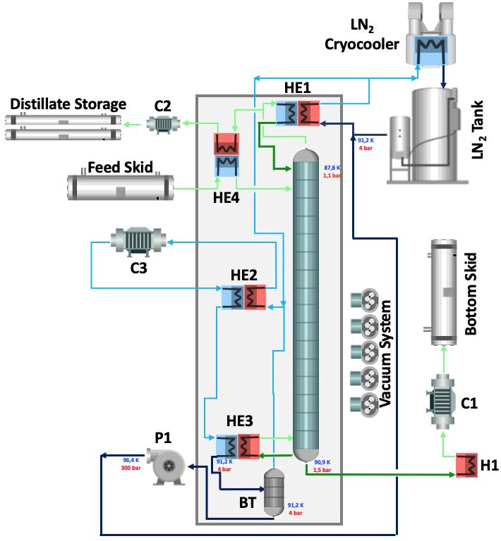
9

                                     6                                                                                      6
Pressure in auxiliary system[bar]

                                                                                           Pressure in the column[bar]
                                     5                                                                                      5

                                      4                                                                                     4

                                     3                                                                                      3

                                      2                                                                                     2

                                      1                                                                                     1

                                      0                                                                                     0
                                       0   20   40   60   80   100   120   140      160                                      0   20   40   60   80   100   120   140      160
                                                                                 Time[h]                                                                               Time[h]

Fig. 10 Measured pressure in the auxiliary system downstream of the                        Fig. 12 Measured pressure inside the column in the top vs time, for
compressor vs time, for 29N2 - 28N2 distillation in the prototype plant.                   29N - 28N distillation in the prototype plant.
                                                                                               2    2

                                    700                                                                                  100
Vapor Mass Flow[Kg/h]

                                                                                           Pressure difference [mbar]

                                                                                                                           80
                                    600
                                                                                                                           60
                                    500                                                                                    40

                                                                                                                           20
                                    400
                                                                                                                            0
                                    300
                                                                                                                          −20

                                    200                                                                                   −40

                                                                                                                          −60
                                    100
                                                                                                                          −80

                                      0                                                                                  −100
                                       0   20   40   60   80   100   120   140      160                                      0   20   40   60   80   100   120   140      160
                                                                                 Time[h]                                                                               Time[h]

Fig. 11 Measured vapor mass flow in the auxiliary system downstream                        Fig. 13 Measured pressure difference condenser vs. reboiler in the col-
of the compressor vs time, for 29N2 - 28N2 distillation in the prototype                   umn vs time, for 29N2 - 28N2 distillation in the prototype plant.
plant.

                                                                                           sured vacuum level in the cold box during the two runs was
the top vs. time. The different pressure in the column com-                                stable around 3 × 10⁻⁶ mbar.
pared to what is expected for argon, as discussed in Sect. 3,
comes from the different thermodynamic properties of the
nitrogen and the operating temperature gradients of the heat
exchangers of the reboiler and of the condenser of about 5 K.
Since nitrogen was used both for cooling and as distillation                               6.3 Expected values for nitrogen distillation
fluid, the mass flow rate in the cooling circuit was the same
as that inside the column. From Fig. 11 it can be deduced,                                 The nitrogen molecule, N2 , is mainly formed by two sta-
then, that the mass flowrates during this test ranged between                              ble isotopes, 14N and 15N, leading to an isotopic fraction
the maximum allowed flow in the column by the packing                                      of 99.3 % for the 28N2 and 0.7 % for the 29N2 , and, there-
producer, as discussed in Sect. 4, and half of it. The pressure                            fore, to an isotopic ratio, RN2 , between the two molecules, of
drop along the prototype column during the second run was                                  7.4 × 10⁻³ . The relative volatility between 29N2 and 28N2 ,
of the order of 12 mbar, as shown in Fig. 13. Therefore, for                               α28−29 , is given, according to [7], by ln α28−29 = 0.846/T -
the following calculations, it is possible to assume that both                             6.9 × 10⁻³ , where T is the temperature in Kelvin, implying
pressure and temperature are constant along the column. The                                α28−29 =1.003, at the mean column operating temperature of
nitrogen temperature inside the column was derived from                                    85 K. This value of the relative volatility is large enough to
the pressure measurement using the Antoine equation [15].                                  give a sizeable separation, at total reflux, even with the pro-
From the data of Fig. 12 it follows that, during the second                                totype column that nominally has only about 100 theoretical
run, the temperature ranged from 83 K to 87 K. The mea-                                                         0
                                                                                           stages, namely of S28−29    =1.35.
10
1 1.4
[x 10-2]
28-29
Separation S0
0.95 1.35
N2
0.9 1.3
Isotopic ratio R
0.85 1.25
0.8 1.2
0.75 1.15
0.7 1.1
0.65 1.05
0.6 1
0 20 40 60 80 100 120 140 160 0 20 40 60 80 100 120 140 160
Time[h] Time[h]
Fig. 14 Reboiler (red), condenser (blue), and feed (black), isotopic ra- 0
Fig. 15 Separation factor S28−29 for 29N - 28N distillation in the pro-
2 2
tio RN2 vs. time for 29N2 - 28N2 distillation in the prototype plant. totype plant.
.
25
HETP [cm]
20
6.4 Distillation measurements
15
A quadrupole mass spectrometer (Extrel MAX-300) mea- 10
sured the fluid composition, sampling in the reboiler, in the
condenser, and in the feed line at the output of the gas bot- 5
tles, using up to 18 m long and 0.18 mm diameter copper
capillaries. With this mass spectrometer, the peaks corre- 0
0 20 40 60 80 100 120 140 160
sponding to 28N2 and 29N2 are well separated, and, there- Time[h]
fore, isotopic ratio measurements were directly taken from Fig. 16 HETP vs. time for 29N - 28N distillation in the prototype
2 2
the peak height ratio. In Fig. 14 the measured isotopic ra- plant.
tios RN2 vs. time from the reboiler, condenser and feed are
shown. When the plant started operation, the three isotopic
ratios were the same. With time, they started to diverge, as 6.5 Measurement interpretation
expected with the distillation taking place, and, after some
time, they reached a plateau value. It should be noticed that From the measured separation S28−29 0 and the calculated re-
at the end of the first run, the isotopic ratio in the reboiler lationship between α28−29 and temperature, as discussed in
dropped almost to the feed value while the one of the con- Sect. 6.3, it is possible to derive the effective number of the-
denser increased only after about 10 h. This is due to the fact oretical stages and, knowing the packing height per mod-
that when the compressor and the pumps are switched off, ule of 10.24 m, as discussed in Sect. 4, the HETP vs. time,
i.e. the distillation process is stopped, the liquid present in as shown in Fig. 16. The best value obtained during the
the columns sinks quickly in the reboiler under gravity, and two runs is about 11.5 cm. This value of HETP is in broad
mixes with that already present there, whereas this is not the agreement with the assumed value for argon of Sect. 7. This
case for the vapor. From Fig. 14 it can also be noticed that agreement represents a validation of the concept of cryo-
the isotopic ratio of the feed gas is not exactly equal to the genic distillation with this plant. However, it should be un-
natural isotopic ratio value discussed in Sect. 6.3 and this derlined that the tests described here were performed, in
is due to the mass spectrometer not fully calibrated before terms of pressure inside the column, outside of the range for
use. Also the isotopic ratio values slightly drifted over time, which the vendor provides comparison
√ data, and at a value
probably due to some internal component of the spectrome- of the sizing parameter F of 0.3 Pa, which is different from
ter becoming dirty. Anyhow, the separation, S28−29 0 , defined that calculated for argon in Sect. 4. The observed transient,
as RN2 (condenser)/RN2 (reboiler), depending only on the ra- i.e. the time needed to reach plateau operation in Fig. 15,
tio of the two RN2 , it is not affected by this drift to first order. turns out to be about 16 h. It is important to point out that
Fig. 15 shows the separation, S28−290 , vs time. the time to reach the steady state is strongly dependent on11
Table 1 Input parameters of the Table 2 Output parameters of
parameter value parameter value
calculation of 39Ar- 40Ar distil- the calculation of 39Ar- 40Ar dis-
lation with the McCabe-Thiele tillation with the McCabe-Thiele
method. ρL is the liquid argon
xF 6 × 10⁻¹⁹ method, for B/F= 50 %. The
B 8.1 kg/d
density at equilibrium at 89.5 K xB 6 × 10⁻²⁰ various parameters are described F 15 kg/d
and xF the molar fraction of 39Ar α39−40 1.0014 in the text. R 1547
in the feed. The other parameters ρL 1380 kg/m3 xD 1.1 × 10⁻¹⁸
are described in the text.
ρV 7.1 kg/m3 S39−40 18
d 31.8 cm
N 2870
V̂L 5 m3 /(h m2 )
mark value is shown in Fig. 18. The output parameters of
the calculation are shown in Table 2. The calculation also
yields the location of the feed point in the column, which
mass flow rate B [kg/day]
turns out to be at the top of the seventh module, i.e. at about
10
20% height from the top of the column. This is where the
feed connections are located. The obtained value of S39−40 ,
8
the separation of eq. (2) calculated at finite reflux, can be
0
compared with that obtained at total reflux, S39−40 , which is
6 −20
57. If xB were required to be 3 × 10 , then B would be-
4
come 2.5 kg/d, with the same feed point.
The dominant systematic uncertainties in this calcula-
2 tion come from the uncertainty on the mean α39−40 value
and on the number of theoretical stages, N. As discussed
0
0.2 0.3 0.4 0.5 0.6 0.7 0.8 in Sect. 2, α39−40 was calculated from the measured value
B/F of α36−40 . Another publication [17] reports a lower value
Fig. 17 39Ar- 40Ar
distillation with the McCabe-Thiele method: B of α36−40 than that reported in Sect. 2, that would lead to
mass flow vs. B/F. α39−40 =1.0013 at the mean operating temperature of the col-
umn of 89.5 K. At this value one would have a decrease in B
by about 25%. A 10% variation on N leads instead to a 30%
the fluid to be distilled, the duty at the reboiler, and the num-
change in B. Were the measurements of HETP reported in
ber of theoretical stages. Further investigation is therefore
Sect. 6 confirmed in a run with argon, a decrease in B of this
required before extrapolating this value to the Aria column
magnitude, compared to that of Table 2, could be expected.
performance with argon.
Eventually, all the output rates are proportional to V̂L , i.e.
halving this value leads to halving B. The effect of varying
7 Projected performance of Aria with argon, at finite α39−40 along the column height according to the tempera-
reflux ture profile, was estimated modifying the standard McCabe-
Thiele calculation, with the equilibrium curve assumed to
The McCabe-Thiele method [16] was used to calculate the be varying stage by stage. A marginal difference in the final
performance of argon distillation in Aria with finite reflux. result was obtained.
This method was already applied to cryogenic distillation A major assumption in the above calculation is the bi-
by collaborations using xenon as active target for dark mat- nary distillation hypothesis, i.e. that isotopes present in the
ter search [8, 10, 11], but it is fair to say that it was never gas other than 39Ar and 40Ar do not influence the calcula-
validated with argon. The input parameters of the calcula- tion. It is well known that 36Ar and 38Ar have sizeable iso-
tion are summarized in Table 1 and it was also assumed the topic fractions in AAr, of 0.33% and 0.06%, respectively,
feed to be a saturated vapor. The relative volatility, α39−40 , though it has been reported that their isotopic fraction is
is assumed constant along the column height and equal to about forty times lower in UAr [18]. However, the assump-
the value corresponding to the mean operating temperature tion of a binary mixture is considered to be reasonable, for
of the column. The calculation was performed for individ- two main reasons. On one hand, the two additional isotopes
ual values of B/F, where B and F are the mass flow rates in are mostly recovered in the distillate stream, because their
the bottom and feed streams, respectively. Fig. 17 shows B relative volatility to 40Ar is larger than one, and therefore
vs. B/F. We consider as benchmark value B/F to be 50 %, a we expect no significant difference in the composition of
reasonable assumption given the UAr is a valuable material. the bottom stream. On the other hand, the isotopic fraction
The McCabe-Thiele diagram corresponding to this bench- of both the distillate and the bottom flow of 36Ar and 38Ar12
y(39Ar)
Distillate composition: (xD,x D)
− 18
10
Feed line
−18
0.602 ×10
um ng
bri fyi
li c ti
Eq
ui Rey=x
0.6
10−19
g
comp.
in
Feed
i pp
Str
0.598 ×10⁻¹⁸
0.598 0.6 0.602
Bottoms composition: (x B ,x B )
10−19 10−18 39
x( Ar)
Fig. 18 McCabe-Thiele diagram for the 39Ar- 40Ar distillation with the input parameters of Table 1, for B/F= 50 %: mole fraction of 39 Ar in the
liquid phase, y(39 Ar), vs. mole fraction of 39 Ar in the vapor phase, x(39 Ar). The insert is a blow-up of the region indicated by the shaded lines.
are anyway expected to change only by a small factor since, Table 3 McCabe-Thiele
method: output parameters
parameter value
for each isotope i,
for 36Ar- 40Ar distillation in a
run with atmospheric argon. B 45 kg/d
B · (xB )i D · (xD )i Feed, F, and bottom, B, mass F 60 kg/d
< 1 and13
8 Conclusion and outlook support from Pacific Northwest National Laboratory, which
is operated by Battelle for the U.S. Department of Energy
The design, construction, prototype tests, and performance under Contract No. DE-AC05-76RL01830.
simulations of the Aria cryogenic distillation column that is
currently in the installation phase at Carbosulcis S.p.A., in
Nuraxi-Figus (SU), Italy were discussed in detail. The mea-
surement with the prototype of a HETP in broad agreement References
with the expectations, validated the concept of the cryogenic
1. P. Agnes, T. Alexander, A.K. Alton, K. Arisaka, H.O.
distillation with this plant. The successful run of the Aria
Back, B. Baldin, K. Biery, G. Bonfini, M. Bossa,
plant is expected to have a tremendous impact in the field of
A. Brigatti et al. (DarkSide-50 Collaboration), Phys.
isotopic separation, with applications ranging from nuclear
Lett. B 743, 456 (2015)
physics to medicine and beyond.
2. P. Agnes, L. Agostino, I.F.M. Albuquerque, T. Alexan-
der, A.K. Alton, K. Arisaka, H.O. Back, B. Baldin,
Acknowledgements K. Biery, G. Bonfini et al. (DarkSide-50 Collaboration),
Phys. Rev. D 93, 081101 (2016)
The second phase of the leak checks, carried out at CERN, 3. P.A. Amaudruz, M. Baldwin, M. Batygov, B. Beltran,
was performed under service agreement KN3155/TE. We C.E. Bina, D. Bishop, J. Bonatt, G. Boorman, M.G.
acknowledge the professional contribution of the Mine and Boulay, B. Broerman et al. (DEAP-3600 Collabora-
Electrical Maintenance staff of Carbosulcis S.p.A. Part of tion), Phys. Rev. Lett. 121, 071801 (2018)
the project funding comes from Intervento finanziato con ri- 4. P. Agnes, I.F.M. Albuquerque, T. Alexander, A.K. Al-
sorse FSC 2014-2020 - Patto per lo Sviluppo della Regione ton, G.R. Araujo, D.M. Asner, M. Ave, H.O. Back,
Sardegna. This paper is based upon work supported by the B. Baldin, G. Batignani et al. (DarkSide-50 Collabora-
U. S. National Science Foundation (NSF) (Grants No. PHY- tion), Phys. Rev. Lett. 121, 081307 (2018)
0919363, No. PHY-1004054, No. PHY-1004072, No. PHY- 5. P. Agnes, I.F.M. Albuquerque, T. Alexander, A.K. Al-
1242585, No. PHY-1314483, No. PHY- 1314507, associated ton, G.R. Araujo, D.M. Asner, M. Ave, H.O. Back,
collaborative grants, No. PHY-1211308, No. PHY-1314501, B. Baldin, G. Batignani et al. (DarkSide-50 Collabora-
No. PHY-1455351 and No. PHY-1606912, as well as Ma- tion), Phys. Rev. Lett. 121, 111303 (2018)
jor Research Instrumentation Grant No. MRI-1429544), the 6. C.E. Aalseth, F. Acerbi, P. Agnes, I.F.M. Albuquerque,
Italian Istituto Nazionale di Fisica Nucleare (Grants from T. Alexander, A. Alici, A.K. Alton, P. Antonioli, S. Ar-
Italian Ministero dell’Istruzione, Università, e Ricerca ARIA celli, R. Ardito et al. (DarkSide-20k Collaboration),
e la Ricerca della Materia Oscura - Fondo Integrativo Spe- Eur. Phys. J. Plus 133, 131 (2018)
ciale per la Ricerca (FISR) and Progetto Premiale 2013 and 7. B. Andreev, E. Magomedbekov, A. Raitman,
Commissione Scientifica Nazionale II). We acknowledge the M. Pozenkevich, Y. Sakharovsky, A. Khoroshilov,
financial support by LabEx UnivEarthS (ANR-10-LABX- in Separation of Isotopes of Biogenic Elements in Two-
0023 and ANR-18-IDEX-0001), the Natural Sciences and phase Systems, edited by B. Andreev, E. Magomed-
Engineering Research Council of Canada, SNOLAB, Arthur bekov, A. Raitman, M. Pozenkevich, Y. Sakharovsky,
B. McDonald Canadian Astroparticle Physics Research In- A. Khoroshilov (Elsevier, Amsterdam, 2007)
stitute, and the São Paulo Research Foundation (Grant No. 8. Z. Wang, L. Bao, X.H. Hao, Y.L. Ju, K. Pushkin, M. He,
FAPESP - 2017/26238-4). The authors were also supported J. Instrum. 9, P11024 (2014)
by the Unidad de Excelencia María de Maeztu: CIEMAT - 9. Z. Wang, L. Bao, X. Hao, Y. Ju, Rev. Sci. Instrum. 85,
Física de partículas (Grant No. MDM 2015-0509), the Pol- 015116 (2014)
ish National Science Centre (Grant No. UMO-2019/33/B/- 10. K. Abe, J. Hosaka, T. Iida, M. Ikeda, K. Kobayashi,
ST2/02884), the Foundation for Polish Science (Grant No. Y. Koshio, A. Minamino, M. Miura, S. Moriyama,
TEAM/2016 - 2/17), the International Research Agenda Pro- M. Nakahata et al. (XMASS Collaboration), Astropart.
gram AstroCeNT (Grant No. MAB/2018/7) funded by the Phys. 31, 290 (2009)
Foundation for Polish Science from the European Regional 11. E. Aprile et al. (XENON Collaboration), Eur. Phys. J. C
Development Fund, the European Union’s Horizon 2020 re- 77, 275 (2017)
search and innovation program under grant agreement No 12. R. Fieschi, N. Terzi, Physica 27, 453 (1961)
962480, the Science and Technology Facilities Council, part 13. J.N. Canongia Lopes, A.A.H. Pádua, L.P.N. Rebelo,
of the United Kingdom Research and Innovation, and The J. Bigeleisen, J. Chem. Phys. 118, 5028 (2003)
Royal Society (United Kingdom). I.F.M.A is supported in 14. M.R. Fenske, Ind.Eng. Chem. 24, 482 (1932)
part by Conselho Nacional de Desenvolvimento Científico 15. M.P. Edejer, G. Thodos, J. Chem. Eng. Data 12, 206
e Tecnológico (CNPq). We also wish to acknowledge the (1967)14
16. W.L. McCabe, E.W. Thiele, Ind. Eng. Chem. 17, 605
(1925)
17. C.G. Boato, G, M.E. Vallauri, Nuovo Cim. 16, 505
(1959)
18. R. Saldanha, H. Back, R. Tsang, T. Alexander, S. Elliott,
S. Ferrara, E. Mace, C. Overman, M. Zalavadia, Phys.
Rev. C 100, 024608 (2019)
19. C.E. Aalseth, F. Acerbi, P. Agnes, I.F.M. Albuquerque,
T. Alexander, A. Alici, A.K. Alton, P. Antonioli, S. Ar-
celli, R. Ardito et al. (DarkSide-20k Collaboration), J.
Instrum. 15, P02024 (2020)15
The DarkSide-20k Collaboration
1 2,3 4 5 6,7 8 9 21
P. Agnes , S. Albergo , I. F. M. Albuquerque , T. Alexander , A. Alici , A. K. Alton , P. Amaudruz , M. Arba ,
33 6,7 4 10 10 11 5 12
P. Arpaia , S. Arcelli , M. Ave , I. Ch. Avetissov , R. I. Avetisov , O. Azzolini , H. O. Back , Z. Balmforth , V. Barbar-
13 14 15 16 17,18 19,20 21 19,20
ian , A. Barrado Olmedo , P. Barrillon , A. Basco , G. Batignani , A. Bondar , W. M. Bonivento , E. Borisova ,
22,23 24 25 26,27 15 19,20 28,21 28,21
B. Bottino , M. G. Boulay , G. Buccino , S. Bussino , J. Busto , A. Buzulutskov , M. Cadeddu , M. Cadoni ,
23 89 29 2,3 21 14 28,21
A. Caminata , E.V. Canesi ∗ , N. Canci , G. Cappello , M. Caravati , M. Cárdenas-Montes , N. Cargioli , M. Car-
30 7,6 32,21 76 ∗ 33,16 33,16 29 33,16
lini , F. Carnesecchi , P. Castello , A. Castellani , S. Catalanotti , V. Cataudella , P. Cavalcante , S. Cavuoti
,35 36 14 16 13 13 21 6 ,7 36
, S. Cebrian , J. M. Cela Ruiz , B. Celano , S. Chashin , A. Chepurnov , C. Cicalò , L. Cifarelli , D. Cintas ,
31 21 6,7 14 29 23,22 74 33,16
F. Coccetti , V. Cocco , M. Colocci , E. Conde Vilda , L. Consiglio , S. Copello , J. Corning , G. Covone ,
37 34 38 39 40 14 23
P. Czudak , M. D’Aniello , S. D’Auria , M. D. Da Rocha Rolo , O. Dadoun , M. Daniel , S. Davini , A. De Can-
33 ,16 41 ,42 28 ,21 33 ,16 43 ,44 45 33 ,16
dia , S. De Cecco , A. De Falco , G. De Filippis , D. De Gruttola , G. De Guido , G. De Rosa ,
16,35 39 43,44 46 28,21 23 52 ∗
M. Della Valle , G. Dellacasa , S. De Pasquale , A. V. Derbin , A. Devoto , L. Di Noto , F. Di Eusanio ,
41,42 74 47 87 21 48 49 30,41 ∗
C. Dionisi , P. Di Stefano , G. Dolganov , D. Dongiovanni ∗ , F. Dordei , M. Downing , T. Erjavec , S. Falciano ,
88 ∗ 14 86 33 ,16 50 51 19 ,20
S. Farenzena , M. Fernandez Diaz , C. Filip , G. Fiorillo , A. Franceschi , D. Franco , E. Frolov , N. Funi-
43,44 29 52,29 ,30 31,7 14 53 29 39,54
cello , F. Gabriele , C. Galbiati , M. Garbini , P. Garcia Abia , A. Gendotti , C. Ghiano , R. A. Giampaolo ,
40 18,17 55 86 56 57,58 29
C. Giganti , M. A. Giorgi , G. K. Giovanetti , M.L. Gligan , V. Goicoechea Casanueva , A. Gola , A.M. Goretti ∗ ,
59 47 47,60 13,61 62 7 29 63,64
R. Graciani Diaz , G. Y. Grigoriev , A. Grobov , M. Gromov , M. Guan , M. Guerzoni , M. Guetti ∗ , M. Gulino ,
62 5 65 37 12 30,29 15 66
C. Guo , B. R. Hackett , A. Hallin , M. Haranczyk , S. Hill , S. Horikawa , F. Hubaut , T. Hugues , E. V. Hunger-
1 52,29 41 67 68,69 30,29 74 67
ford , An. Ianni , V. Ippolito , C. C. James , C. Jillings , P. Kachru , A. A. Kemp , C. L. Kendziora , G. Kep-
11 10 70 56 29 29 12 71 39,54
pel , A. V. Khomyakov , S. Kim , A. Kish , I. Kochanek , K. Kondo , G. Korga , A. Kubankin , R. Kugathasan ,
17 66 72,16 21 ∗ 89 ∗ 28,21 ,51 88 ∗ 69
M. Kuss , M. Kuźniak , M. La Commara , L. La Delfa , D. La Grasta , M. Lai , N. Lami , S. Langrock ,
16 52 5 88 21 33,16 88 47,60 52
M. Leyton , X. Li , L. Lidey , F. Lippi ∗ , M. Lissia , G. Longo , N. Maccioni ∗ , I. N. Machulin , L. Mapelli ,
18 7 26,27 56 23 ∗ 36,73 39,54
A. Marasciulli , A. Margotti , S. M. Mari , J. Maricic , M. Marinelli , M. Martínez , A. D. Martinez Rojas ,
88,90 ∗ 70 85 89 21 57,58 74
A. Martini , C. J. Martoff , M. Mascia , M. Masetto ∗ , A. Masoni , A. Mazzi , A. B. McDonald , J. Mclaugh-
9,12 41,42 52 56 56 89 17 30,29 45
lin , A. Messina , P. D. Meyers , T. Miletic , R. Milincic , R. Miola ∗ , A. Moggi , A. Moharana , S. Moioli ,
12 33,16 17,18 10 37 46 21
J. Monroe , S. Morisi , M. Morrocchi , E. N. Mozhevitina , T. Mróz , V. N. Muratova , A. Murenu ∗ , C. Mus-
32,21 23,22 23 7 50 40 25 71 75
cas , L. Musenich , P. Musico , R. Nania , T. Napolitano , A. Navrer Agasson , M. Nessi , I. Nikulin , J. Nowak ,
71 19 ,20 49 22 ,23 85 64 49 17 ,18
A. Oleinik , V. Oleynikov , L. Pagani , M. Pallavicini , S. Palmas , L. Pandola , E. Pantic , E. Paoloni ,
57,58 32,21 45 7 37 76,38 14
G. Paternoster , P. A. Pegoraro , L. A. Pellegrini , C. Pellegrino , K. Pelczar , F. Perotti , V. Pesudo , E. Pic-
28,21 25 87 48 88 49 67 1 15
ciau , F. Pietropaolo , T. Pinna ∗ , A. Pocar , P. Podda ∗ , D. M. Poehlmann , S. Pordes , S. S. Poudel , P. Pralavorio ,
77 17 78,38 1 21 29 1 79 41
D. Price , F. Raffaelli , F. Ragusa , A. Ramirez , M. Razeti , A. Razeto , A. L. Renshaw , S. Rescia , M. Rescigno ,
25 9 7,6 44,43 39 40,51 14 23,22
F. Resnati , F. Retiere , L. P. Rignanese , C. Ripoli , A. Rivetti , J. Rode , L. Romero , M. Rossi , A. Rub-
53 89 ∗ 88 ∗ 80,16 61 14 77 27,26
bia , M. Rucaj , G.M. Sabiu , P. Salatino , O. Samoylov , E. Sánchez García , E. Sandford , S. Sanfilippo ,
45 88 12 14 87 52 7 49
V.A. Sangiorgio , V. Santacroce ∗ , D. Santone , R. Santorelli , A. Santucci , C. Savarese , E. Scapparone , B. Schlitzer ,
6,7 46 9 71 61 80,16 74
G. Scioli , D. A. Semenov , B. Shaw , A. Shchagin , A. Sheshukov , M. Simeone , P. Skensved , M. D. Skorokhva-
47,60 61 9 19,20 28,21 21 17 24 74
tov , O. Smirnov , B. Smith , A. Sokolov , R. Stefanizzi , A. Steri , S. Stracka , V. Strickland , M. Stringer ,
32,21 33,16 ,47 77 86 29 23 30,29 51
S. Sulis , Y. Suvorov , A. M. Szelc , J.Z. Zsücs-Balázs , R. Tartaglia , G. Testera , T. N. Thorpe , A. Tonazzo ,
1 87 ∗ 2,3 21 46 28,21 30,29 50 ∗
S. Torres-Lara , S. Tosti , A. Tricomi , M. Tuveri , E. V. Unzhakov , G. Usai , T. Vallivilayil John , S. Vescovi ,
53 24 61 81 66 82 82 21 39
T. Viant , S. Viel , A. Vishneva , R. B. Vogelaar , M. Wada , H. Wang , Y. Wang , S. Westerdale , R. J. Wheadon ,
83 37 84 82 62 25 89 ∗ 6,7 37
L. Williams , Ma. M. Wojcik , Ma. Wojcik , X. Xiao , C. Yang , A. Zani , F. Zenobio , A. Zichichi , G. Zuzel ,
10
M. P. Zykova
1 Department of Physics, University of Houston, Houston, TX 77204, USA
2 INFN Catania, Catania 95121, Italy
3 Università of Catania, Catania 95124, Italy
4 Instituto de Física, Universidade de São Paulo, São Paulo 05508-090, Brazil
5 Pacific Northwest National Laboratory, Richland, WA 99352, USA
6 Physics Department, Università degli Studi di Bologna, Bologna 40126, Italy
7 INFN Bologna, Bologna 40126, Italy
8 Physics Department, Augustana University, Sioux Falls, SD 57197, USA
9 TRIUMF, 4004 Wesbrook Mall, Vancouver, BC V6T 2A3, Canada
10 Mendeleev University of Chemical Technology, Moscow 125047, Russia
11 INFN Laboratori Nazionali di Legnaro, Legnaro (Padova) 35020, Italy
∗ Not a member of the DarkSide-20k Collaboration16
12 Department of Physics, Royal Holloway University of London, Egham TW20 0EX, UK
13 Skobeltsyn Institute of Nuclear Physics, Lomonosov Moscow State University, Moscow 119234, Russia
14 CIEMAT, Centro de Investigaciones Energéticas, Medioambientales y Tecnológicas, Madrid 28040, Spain
15 Centre de Physique des Particules de Marseille, Aix Marseille Univ, CNRS/IN2P3, CPPM, Marseille, France
16 INFN Napoli, Napoli 80126, Italy
17 INFN Pisa, Pisa 56127, Italy
18 Physics Department, Università degli Studi di Pisa, Pisa 56127, Italy
19 Budker Institute of Nuclear Physics, Novosibirsk 630090, Russia
20 Novosibirsk State University, Novosibirsk 630090, Russia
21 INFN Cagliari, Cagliari 09042, Italy
22 Physics Department, Università degli Studi di Genova, Genova 16146, Italy
23 INFN Genova, Genova 16146, Italy
24 Department of Physics, Carleton University, Ottawa, ON K1S 5B6, Canada
25 CERN, European Organization for Nuclear Research 1211 Geneve 23, Switzerland, CERN
26 INFN Roma Tre, Roma 00146, Italy
27 Mathematics and Physics Department, Università degli Studi Roma Tre, Roma 00146, Italy
28 Physics Department, Università degli Studi di Cagliari, Cagliari 09042, Italy
29 INFN Laboratori Nazionali del Gran Sasso, Assergi (AQ) 67100, Italy
30 Gran Sasso Science Institute, L’Aquila 67100, Italy
31 Museo della fisica e Centro studi e Ricerche Enrico Fermi, Roma 00184, Italy
32 Department of Electrical and Electronic Engineering, Università degli Studi di Cagliari, Cagliari 09123, Italy
33 Physics Department, Università degli Studi “Federico II” di Napoli, Napoli 80126, Italy
34 Dipartimento di Strutture per l’Ingegneria e l’Architettura, Università degli Studi “Federico II” di Napoli, Napoli
80131, Italy
35 INAF Osservatorio Astronomico di Capodimonte, 80131 Napoli, Italy
36 Centro de Astropartículas y Física de Altas Energías, Universidad de Zaragoza, Zaragoza 50009, Spain
37 M. Smoluchowski Institute of Physics, Jagiellonian University, 30-348 Krakow, Poland
38 INFN Milano, Milano 20133, Italy
39 INFN Torino, Torino 10125, Italy
40 LPNHE, CNRS/IN2P3, Sorbonne Université, Université Paris Diderot, Paris 75252, France
41 INFN Sezione di Roma, Roma 00185, Italy
42 Physics Department, Sapienza Università di Roma, Roma 00185, Italy
43 Physics Department, Università degli Studi di Salerno, Salerno 84084, Italy
44 INFN Salerno, Salerno 84084, Italy
45 Chemistry, Materials and Chemical Engineering Department “G. Natta", Politecnico di Milano, Milano 20133, Italy
46 Saint Petersburg Nuclear Physics Institute, Gatchina 188350, Russia
47 National Research Centre Kurchatov Institute, Moscow 123182, Russia
48 Amherst Center for Fundamental Interactions and Physics Department, University of Massachusetts, Amherst, MA
01003, USA
49 Department of Physics, University of California, Davis, CA 95616, USA
50 INFN Laboratori Nazionali di Frascati, Frascati 00044, Italy
51 APC, Université de Paris, CNRS, Astroparticule et Cosmologie, Paris F-75013, France
52 Physics Department, Princeton University, Princeton, NJ 08544, USA
53 Institute for Particle Physics, ETH Zürich, Zürich 8093, Switzerland
54 Department of Electronics and Communications, Politecnico di Torino, Torino 10129, Italy
55 Williams College, Physics Department, Williamstown, MA 01267 USA
56 Department of Physics and Astronomy, University of Hawai’i, Honolulu, HI 96822, USA
57 Fondazione Bruno Kessler, Povo 38123, Italy
58 Trento Institute for Fundamental Physics and Applications, Povo 38123, Italy
59 Universiatat de Barcelona, Barcelona E-08028, Catalonia, Spain
60 National Research Nuclear University MEPhI, Moscow 115409, Russia
61 Joint Institute for Nuclear Research, Dubna 141980, Russia
62 Institute of High Energy Physics, Beijing 100049, China17
63 Engineering and Architecture Faculty, Università di Enna Kore, Enna 94100, Italy
64 INFN Laboratori Nazionali del Sud, Catania 95123, Italy
65 Department of Physics, University of Alberta, Edmonton, AB T6G 2R3, Canada
66 AstroCeNT, Nicolaus Copernicus Astronomical Center of the Polish Academy of Sciences, 00-614 Warsaw, Poland
67 Fermi National Accelerator Laboratory, Batavia, IL 60510, USA
68 SNOLAB, Lively, ON P3Y 1N2, Canada
69 Department of Physics and Astronomy, Laurentian University, Sudbury, ON P3E 2C6, Canada
70 Physics Department, Temple University, Philadelphia, PA 19122, USA
71 Radiation Physics Laboratory, Belgorod National Research University, Belgorod 308007, Russia
72 Pharmacy Department, Università degli Studi “Federico II” di Napoli, Napoli 80131, Italy
73 Fundación ARAID, Universidad de Zaragoza, Zaragoza 50009, Spain
74 Department of Physics, Engineering Physics and Astronomy, Queen’s University, Kingston, ON K7L 3N6, Canada
75 Physics Department, Lancaster University, Lancaster LA1 4YB, UK
76 Civil and Environmental Engineering Department, Politecnico di Milano, Milano 20133, Italy
77 Department of Physics and Astronomy, The University of Manchester, Manchester M13 9PL, UK
78 Physics Department, Università degli Studi di Milano, Milano 20133, Italy
79 Brookhaven National Laboratory, Upton, NY 11973, USA
80 Chemical, Materials, and Industrial Production Engineering Department, Università degli Studi “Federico II” di
Napoli, Napoli 80126, Italy
81 Virginia Tech, Blacksburg, VA 24061, USA
82 Physics and Astronomy Department, University of California, Los Angeles, CA 90095, USA
83 Department of Physics and Engineering, Fort Lewis College, Durango, CO 81301, USA
84 Institute of Applied Radiation Chemistry, Lodz University of Technology, 93-590 Lodz, Poland
85 Department of Mechanical, Chemical, and Materials Engineering, Università degli Studi, Cagliari 09123, Italy
86 National Institute for Research and Development of Isotope and Molecular Technologies, Cluj-Napoca 400293, Ro-
mania
87 Department of Fusion and Nuclear Safety Technologies, ENEA, Frascati 00044, Italy
88 CarboSulcis S.p.A. - Miniera Monte Sinni, Cortoghiana 09010, Italy
89 Polaris S.r.l., Misinto 20826, Italy
90 Now at Ministero dello Sviluppo Economico, Palazzo Piacentini, 00187 Roma, ItalyYou can also read