SquareLED - EXPO - LTH | Das Lichttechnikhaus Vertriebs ...
←
→
Page content transcription
If your browser does not render page correctly, please read the page content below
SquareLED - EXPO
Manual | EXPO
Product Overview
Manual | EXPO
Mechanical Specification

Packaging: Thanks for your purchasing the EXPO. All the lights have been checked and are in excellent
operating condition. Please check the shipping carton first,because there may be damage occurred during the
shipment.Then check the lights carefully and be sure that the lights is intact and works normally.In the event
damage has been found, spare parts are missing or the lights works abnormally,please contact us for further
instructions. And please don’t return the lights to the dealer before contacting us.
Introduction: The EXPO has single operating mode: DMX mode. And the lights
has two DMX modes, including channel 1,channel 2

Warning!
 1.Don’t expose the lights to rain or moisture,for the sake of preventing the risk of electrical shock or fire.
 2.Don’t look directly at the opening lights all the time,or it may damage your eyes.
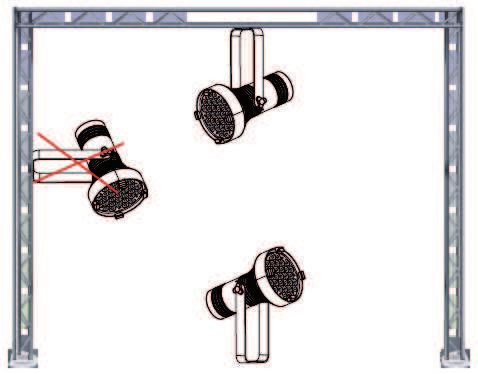
Manual | EXPO
Features
 •    Light Source:31*10W CW LEDs
 •    Lens:20°
 •    Power consumption:350W
 •    Voltage:100V-240V, 50/60Hz
 •    Run Mode: DMX 512
 •    DMX Channels: 1 & 2
 •    Built-in Effect: strobe
 •    TFT display with four buttons
 •    Material: Aluminum body
 •    IP20
 •    Temperature: -30‘C-45‘C
 •    Dimension: 234×494.5 mm
 •    N.W. : 8.0 KG
 •    G.W. : 10.0 KG

Mounting
When installing the unit, the trussing or area of installation must be able to hold 10 times the weight without
any deformation. When installing the unit must be secured with a secondary safety attachment, e.g. and appro-
priate safety cable. Never stand directly below the unit when mounting, removing, or servicing the unit.
Overhead mounting requires extensive experience, including calculating working load limits, installation mate-
rial being used, and perodic safety inspection of all installation material and unit. If you lack these qualifcations,
do not attempt the installation yourself. The installaiton should be checked by a skilled person once a year.

The EXPO is fully operational in
two different mounting positions, hanging
upside-down from a ceiling or set on a flat
level surface. To avoid internal damage to
the unit, never mount the unit on its side as
illustrated above. Be sure this fxture is kept
at least 0.5m away from any flammable
materials (decoration etc.). And you’d better
use and install the supplied safety cable as
a safety measure to prevent accidental da-
mage and/or injury in the event the clamp
fails (see next page).
Manual | EXPO
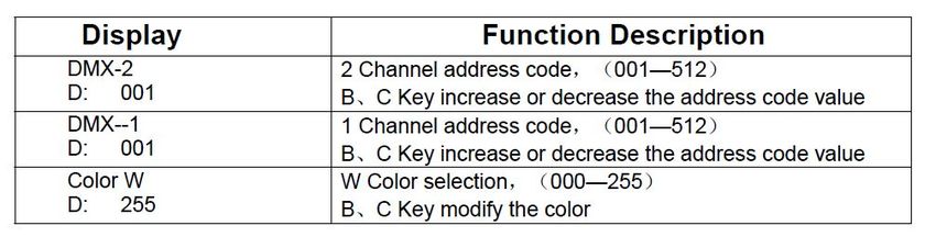
DMX control mode
DMX 1 channel
channel value function
1 0 - 255 Adjust CW All LED dimmer
DMX 2 channel
channel value function
1 0 - 255 Adjust CW All LED dimmer
0-8 NO function
2
9 - 255 Strobe(from slow to fast)
DMX 5 channel
channel value function
1 0 - 255 Adjust CW All LED dimmer
0-8 NO function
2
9 - 255 Strobe(from slow to fast)
0-9 Default
10 - 50 Auto 1
51 - 100 Auto 2
101 - 150 Auto 3
3
151 - 200 Auto 4
200 - 255 Auto 5
0 -255 Auto mode speeds
0 -255 Id address set
4 0 - 255 Auto mode speeds
5 0 - 255 Id address setManual | EXPO
10. CABLE CONNECTORS
Cabling must have a male XLR connector on one end and a female XLR connector on the other end.
DMX connector configuration
Caution: Do not allow contact between the ground and the fixture’s chassis ground. Grounding the ground can
cause a ground loop, and your fixture may perform erratically. Test cables with an ohm meter to verify positive
pole and to make sure the pins are not grounded or shorted to the shield or each other.
3-PIN TO 5-PIN CONVERSION CHART
Note!
If you use a controller with a 5 pin DMX output connector, you need to use a 5 pin to 3 pin adapter. The chart below
details a proper cable conversion:
3-PIN TO 5-PIN CONVERSION CHART
Conductor 3 Pin Female (output) 5 Pin Male (Input)
Ground/Shield Pin 1 Pin 1
Data ( - ) signal Pin 2 Pin 2
Data ( + ) signal Pin 3 Pin 3
Do not use Do not use
Do not use Do not useManual | EXPO Change LED board 1. Remove the nine screws on the light panel with a screwdriver. 2. Take down the whole light panel. 3. And then install the whole light panel of 20 degree. Photometric Data
Manual | EXPO

Das Lichttechnikhaus Vertriebs GmbH
Rudolf-Diesel-Str. 3, D-89312 Günzburg
Telefon     +49 (0) 82 21 207 98-0
Fax         +49 (0) 82 21 207 98-69
E-Mail      info@lth-gmbh.de
Web         www.lth-gmbh.de
You can also read