Strong Coupling, Hyperbolic Metamaterials and Optical Tamm States in Layered Dielectric-Plasmonic Media
←
→
Page content transcription
If your browser does not render page correctly, please read the page content below
ORIGINAL RESEARCH
                                                                                                                                     published: 07 April 2021
                                                                                                                            doi: 10.3389/fnano.2021.638442

                                            Strong Coupling, Hyperbolic
                                            Metamaterials and Optical Tamm
                                            States in Layered
                                            Dielectric-Plasmonic Media
                                            Manuel Rodrigues Gonçalves*

                                            Institute of Experimental Physics, Ulm University, Ulm, Germany

                                            Thin films of noble metals with thickness smaller than the wavelength of light constitute
                                            one of the most investigated structures in plasmonics. The fact that surface plasmon
                                            modes can be excited in these films by different ways and the simplicity of fabrication
                                            offer ideal conditions for applications in nanophotonics. The generation of optical modes
                                            in coupled Fabry-Pérot planar cavities and their migration to hyperbolic metamaterials is
                                            investigated. Coupled Fabry-Pérot cavities behave as simple coupled resonators. When
                            Edited by:      the intra-cavity media have different refractive indices in two or more coupled cavities
                    David Babonneau,        resonance anti-crossings arise. The application of this kind of strong coupling in sensing
     UPR3346 Institut P’ Recherche et
    Ingnierie en Matriaux, Mcanique et
                                            is foreseen. Beyond the cavity modes excited by propagating waves, also long range
           Energtique (Pprime), France      plasmonic guided modes can be excited using emitters or evanescent waves. A periodic
                       Reviewed by:         structure made by multiple plasmonic films and dielectrica supports bulk plasmons, of
                         Keke Chang,        large propagation constant and increasing field amplitude. The optical response of these
          Ningbo Institute of Materials
           Technology & Engineering,        structures approaches that of the hyperbolic metamaterial predicted by the effective
                           CAS, China       medium theory. Light can propagate with full transmission in a structure made of a
                             Hao Tian,
             University of Technology
                                            photonic crystal based on quarter wavelength layers and a second photonic crystal with
                    Sydney, Australia       an overlapping forbidden band, but presenting a non-trivial topological phase achieved
                *Correspondence:            by band inversion. This is due to excitation of optical Tamm states at the boundary
        Manuel Rodrigues Gonçalves          between both crystals. The extension to multiple optical Tamm states using dielectric
       manuel.goncalves@uni-ulm.de
                                            and plasmonic materials and the symmetries of the edge states is investigated.
                   Specialty section:       Keywords: surface plasmon, strong coupling, hyperbolic metamaterial, optical Tamm state, topological insulator
         This article was submitted to
                       Nanomaterials,
               a section of the journal
         Frontiers in Nanotechnology
                                            1. INTRODUCTION
       Received: 06 December 2020           Since the discovery of surface plasmons in thin metal films excited by electron beams, by Ritchie
          Accepted: 08 March 2021
                                            (1957), the investigation of plasmonic resonances on layered structures based on noble metals and
           Published: 07 April 2021
                                            their applications has a steady increase of attention by the scientific community. This is largely
                            Citation:       due the geometrical simplicity of the one-dimensional structures and the properties of the near-
         Gonçalves MR (2021) Strong
                                            fields generated by the excitation of surface plasmon modes. Over the last decades planar layered
   Coupling, Hyperbolic Metamaterials
  and Optical Tamm States in Layered
                                            stacks of noble metal films combined with dielectrics have been used in applications as refractive
          Dielectric-Plasmonic Media.       index sensors (Homola, 2008), structures for fluorescence decay engineering (Amos and Barnes,
       Front. Nanotechnol. 3:638442.        1997; Barnes, 1998; Liebermann and Knoll, 2000), hyperbolic metamaterials (Cortes et al., 2012;
    doi: 10.3389/fnano.2021.638442          Poddubny et al., 2013; Shekhar et al., 2014; Guo et al., 2020), strong-coupling between emitters and

Frontiers in Nanotechnology | www.frontiersin.org                                  1                                    April 2021 | Volume 3 | Article 638442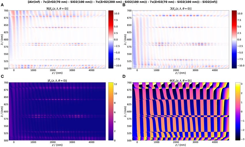
Gonçalves Strong Coupling, HMMs and OTS
plasmon modes (Bellessa et al., 2004; Törmä and Barnes, 2014; Three examples of layered structures and the application of
Chikkaraddy et al., 2016), and the one-dimensional and two- the corresponding surface plasmon modes are discussed. In first
dimensional photonic topological insulators (Su et al., 1979; place, the properties of Fabry-Pérot modes in planar cavities
Kaliteevski et al., 2007; Wang et al., 2008; Obana et al., 2019; based on silver mirrors and their application in the generation of
Henriques et al., 2020). strong coupling between cavities is discussed. These resonances
Despite the intensive research already done, the motivation are due to cavity modes and not to guided plasmonic modes, but
to study some of the optical properties of layered media and both can coexist. These structures offer a significant advantage
the wide range of applications of the plasmon resonances did in sensing over the classical plasmonic resonators because they
not fade. Layered dielectric media play a very important role in provide optical resonances with a quality factor or the order of
optics, as in lasers, optical filters, and in non-linear optics. The Q ∼ 100 and simultaneously, the silver surface can be isolated
insertion of plasmonic films into dielectric layered media not from an analyte.
only adds mathematical complexity and increases the degrees When several identical Fabry-Pérot resonators are stacked
of freedom for optical manipulation, but allows to confine and together and the layer dimensions become much smaller than
propagate optical fields to a level never achieved by photonic the wavelength another effect arises. Fabry-Pérot resonances
media. This degree of optical confinement is at the base of the cease to exist, but a new family of guided plasmon modes
modern applications of classical and quantum physics. arises: bulk plasmons with large k-vectors. These modes are
In this article several less investigated properties of surface representative of the hyperbolic dispersion arising for an infinite
plasmon modes in layered media are addressed. The main number of bilayers. To understand this uniaxial dispersion the
features of the near-fields and propagation properties are effective medium theory based on the homogenization of the
compared among different structures. Indeed, small changes in dielectric function in two orthogonal directions has been used.
the layer thickness leads to completely distinct optical regimes, However, this theory cannot be used to investigate single plasmon
but some characteristics of the optical modes are preserved. This modes and their propagation constants. Finite length plasmonic-
includes the application of planar cavity Fabry-Pérot resonators dielectric structures have a number of modes identical to the
to generate strong coupling. The analysis of coupled surface number of interfaces and their properties can be analized using
plasmon modes in finite sized metal-dielectric stacks to obtain the transfer matrix method.
hyperbolic metamaterials and optical Tamm states follows. The third class of structures is based on the optical Tamm
To my knowledge the application of Fabry-Pérot cavities to states, arising in coupled one-dimensional photonic crystals with
demonstrate classical strong coupling between light modes and a non-trivial Zak phase and between a photonic crystal and
its potential on sensing applications was not yet explored. The plasmonic film. The discussion addresses cases beyond the single
strong coupling between small plasmonic cavities (Ameling and interface.
Giessen, 2012) and beyond the light line (evanescent waves) has
been investigated (Menghrajani and Barnes, 2020). 2. THEORY AND SIMULATION METHODS
The investigation of hyperbolic metamaterials based on
periodic metal-dielectric bilayers is often based on the effective
OF PLASMONIC MODES
medium theory and on the Kronig-Penney model. In this article In this section the properties of plasmonic modes in one and two
the plasmonic modes excited in finite layered media are analyzed interfaces are summarized. The application of the transfer matrix
without approximation models. The plasmonic modes exhibit method and the scattering matrix method in multiple layers in
rich symmetry properties, not possible to investigate using the order to determine the dispersion relation is presented.
theoretical models based on infinite layered media. On the other
hand, the investigation of the optical Tamm states closely related 2.1. Surfaces Plasmons in Single Metal
to photonic topological insulators in one dimension has been
Layer
limited to a single interface. In this article the effects arising for
A p-polarized plane electromagnetic shinnes on a metal film,
double edge states are discussed.
of thickness d ≫ λ and parallel to the XY-plane, with complex
Samples were fabricated for the experimental characterization
dielectric function ǫm (ω) = ǫm,r + ǫm,i . The upper medium has
of Fabry-Pérot coupled optical cavities and the experimental
permittivity ǫ1 . The magnetic field near the interface is given by 1
demonstration of strong coupling between light modes. Samples
for experimental verification of the coupled optical Tamm states
Hy = H0 f (z) exp[i(βx − ωt)], (1)
were also fabricated and characterized.
The article is structured in the following way. A short
where β = kr + iki and electric field components are
description of the simulation methods used is given. The theory
of plasmon modes in single and double metal-dielectric interfaces
dHy
in thin films is summarized. In more complex structures made of E x = i
multiple layers, where the solutions of Maxwell’s equations hardly ωǫ dz (2)
can be found analytically, the transfer matrix method and the Ez = − k Hy
ωǫ
scattering matrix method are used to obtain the mode dispersion
and the field profiles. The fabrication techniques and the optical 1 The upper and lower media can be analyzed even more generally than dielectric
characterization is presented in the following section. and metal as in Yang et al. (1991).
Frontiers in Nanotechnology | www.frontiersin.org 2 April 2021 | Volume 3 | Article 638442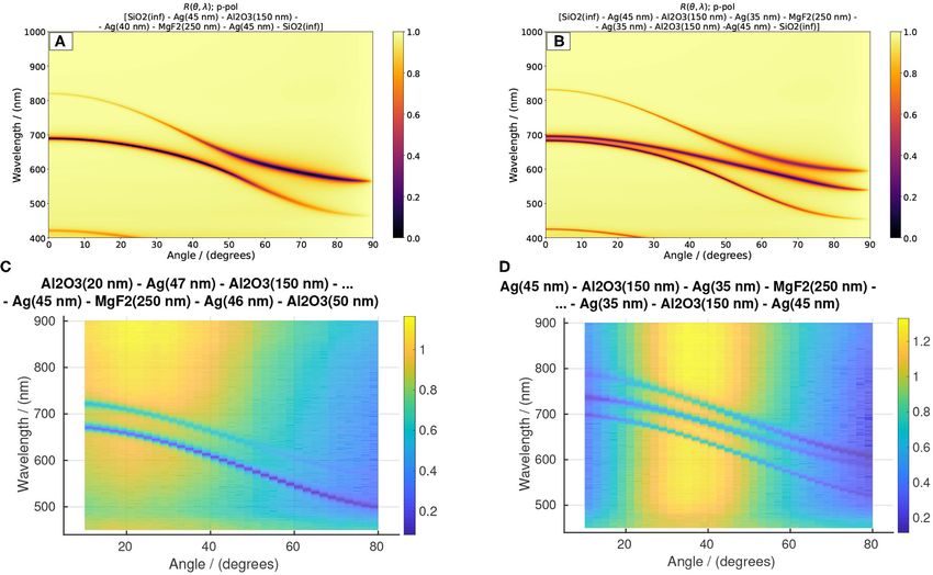
Gonçalves Strong Coupling, HMMs and OTS
The function f (z) is an exponential decaying function with form for fixed β, has larger damping due to larger ki value and is
( therefore called short range surface plasmon (SRSPP) (Sarid,
f (z) = exp(−α1 z), for z > 0 1981; Yang et al., 1991; Berini, 2009; Konopsky and Alieva, 2009).
(3) The the excitation of a single surface plasmon mode in a thin
f (z) = exp(α2 z), for z < 0
metal film is easily achieved using different dielectric media
where (asymmetrical structure dielectric-metal-dielectric, or DMD also
q q called insulator-metal-insulator, or IMI) in both sides of the
α1 = β 2 − k20 ǫ1 and α2 = β 2 − k20 ǫm (4) metal (Kretschmann and Raether, 1968; Otto, 1968; Raether,
1988). The excitation of both modes is more challenging, because
with k0 = ω/c. The dispersion relation is obtained from the the k-vector of the light is always smaller than kSPP . For that it
continuity of tangential components of the electric field is necessary to use evanescent wave excitation. The propagation
length of a surface plasmon mode is defined by Raether (1988),
ǫ1 α2 + ǫm α1 = 0 (5)
1
L= . (10)
Then the real part of β reads 2ki
ǫ1 ǫm,r
2 A large imaginary part of β is reflected in a short propagation
kr = k0 (6) length. Long propagation length is desired in applications and
ǫ1 + ǫm,r
plasmonic waveguides and long range optical interactions (Berini
This solution is real and therefore, there is a surface wave et al., 2007).
propagating at the interface metal-dielectric. However, the k-
vector of the incoming light wave k0 n1 cos θ never equals kr , 2.2. Matrix Formalisms for Layered Media
independently of the angle of incidence θ . That is, any plane The calculation of the reflectance, transmittance, absorbance,
wave cannot excite the surface plasmons at a single interface. and fields in the layered structure are based on the transfer
Simultaneously, a s-polarized wave, where the electric field matrix method (Yeh, 2005). A layered medium is made of N
oscillates in the XY-plane, never excites surface plasmon in flat optical layers, each with refractive index nj and thickness dj
layers. (i = 1, 2, . . . , N), surrounded by semi-infinite media of refractive
When the thickness of the metal film d decreases to values index n0 and ns , respectively. The layered medium is illuminated
compared to its skin depth and the film is sandwiched between with a plane electromagnetic wave of p-polarization (TM), or s-
two dielectric media of constants ǫ1 and ǫ2 , there are two metal- polarization (TE). Using the amplitudes Aj and Bj in each layer,
dielectric interfaces whose surface modes interact. In that case the associated with the forward and the backward propagation waves
dispersion relation is we can use the transfer-matrix to obtain the amplitudes of the
fields in each layer. The field (either the electric field component
ǫ2 α2 (ǫ1 α3 + ǫ3 α1 ) Ey for the s-polarization, or the Hy magnetic field component for
tanh(α2 ) = − (7) the p-polarization) in the layer j, defined by the interval between
ǫ1 ǫ3 α22 + α1 α3 ǫ22
zj and zj+1 , is described by a sum of plane waves traveling in the
q opposite direction of the z-axis. It reads
where αj = β 2 − k20 ǫj , with j = 1, 2, 3. When ǫ1 = ǫ3
the equation above has two solutions. One correspondends to ψj (x, z, t) = [Aj eikz,j (z−zj ) + Bj e−ikz,j (z−zj ) ] · ei(βx−ωt) (11)
an antisymmetric electric field distribution on both sides of the
metal film (Smith et al., 2008), and the dispersion q
with β = n2j k20 − k2z,j . The relationship between amplitudes for
two consecutive layers j and j + 1 reads
α2 d ǫ1 α2
tanh =− . (8)
2 ǫ2 α1
Aj Aj+1
= Pj D−1
j D j+1 , (12)
The other has a symmetric electric field distribution Bj Bj+1
α2 d ǫ2 α1 for j = 1, 2, . . . , N. By iterating for the full layered structure
tanh =− . (9)
2 ǫ1 α2
N
Only for p-polarized light these modes can be excited. For s- A0 Y As M11 M12 As
= Pj D−1
0
Dj Pj D−1
j
Ds = ,
polarized light there are no solutions. B0 Bs M21 M22 Bs
j=1
The imaginary part of surface wave propagation constant (13)
ki = ℑ(β) of the antisymmetric mode is munch smaller than where
that of the symmetric mode. For this reason the surface plasmon
associated with an antisymmetric oscillation of the electric field exp(iφj ) 0 ω
Pj = , φj = kz,j dj = nj cos θj ,
in both sides of the metal is called long range surface plasmon 0 exp(−iφj ) c
(LRSPP). The symmetric mode, appearing at longer wavelength (14)
Frontiers in Nanotechnology | www.frontiersin.org 3 April 2021 | Volume 3 | Article 638442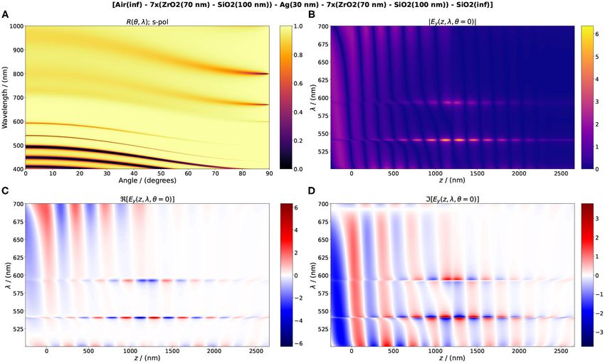
Gonçalves Strong Coupling, HMMs and OTS
and 3. SAMPLES FABRICATION AND OPTICAL
! CHARACTERIZATION
1 1
for s-polarization
n cos θ −n cos θ All samples were fabricated by successive electron-beam
j j j j
Di = ! . (15) evaporations of metal and dielectrics on glass cover slide
cos θ j cos θ j
for p-polarization substrates. The vacuum pressure before the evaporation was 10−6
n −n
j j
mbar. Samples fabricated for layered hyperbolic metamaterials
were based on coatings of Al2 O3 and silver. Aluminum oxide has
From the matrix M we can obtain the reflectance and
a major advantage over silicon dioxide when some of the layers
transmittance using
are of noble metals. It offers much better inter-layer adhesion,
2 which prevents cracking and detachment from the substrate.
M21
R = |r2 | = (16) In the fabrication of coupled Fabry-Pérot cavities and
M11 hyperbolic metamaterials layers of silver, Al2 O3 and MgF2 were
and deposited on glass substrates. For the samples based on photonic
crystals for the generation of optical Tamm states, other oxides
2
ns cos θs 1 were purchased from Kurt J. Lesker: TiO2 , ZrO2 , and Ta2 O5 .
T= , (17)
n0 cos θ0 M11 The purity of TiO2 and ZrO2 is of 99.9%. The purity of Ta2 O5
is 99.95%. The pieces for evaporation of Ag, MgF2 , Al2 O3 ,
respectively. and SiO2 purchased have higher purity, reaching 99.99%. The
An alternative way to obtain the fields in the layers and optical constants of these materials for the visible and near-
the measured quantities as the reflectance and transmittance infrared were obtained from Johnson and Christy (1972) (Ag),
is by using the scattering-matrix formalism, which has better Malitson (1962) (Al2 O3 ) and Malitson (1965) (SiO2 ), Gao et al.
numerical stability for evanescent waves (Whittaker and (2012) (Ta2 O5 ), Wood and Nassau (1982) (ZrO2 ), DeVore
Culshaw, 1999; Defrance et al., 2016; Orfanidis, 2016). The (1951) (using the Sellmeier equation of the ordinary ray for
scattering-matrix was introduced by Wheeler in the context TiO2 ), and Dodge (1984) (using the Sellmeier equation of the
of quantum physics (Wheeler, 1937), but has been also ordinary ray for MgF2 ). MgF2 in the crystalline solid form is one
applied in solid state physics (Ko and Inkson, 1988), electrical of the optical materials with the lowest refractive index (n ∼
engineering (Orfanidis, 2016), and optics (Whittaker and 1.37 in the visible), although in thin films the refractive index
Culshaw, 1999; Yuffa and Scales, 2012; Defrance et al., 2016). reaches 1.4 (de Marcos et al., 2017). It presents transparency in
The S-matrix relates the forward and backward field amplitudes a wide range of wavelengths between 150 nm and 7 µm and
in the layer l and in the layer l′ in an entirely different way. is often used in distributed Bragg reflectors and anti-reflection
The outgoing field amplitudes are determined from the incoming coatings. All the oxides have high transparency in the visible
field amplitudes by and NIR and are therefore suitable for photonic applications
were low loss is desired. The experimental band gaps of SiO2 ,
Bl S S Al
= 11 12 . (18) Al2 O3 , ZrO2 , Ta2 O5 , and TiO2 are 9, 8.8, 5.8, 4.4, and 3.5 eV,
Al′ S21 S22 Bl ′
respectively (Robertson, 2004). For wavelengths in the UV and
The elements of the M-matrix and the S-matrix in an arbitrary above 10 µm optical absorption emerges, as for Ta2 O5 (Franke
layer p are related by Li (1996) et al., 2000; Bright et al., 2013). The effective refractive index of
each coating depends on the evaporation conditions and small
−1
M11 − M12 M21 M22 −1
M12 M22
deviations from those values in the literature are expected.
S= −1 −1 (19) The samples fabricated were inspected by optical microscope.
−M21 M22 M22
For samples placed in the vertical direction to the evaporation
or equivalently source, the film thickness is in good agreement with the measured
value by the quartz balance. For some films, a comparison
S11 S−1 S−1 was made by measuring the topography of a film stripe by
M= 12 12 (20)
S21 − S22 S11 S12 S22 S−1
−1 AFM (atomic force microscopy). In substrates placed off the
12
vertical direction the film thickness decreases with increasing
In the calculations done in this article two matrix-based codes angle between evaporation source and substrate measured
were used. (a) An adapted version of the Python TMM code from the vertical. Further experimental characterization of the
based on the T-matrix calculation (Byrnes, 2019) was used for dielectric films, could be made using ellipsometry. The profile of
the reflectance, transmittance and fields in the layered structure. multilayers can be imaged by scanning electron microscopy, but
(b) An adapted version on the MATLAB Moosh code was used to was not done so far.
obtain the guided modes and field profiles of plasmonic-dielectric In order to achieve an optical wide bandgap in a planar
layered structures (Defrance et al., 2016). The fields inside the photonic crystal based on two dielectric media with a lower
structure and the reflectance and transmittance spectra of the refractive index nl and a higher refractive index nh a large
planar photonic crystals used in the generation of optical Tamm difference in the refractive index of the both materials is
states were verified using COMSOL Multiphysics. required (Yeh, 2005). Thus, a natural choice is to employ TiO2
Frontiers in Nanotechnology | www.frontiersin.org 4 April 2021 | Volume 3 | Article 638442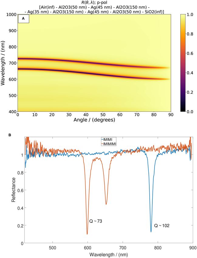
Gonçalves                                                                                                            Strong Coupling, HMMs and OTS

and MgF2 . However, the film growth conditions required for a               exceeds the light penetration depth (i.e., 200 nm for gold and
good adhesion and constant stoichiometry could not be fulfilled             silver), almost total absorption is reached at the resonances of
with the evaporation system available. The substrates could not             the single or double Fabry-Pérot resonators. The calculated and
be heated and the temperature controlled, though this is a                  experimental Q-factor of the cavity resonances can reach values
recommendation of the materials suppliers. Better films quality             above 100. Larger values can be reached in the IR, where the metal
and adhesion properties was achieved using the pair ZrO2 and                absorption of gold is low.
SiO2 . However, multiple PCs deposited in two or more steps                     The half-wavelength resonance is the first mode. Higher
lead to widespread cracking. The cracking is absent in a single             modes are excited for shorter wavelengths. The resonances at
PC up to 14 bilayers, but becomes common if the number of                   vertical incidence show very low sensitivity to changes in the
layers duplicate, or the thickness of the ZrO2 increases. The best          refractive index of the first and last media. However, for an angle
results were achieved using Ta2 O5 and SiO2 . The adhesion of               of incidence > 30 ◦ the resonances start to have large sensitivity
these films is very good, and almost no cracking was visible,               to a variation of the refractive index in the first medium.
despite to modest conditions of the evaporation. Namely, the                    When two FP cavities based on two different intra-cavity
recommended partial pressure of O2 could not be used and                    dielectric media are coupled, an anti-crossing in the dispersion of
no ion assisted deposition was employed in the electron-beam                their resonances occurs. This corresponds to a exchange of energy
evaporation process. Despite that, the reflectance experiments              between the cavities leading to a splitting in the resonance, as
show that these films can be prepared to obtain optical Tamm                in the case of identical intra-cavity medium. However, this anti-
states and verify the theoretical predictions.                              crossing can be tuned by varying the angle of incidence. This anti-
    Binary layers of Ta2 O5 and SiO2 have been used in the                  crossing of resonant modes corresponds to the classical analog
highly reflective optical coatings of the test masses of the LIGO           of the strong coupling regime between a quantum emitter and
experiment (Abbott et al., 2016; Pinard et al., 2016; Steinlechner          an optical cavity (Bellessa et al., 2004; Novotny, 2010; Ameling
et al., 2018). A advantageous property of Ta2 O5 is its low thermal         and Giessen, 2012; Törmä and Barnes, 2014; Chikkaraddy et al.,
noise and thermal stability, comparing with other oxides or                 2016).
large refractive index. The state-of-the-art of these anti-reflection           The classical analog of the strong coupling can occur not only
coatings was discussed in Granata et al. (2020). All the materials          in cavity modes excited by propagating waves, rather between
referred above were selected because of their optical properties in         surface plasmons modes, when β > k0 (Ameling and Giessen,
the visible and NIR spectral range. For longer wavelengths other            2012; Menghrajani and Barnes, 2020). The only requirement is
materials of larger refractive index and low absorption can be              the design of dispersion curves that would cross, if considered
used.                                                                       individually. The results presented is this article are however
    The reflectance of the samples was measured using a                     restricted to the case of excitation by propagating waves. The
WITec SNOM/Confocal microscope equipped with an Zeiss                       advantage of the strong coupling in coupled cavities, using two
Achrostigmat (5x, NA = 0.12) for illumination and light                     different intra-cavity dielectrics, e.g., Al2 O3 with nh ∼ 1.76 and
collection. A halogen white light source was used for excitation            MgF2 with nl ∼ 1.38 is the large sensitivity to the refractive index
and an Avantes AvaSpec-ULS-TEC spectrometer was used for                    of the first medium, for angles of incidence close to the angle
the spectral characterization. The angle-resolved reflectance of            where anti-crossing in the dispersion is reached.
the coupled Fabry-Pérot cavities presenting strong coupling were                Silver films offer the best plasmonic properties, namely long
characterized using a collimated halogen light source (Ocean                propagation length of surface plasmons, low optical absorption,
Optics HL-2000-FHSA) and an optical spectrometer (Ocean                     but are not adequate in biological sensing applications because of
Optics S2000). The samples were mounted in a rotating stage.                the chemical activity of silver. Sensing variations of the refractive
Measurements of the reflectance were done for angles between                index of a dielectric medium in the Kretschmanm-Raether setup,
10◦ and 80◦ to the vertical in steps of 2◦ .                                requires either a solution, an inert solid material, or any material
                                                                            of low chemical activity in contact with the silver, or gold
                                                                            film (Homola, 2008). Coupled Fabry-Pérot cavities presenting
4. STRONG COUPLING IN PLASMONIC                                             anti-crossing can be sandwiched by protective layers of Al2 O3
LAYERED MEDIA                                                               and be used in refractive index sensing, even for chemically active
                                                                            substances.
Layers of a metal separated by a dielectric medium of refractive                Figure 1A presents the dispersion of two coupled Fabry-Pérot
index n and thickness d ≥ λ/2 form a Fabry-Pérot (FP)                       cavities using silver films and Al2 O3 as a intra-cavity medium. In
resonator. Despite the penetration of field into the metal the              Figure 1B are presented experimental spectra obtained at normal
cavity length can be approximated to the half wavelength. In a              incidence for single and coupled cavities, indicating moderate
stack formed by 3 metal layers and two intercalated dielectric              Q-factors and narrow resonance bandwidth in the visible.
layers of the same thickness two resonances in the reflectance                  In Figure 2 are presented calculated and experimental results
and transmittance spctrum arise, with a wavelength separation               of the dispersion for two an three coupled cavities. In the
1λ dependent on the thickness of the central metal layer.                   calculated results (Figures 2A,B) the first and the last medium
Thus, a stack of two Fabry-Pérot cavities coupled by a middle               are the same. In the experimental results the illumination if from
metal layer corresponds to the optical analog of the classical              air and the substrate is glass. In the three coupled cavities there
coupled oscillators. When the thickness of last metal layer largely         are two anti-crossings. The effect of the variation of the refrative

Frontiers in Nanotechnology | www.frontiersin.org                       5                                        April 2021 | Volume 3 | Article 638442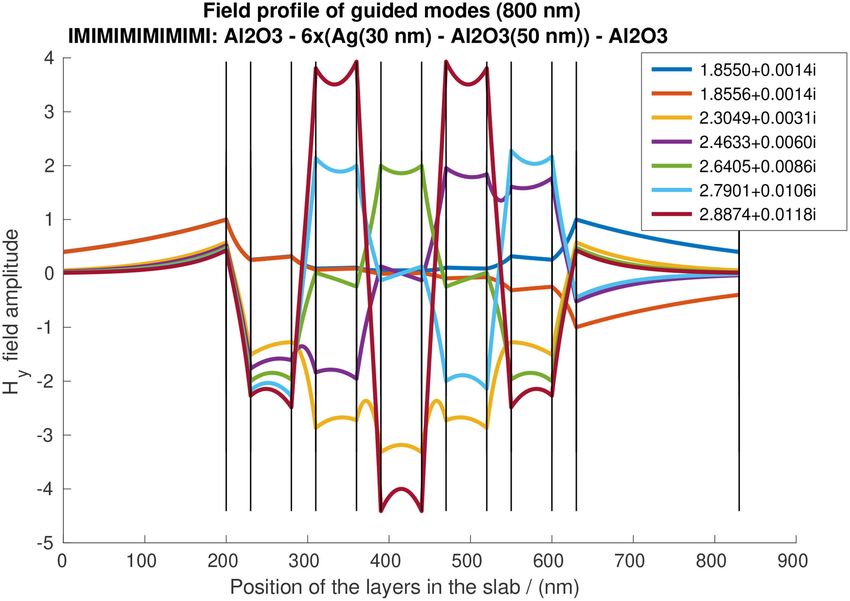
Gonçalves                                                                                                                                Strong Coupling, HMMs and OTS

 FIGURE 1 | (A) Reflectance of an IMIMIMI stack integrating two identical Fabry-Pérot cavities made of silver and aluminum oxide layers. The substrate is silicon
 dioxide and the first medium is air. (B) Experimental reflectance at normal illumination of two samples with single and double Fabry-Pérot cavities, indicating the
 respective Q-factor.

Frontiers in Nanotechnology | www.frontiersin.org                                    6                                               April 2021 | Volume 3 | Article 638442
Gonçalves                                                                                                                                   Strong Coupling, HMMs and OTS

 FIGURE 2 | Strong coupling in coupled planar Fabry-Pérot cavities. (A) Reflectance for two coupled cavities with different intra-cavity dielectric materials: aluminum
 oxide and magnesium fluoride. The strength of the coupling depends on the thickness of the inter-cavity silver layer. The tuning parameter to achieve the classical
 strong coupling is the angle on incidence of a plane wave. The dispersion also depends on refractive index of the first and the last medium. However, at vertical
 incidence the position of the resonances is almost unperturbed by changing the refractive index of the first medium. (B) Reflectance for 3 cavities. (C) Experimental
 reflectance for two cavities with p-polarized light illumination from air. (D) Experimental reflectance for three cavities in symmetric arrangement, where the middle cavity
 has the lower refractive index (MgF2 ).

index of the first medium is illustrated in Figure 3. For angles                          power loss of a dipole near a layered medium was developed by
above 30◦ the lower curve deflects rapidly with an increase of the                        several researchers in the 70’s and 80’s of the last century (Chance
refractive index n1 .                                                                     et al., 1978; Sipe, 1981; Ford and Weber, 1984) and applied in
                                                                                          problems of radiative decay engineering of fluorescent dyes near
4.1. Guided Modes in Plasmonic-Dielectric                                                 interfaces (Barnes, 1998, 1999; Novotny and Hecht, 2012).
Layered Media                                                                                The dispersion of plasmonic modes is achieved by evaluation
The cavity modes discussed in the previous section are excited by                         of the integrand functions of the power loss of a harmonic
propagating waves. Evanescent wave modes also exist for coupled                           oscillating dipole very close to a metal surface. According to the
Fabry-Pérot cavities. They propagate along any direction in the                           semi-classical theory, the decay rate of a dipole in a homogeneous
plane of the layers with constant β. For single and double metals                         medium of dielectric permittivity ǫ1 is given by γ = P/(h̄ω), with
layers forming IMI and IMIMI structures analytic and closed
form solutions of the dispersion relation of surface plasmons
                                                                                                                                    √     ω4
exist (Economou, 1969; Raether, 1988). In structures with more                                                          P = |µ|2 ǫ1           ,                          (21)
layers of dispersive materials, the roots of the complex equations                                                                        3c3
are difficult to obtain and other semi-analytical methods are more
convenient.                                                                               where µ is the dipole moment. Near an interface separating the
   The calculation of the dispersion of surface plasmon is done                           medium where the dipole is located from other semi-infinite
using two alternative methods. The first is based on the transfer                         medium, or layered media, the power loss is dependent on the
matrix method, using a point dipole source located near the first                         reflection coefficients of these media and the distance to the
dielectric-metal. The power density spectrum of the light radiated                        dipole. There is a radiating contribution and a non-radiating
by the dipole is either transmitted through the stack, absorbed by                        contribution to the decay rate, depending on the k-vector of the
the materials, or coupled into guided modes. The theory of the                            radiating field. The radiating contribution to the power spectrum

Frontiers in Nanotechnology | www.frontiersin.org                                     7                                                 April 2021 | Volume 3 | Article 638442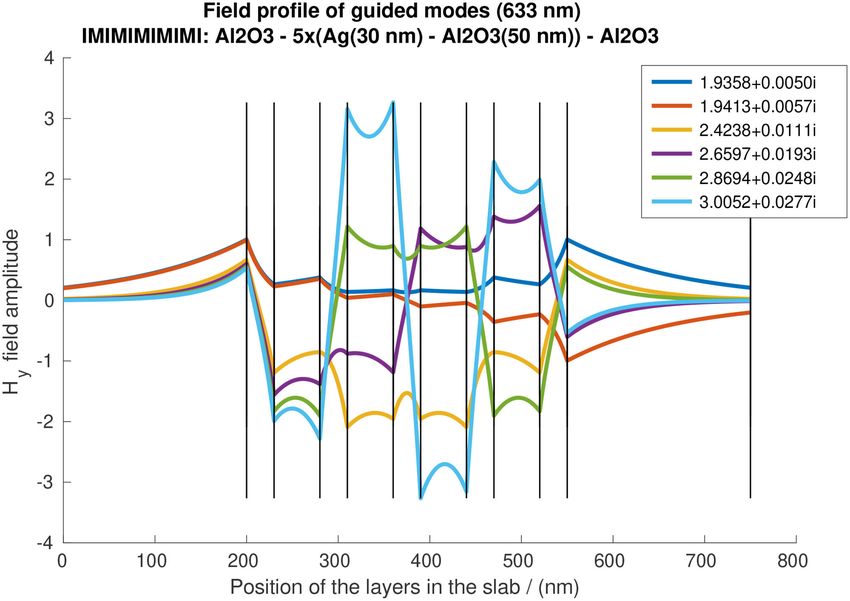
Gonçalves Strong Coupling, HMMs and OTS
FIGURE 3 | Reflectance of coupled planar cavities presenting strong coupling with dependence on the refractive index of the first medium. At vertical incidence
(θ = 0) the reflectance is independent of the refractive index of the first medium, but for angles larger then 30◦ fast deflection of the lower curve arises.
is given by layered medium) the decay rate for the parallel and perpendicular
k1
components is given by Ford and Weber (1984) and Barnes
dP
Z
Prad = dk (22) (1998)
0 dk
where k1 is the k-vector of the medium where the dipole is γk,⊥ = γ0 (1 − ηZk,⊥ ) (25)
located. The non-radiating contribution includes guided modes,
namely surface plasmon modes associated with non-propagating where
k-vectors larger than k1 . These modes can be calculated based R ∞ u3
3
P
on the Fresnel reflection coefficients from the boundary for the Z⊥ = 1 − 2 ℑR 0 du l11 + r12 exp(−2l1 d)
∞
s- and p-polarization. The quantum efficiency of the radiation is Zk = 1 − 34 ℑ 0 du lu1 1 + r12
S exp(−2l d)
1 (26)
given by the ratio 2
P
+ (1 − u ) 1 − r12 exp(−2l1 d)
γrad
η= (23) 1/2
γrad + γnr and k0 = ω/c, u = k1 /k0 and li = −i ǫj /ǫ1 − u2 with
The decay rate can be decomposed into a parallel (in-plane) j = 1, 2.
and a perpendicular (out-of-plane) term. They affect differently However, in order to obtain the dispersion relation these
the decay rate, because they rely on different contributions of integrals have not to be evaluated. If the second medium is
the Fresnel reflection coefficients for p- and s-polarization. The substituted by a layered medium of dielectric and plasmonic
density of power loss of an isotropic dipole, as it is expected from layers, the corresponding reflection coefficients are obtained
a dye molecule embedded in a dielectric transparent medium, is from the transfer matrix calculation.
given by The second method to obtain the dispersion relation relies
on the scattering matrix calculation. It is a semi-analytical
2 1
γiso = γk + γ⊥ (24) calculation method. The main advantage of the scattering matrix
3 3 comparing to the transfer matrix is its numerical stability, in
For a dipole near in a medium of dielectric permittivity ǫ1 at a particular when absorbing media are involved. The dispersion
distance d to a second medium of permittivity ǫ2 (or an arbitrary is found by solving the roots of the following equation, by the
Frontiers in Nanotechnology | www.frontiersin.org 8 April 2021 | Volume 3 | Article 638442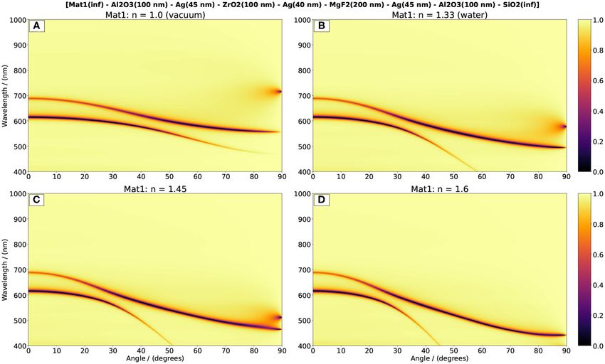
Gonçalves Strong Coupling, HMMs and OTS
steepest descent method (Defrance et al., 2016) symmetry axes of the periodic structure. For a layered medium
made of binary layers of materials with dielectric functions ǫ1 (ω)
f (β, λ) = 0 (27) and ǫ2 (ω) and thicknesses d1 and d2 , respectively, the EMT
dielectric function results into two components: one for any axis
and f is determined using the scattering matrix for the layered parallel to the layers and one for the axis perpendicular to the
structure. The MATLAB library MOOSH was employed for this layers. Assuming that the layers are parallel to XY-plane, then
purpose (Defrance et al., 2016). ǫxx = ǫyy = ǫk and ǫzz = ǫ⊥ and using k0 = ω/c the in-plane
The dispersion of the IMIMI stack calculated using the and the out-of-plane dielectric functions read
scattering matrix formalism is presented in Figure 4. The density
ǫ1 d1 + ǫ2 d2
of power loss of an isotropic dipole localized 5 nm above the first ǫ k =
silver layer is presented in Figure 5. Both dispersions relations are d1 + d2 (28)
equivalent, but the normalized k-vector is different. Hence, the ǫ⊥ = ǫ2 (d1 + d2 )
ǫ 1
differences in the values of the modes in the absissa. In Figure 4 d2 ǫ1 + d1 ǫ2
kx was normalized by the vacuum k0 , whereas in Figure 5 kx
the normalization constant is k1 = k0 n1 . The multiple plasmon The corresponding dispersion equation takes the form (Guo
modes arise as result of a hybridization between the anti- et al., 2020)
symmetric and the symmetric surface plasmon modes of a single
k2x + k2y
!
film and the cavity mode between the metal layers. They form two 2 2 2 k2z 2
(kk + kz − ǫk k0 ) + − k0 = 0. (29)
branches: the lower energy branch includes both fundamental ǫ⊥ ǫk
modes and a number of modes of larger β identical to the number
of coupled cavities. For a single Fabry-Pérot cavity is one. At The first term corresponds to the ordinary TE wave and the
higher energy levels the second branch has two modes, the anti- corresponding isofrequency surfaces (ω = const.) are spherical.
symmetric mode and a volume mode. Both branches converge The second term corresponds to the extraordinary TM waves.
to a flat dispersion for large propagation constant around 3 When ǫk > 0 and ǫ⊥ < 0 both modes exist and the second
eV (see Figure 5). The modes splitting and saturation for long term leads to a dispersion whose isofrequency have double sheet
propagation constant is a feature shared by layered hyperbolic hyperboloid shape (Type I). For ǫk < 0 and ǫ⊥ > 0 only the TM
metamaterials (Cortes et al., 2012; Shekhar and Jacob, 2014), waves can propagate and isofrequency surfaces have single sheet
discussed in the next section. The upper branch corresponds hyperboloid shape (Type II). Type II hyperboloids have negative
to a Type I hyperbolic metamaterial and the lower branch of Gaussian curvature everywhere, whereas Type I hyperboloids
modes corresponds to Type II, respectively (Cortes et al., 2012; have positive Gaussian curvature.
Shekhar and Jacob, 2014). The plasmon modes of large k-vector A hyperbolic material of Type II dispersion requires one
propagate inside the layered medium and are therefore called constituent layer allowing large anisotropy, for example a
volume plasmons. material of negative dispersion (plasmonic). By other hand, an
Samples were fabricated using bilayers of Al2 O3 and silver array of dielectric rods embedded in a distinct dielectric medium
with thickness d ≪ λ. The experimental investigation of these achieve a EMT dielectric function made of two parts: a spheroidal
samples, namely the properties of propagating plasmons and dielectric function for small k-vectors and a Type I hyperboloidal
the fluorescence lifetime of emitters near the first silver layer function for large k-vectors (Shekhar et al., 2014). However,
can provide more information for their potential application in according to the EMT a transition between Type II and type I
quantum optics experiments. can be achieved, depending on the filling factor of the plasmonic
material in the unit cell and on the wavelength range (Cortes
et al., 2012).
5. HYPERBOLIC METAMATERIALS
Array of rods of dielectric function ǫm (ω) embedded in a
A hyperbolic metamaterial is a material which has a dispersion isotropic medium of dielectric function ǫd form other example
relation described by a hyperbolic equation (Shekhar et al., 2014). of hyperbolic metamaterial, where the EMT homogenization
The isofrequency surfaces of isotropic materials have spherical can also be applied. Rods of diameter r and lattice constant L
shape. When a dielectric material is birefringent in a single arranged in a squared lattice and oriented along the z-axis have
axial direction it is called uniaxial and its dispersion equation the following EMT dielectric functions (Shekhar et al., 2014):
has isofrequency surfaces of spheroidal shape, whereas biaxial
materials have ellipsoidal isofrequency surfaces. The effective (1 + ρ)ǫm ǫd + (1 − ρ)ǫd2
ǫk =
medium theory (EMT) (Bruggeman, 1935; Rytov, 1956) is a (1 + ρ)ǫd + (1 − ρ)ǫm (30)
method of averaging the dielectric function according to the ǫ = ρǫ + (1 − ρ)ǫ .
⊥ m d
symmetry axes of the lattice. An early application of the EMT
goes back to investigation of the colors of colloidal particles in The filling factor ρ = a/A, is defined as the ratio between the
glasses (Garnett, 1904). The homogenization of the EMT requires area of the cross-section of the rods a and the area of the unit cell
a unit cell size much smaller than the wavelength of light in the of the lattice A.
frequency range considered. The resulting dielectric function is The effective dielectric function components of a hyperbolic
calculated based on geometrical parameters and on the dielectric material made of an infinite number of silver (10 nm thickness)
functions of the constituent materials and their lengths along the and Al2 O3 (20 nm) layers are presented in Figure 6. The
Frontiers in Nanotechnology | www.frontiersin.org 9 April 2021 | Volume 3 | Article 638442
Gonçalves                                                                                                                              Strong Coupling, HMMs and OTS

 FIGURE 4 | Dispersion relation of the surface plasmon modes supported in a pair of silver films separated by a layer of aluminum oxide. The semi-infinite media
 embedding the three layers is also aluminum oxide. The dielectric constants for silver were taken from Johnson and Christy (1972). The dielectric function used for the
 aluminum oxide was based on the Sellmeier dispersion equation found by Malitson (1962). The tabulated optical constant values were extracted from the online
 database https://refractiveindex.info (Polyanskiy, 2020). The dark regions correspond to the plasmon guided modes. Plasmon modes have always a k-vector
 larger then k1 = k0 n1 , the propagation constant of the first medium. The bright lines in the left region denote the cavity modes for p-polarized light.

parallel and perpendicular components were calculated using the                            The following properties can be inferred from the profiles
effective medium theory equations.                                                      of the Hy field component: (a) the first mode with a
                                                                                        symmetric profile of the magnetic field along the full structure
                                                                                        has the smallest k-vector (normalized to k0 ). It corresponds
5.1. Bulk Plasmon Modes in Finite                                                       to the antisymmetric electric field mode. (b) The second
Hyperbolic Stacks                                                                       mode with a slightly larger propagation constant has an
In order to avoid the limitations of the effective medium                               antisymmetric magnetic field distribution, considering the
theory (Kidwai et al., 2012) and the Kronig-Penney model                                symmetry plane of the full structure. (c) The volume plasmon
for infinite number of layers (Li and Khurgin, 2016) the                                modes have successive increasing values of the propagation
calculations of the field profiles in layered media of finite length                    constants and simultaneously increasing amplitudes inside the
were based on the scattering matrix method. Magnetic field                              layers. (d) The imaginary part of the propagation constant
profiles of surface modes and the bulk plasmon modes for                                ℑ[β] = ki increases with the order of the mode and
two finite stacks of dielectric and metal layers are presented                          the respective real part kr . This means that the propagation
in Figure 7 and Figure 8. Both structures have bilayers of the                          length of the bulk plasmons decreases with an increase
same thickness. The difference is the number silver films: 5                            of the propagation constant. Therefore, an arbitrary large
in Figure 7 and 6 in Figure 8. The wavelengths at which the                             number of layers and modes may be counterproductive in
profiles were calculated are in the range of the Type II hyperbolic                     applications as imaging (Li et al., 2017) and long-range
modes branch.                                                                           interactions (Biehs et al., 2016; Newman et al., 2018). Due

Frontiers in Nanotechnology | www.frontiersin.org                                  10                                              April 2021 | Volume 3 | Article 638442
Gonçalves Strong Coupling, HMMs and OTS
FIGURE 5 | Dispersion relation of the SPP modes supported in a pair of silver films separated by a dielectric layer of aluminum oxide. The materials and geometrical
parameters are the same of the Figure 4. The bright regions correspond to the highest density of power loss of an isotropic dipole located at 5 nm away the first silver
surface. The less pronounced curves for effective index kx /k0 < 1.0, correspond to TM and TE cavity modes.
to the large field strength inside some layers and the well- of quantum matter (Hasan and Kane, 2010; Haldane, 2017).
separated propagation constants of the volume modes it Topology properties are more general than geometry properties
would be of high relevance the selective excitation of single as symmetry. A topological space preserves its properties by a
plasmon modes. continuous deformation, whereas an arbitrary space deformation
often means a break of symmetry. Thus, properties of physical
systems with topological invariance are robust against small
6. PHOTONIC TOPOLOGICAL MATERIALS deformations and defects.
IN ONE-DIMENSION One of the most relevant examples of topological properties
is the Berry phase (Berry, 1984). It generalizes the concept of
The emergence of the topological order in condensed matter geometric phase introduced by Pancharatnam (1956) and it
physics has revolutionize materials science, namely in its solid is related to the parallel transport in topological spaces. The
state and optical domains. Starting with the fractional quantum close relationship of the Berry phase, arising in a cyclic path
Hall effect and the quantum spin Hall effect, where the electron of a quantum system described by a Hamiltonian under an
current is replaced by a spin current, an increasing number of adiabatic evolution, with topological properties as the Chern
effects has been discovered to posses topological properties as number and other topological invariants arising in condensed
the topological insulators (Hasan and Kane, 2010). Moreover, the matter physics was due to Simon (1983). It is remarkable that the
concepts of topological phase transition and topological insulator publication date of the article of B. Simon preceded that of the
have been also extended into photonics (Ozawa et al., 2019). article of M. Berry and coined the name of this phase. Reviews
It is also noteworthy that an early discovery of electron of phenomena in condensed matter physics manifesting Berry
states in truncated crystals, the edge states, are now investigated phase are available (Resta, 2000; Xiao et al., 2010).
from the perspective of topological insulators, giving them a Zak investigated the application to the Berry phase is solid
much large degree of generality. The impact of topological state materials characterized by a periodic lattice in real space
materials and topological insulators has achieved a large scale and by the corresponding Brillouin zone (BZ) in the momentum
attraction, from effects arising in classical waves to states space (Zak, 1989). Due to the periodicity of BZ the evolution of
Frontiers in Nanotechnology | www.frontiersin.org 11 April 2021 | Volume 3 | Article 638442Gonçalves Strong Coupling, HMMs and OTS FIGURE 6 | Dielectric functions of a plasmonic-dielectric layered medium calculated using the effective medium theory. Each bilayer is composed of silver (10 nm) and aluminum oxide (20 nm). The permittivity of silver was obtained from the optical constants from Johnson and Christy (1972). The spectral regions labeled with Type I and Type II are the regions where the real part of perpendicular and parallel parts of the dielectric function become negative, respectively. a Bloch wave along a band of the BZ is equivalent to a closed 1989; Xiao et al., 2014, 2015; Esmann et al., 2018; Wang et al., loop. Zak also found that bands of a periodic lattice, in particular 2019). Despite the fact that the edge states of photonic crystals are in one-dimension, manifest certain symmetry properties when only analogs of the edge electronic states discovered by Tamm, crossing. These properties are required for the generation of edge for historical reasons it is reasonable the call edge states arising in states (Zak, 1984, 1985). truncated photonic crystals optical Tamm states (OTS). The most well-known examples of edge states of electrons Presently many publications are dedicated to the study of in solids are the Tamm states (Tamm, 1932a,b) and Schockley edge states and the associated topological properties in two- and states (Shockley, 1939). Both are variants of the same kind of three-dimensional photonic crystals and in arrays of plasmonic edges states (Vinogradov et al., 2010). The advent of photonic particles (Wang et al., 2008, 2016; van Miert et al., 2016; Proctor crystals brought out the investigation of the optical analogues et al., 2020). In this article only one-dimensional edge states and of the edge states known for electrons in solids (Stȩślicka et al., their properties are discussed. 1990; Tikhodeev, 1991; Kavokin et al., 2005; Kaliteevski et al., 2007; Vinogradov et al., 2010) as well as in two-dimensional materials (Nakada et al., 1996; Delplace et al., 2011). Also related 6.1. Design of Single and Multiple Optical to formation of edge states in one-dimension is the model Tamm States of Su-Schrieffer-Heeger describing the excitation of solitons in Up to date most of the optical Tamm states investigated polyacetylene (Su et al., 1979) and the Peierls transition. The are based either on structures made of two planar photonic electron edges states of one-dimensional atom lattices have an crystals (Kavokin et al., 2005; Vinogradov et al., 2010; Xiao analog in photonics, substituting the periodic potential by a et al., 2014; Esmann et al., 2018), where one of them presents layered structure with periodic refractive index. band inversion, or structures based on a photonic crystal and Topological invariants of the photonic band structure in plasmonic materials (Durach and Rusina, 2012; Henriques et al., photonic crystals and in plasmonic materials coupled with 2020), or an excitonic material (Núñez-Sánchez et al., 2016). photonic crystals, as the Zak phase play an important role in Moreover, the analogy between photonic layered media and the edge state properties (Xiao et al., 2014, 2015; Gao et al., electronic lattices has been also extended to systems supporting 2015; Henriques et al., 2020). Moreover, a requirement for the mechanical waves (Xiao et al., 2015; Yang et al., 2016; Ma et al., generation of edge states in crystals is the band inversion (Zak, 2019). Frontiers in Nanotechnology | www.frontiersin.org 12 April 2021 | Volume 3 | Article 638442
Gonçalves                                                                                                                           Strong Coupling, HMMs and OTS

 FIGURE 7 | Profiles of the field component Hy for λ = 633 nm along the stack of 5 silver layers of 30 nm thickness, separated by aluminum oxide layers of 50 nm
 thickness. The first two lines correspond to the Hy with symmetric and antisymmetric profile, respectively. The two modes have maximum amplitude at the external
 boundaries. By contrary, the bulk modes have increasing amplitudes with increasing kr . The vertical black lines indicate the boundaries between layers.

    The design of edge states arising in stacks of photonic crystals                  found from the dispersion relation of the layered medium, which
relies on the definition of a bulk bandgap, in an infinite photonic                   reads (Yeh, 2005)
crystal (PC1), and by establishing a correspondence between
                                                                                                                           1 n2

the bulk and the edge state. This requires that the second                                                                          n1
                                                                                       cos(KB 3) = cos(k1 a) cos(k2 b)−           +      sin(k1 a) sin(k2 b),
photonic crystal (PC2) should have an overlapping bandgap                                                                  2 n1     n2
with the first after operating a band inversion. This excludes the                                                                                     (31)
second photonic crystal to be identical to the first. In photonic                     with k1 = (ω/c)n1 and k2 = (ω/c)n2 . The thicknesses of the
crystals with binary layers the band inversion can be achieved by                     layers are d1 = a and d2 = b and the refractive indices n1 and n2 ,
changing either the values of refractive indices of the materials of                  respectively. KB is the Bloch k-vector and 3 = a + b. A similar
the layers, or by changing their thicknesses. Using the commercial                    equation arises in the dispersion of the Kronig-Penney model of
available oxides with transparency in the visible and NIR spectral                    electrons in solids (Kronig and Penney, 1931). The same method
regions, it is more practical to change the thickness of each layer.                  was used by I. Tamm to find the edge states of electrons in a one-
Semiconductors of different materials can also be used either in                      dimensional lattice, but substituting the propagation constants k1
phononic Tamm states (Esmann et al., 2018), or in electronic                          and k2 by constants related to the periodic potential function.
Tamm states in superlattices (Steslicka, 1995). The band inversion                       Forbidden gaps in the energy occur for ℜ[KB ] = nπ/3, with
of one-dimensional photonic crystals is the same kind of band                         n = 1, 2, . . . . In the forbidden bands KB 3 = π ± ix, where x is a
transformation in two-dimensional crystals, in order to obtain                        function of the refractive indices n1 and n2 (Yeh, 2005). Bandgaps
topological insulators (Parappurath et al., 2020).                                    centered in the wavelength λ = λg arise when the following
    In a photonic crystal of indefinite length the bulk Bloch                         condition is verified
modes (bands) for illumination at vertical incidence (θ = 0) are
                                                                                          k0 n1 d1 = k0 n2 d2 = jπ/2,            with j = 1, 2, 3, . . .        (32)

Frontiers in Nanotechnology | www.frontiersin.org                                13                                             April 2021 | Volume 3 | Article 638442
Gonçalves Strong Coupling, HMMs and OTS
FIGURE 8 | Profiles of the field component Hy for λ = 800 nm along the stack of 6 silver layers of 30 nm thickness, separated by aluminum oxide layers of 50 nm
thickness. The vertical black lines indicate the boundaries between layers. The symmetry center is in the central dielectric layer.
or equivalently, for input impedance for s- and p-polarized light combining
photonic crystals and dispersive media (Konopsky, 2010). The
n1 d1 = n2 d2 = jλ/4. (33) formulas obtained permit application in quite general situations
accounting for angular dependence of the incoming wave.
The band edges are also dependent on n1 and n2 . They determine The estimation of optimal conditions of excitation on LRSPP
the width of each bandgap. By varying a and b opening or in planar layered media also benefit from this calculation
closing of bandgaps can be achieved. When two semi-infinite method (Konopsky and Alieva, 2009; Delfan et al., 2015).
photonic crystals are stacked together and truncated at the same Despite the simplicity of the impedance condition, the
inversion point of the unit cell of the lattice, with two forbidden practical design of optical Tamm states for an arbitrary forbidden
bands overlap, but the Zak phases of the respective edge bands band centered around λg is more cumbersome. In practice we
reverses an edge state arises. This permits total transmission at deal with finite crystals where the Kronig-Penney model cannot
a very narrow bandwidth inside the bandgap. The tuning of be applied. A practical way to tailor the thickness of the layers
the parameters of the gaps and the respective Zak phases was for which the edge states could be found is based on the phase
discussed in detail in Xiao et al. (2014). I should be noted that of the reflection coefficient at vertical incidence (Kavokin et al.,
the definition of the unit cell centered around an inversion point 2005; Xiao et al., 2014; Gao et al., 2015). For that we calculate the
is necessary for a well-defined value of the Zak phase (0 oi π), but total reflection coefficient of a finite binary photonic crystal using
it is not a requirement for the generation of an edge state. the transfer matrix method. The phase of the reflection coefficient
Using the treatment of optical impedance leads to the can be made dependent on a parameter δ defined in the following
conditions necessary to achieve full transmission inside the way. We set the central wavelength of the forbidden band to be
gap. This is Z1 + Z2 = 0 where Z1 and Z2 are the λg and determine the quarter wavelength thicknesses to be a0 and
input optical impedances of the first and the second semi- b0 for the higher and lower refractive index layers, respectively.
infinite crystals, respectively. Konopsky found analytic solutions
Frontiers in Nanotechnology | www.frontiersin.org 14 April 2021 | Volume 3 | Article 638442Gonçalves Strong Coupling, HMMs and OTS
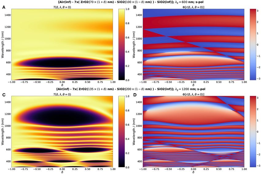
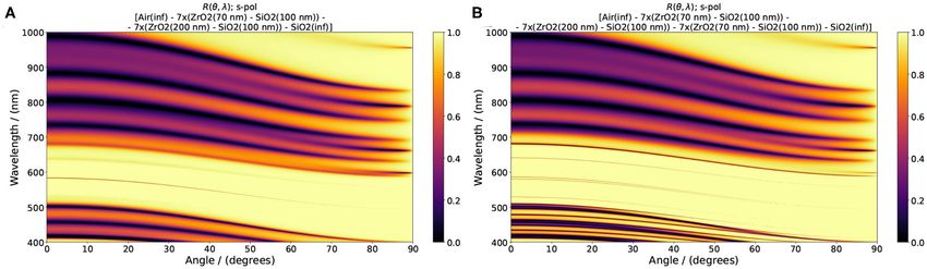
FIGURE 9 | Transmittance, (A,C), and phase of the reflection coefficient, (B,D), of photonic crystals with 7 unit cells on a silica substrate. In the upper row the
thickness of the layer with higher refractive index is a = a0 (1 + δ) nm and the layer with lower refractive index has a thickness b = b0 (1 − δ). The initial values of layers
are a0 = 70 nm and b0 = 100 nm, respectively. In the lower row the values are a0 = 135 nm and b0 = 200 nm. The choice of the initial thickness of each layer was
determined by the central wavelength and the first bandgap. λ = 600 nm in the upper row and λ = 1, 200 nm in the lower row. The parameter δ varies between –1
and 1. The tuning of optical Tamm states is achieved by combining two photonic crystals with layers thickness corresponding to overlapping bandgaps in energy and
symmetric gradients (blue and red) of the phase of the reflection coefficient at a predefined wavelength.
The reflectance and transmittance and respective reflection and bands are the dark regions in the transmittance (Figure 9). The
transmission coefficients, as the phase of the reflection coefficient corresponding phase of the reflection coefficient exhibit gradients
can be obtained for any combination of a and b such that a = either positive from 0 to π, or negative from 0 to −π. Outside the
a0 (1 + δ) and b = b0 (1 − δ), with −1 < δ < 1. Thus, the extreme forbidden bands the average phase is large and changes abruptly
pairs are a = 2a0 and b = 0, or a = 0 and b = 2b0 . from π to −π.
In Figure 9 are shown results of the transmittance and phase By stacking two or more finite crystals (see Figure 10) with
of the reflection coefficient of a photonic crystal made of SiO2 alternating sign of the phase of the reflection coefficient, edge
and ZrO2 with 7 units cells. a0 and b0 were estimated for two states arise when the impedances match. The number of solutions
central wavelengths λg = 600 nm and λg = 1, 200 nm. The unit of the impedance condition is not necessarily single valued.
cell is constituted by three layers: two lateral layers of thickness Indeed multiple edge states can be achieved. Two examples of
a/2 = λg /(nh 8) and a central layer of thickness b = λg /(nl 4) . edge states generated at the first bandgap of quarter wavelength
Therefore, the total optical length is λg /2. A unit cell built by this crystals and their counterparts with band inversion are presented
way has a mirror symmetry (inversion center) at the middle of the in Figure 11. In a stack of two photonic crystals PC1-PC2 using
layer of lower refractive index and is required for a well-defined the same materials, where the dimensions of the PC2 were
value of the Zak phase in the dispersion bands. Arbitrary values tailored in order that its second band gap has opposite sign of
of the thickness of each layer, keeping the total optical length the reflection coefficient, only ore edge state arises (Figure 11A).
constant, would not change the forbidden band for an infinite This optical Tamm state results in a narrow transmission line in
crystal but change the symmetry properties of the bands in the the middle of bandgap. The wavelength of this state at vertical
dispersion relation (Zak, 1984; Xiao et al., 2014). The forbidden illumination differs from λg = 600 nm, due to the small variation
Frontiers in Nanotechnology | www.frontiersin.org 15 April 2021 | Volume 3 | Article 638442You can also read