Update on NEET ASI Advanced Instrumentation Development Activities - Issue 12 ...
←
→
Page content transcription
If your browser does not render page correctly, please read the page content below
Issue 12 • March 2020
Update on NEET ASI Advanced Instrumentation Development Activities
Pattrick Calderoni,                                                 adoption by program stakeholders. This is true not
Idaho National Laboratory                                           only for adoption by other Department of Energy
                                                                    Office of Nuclear Energy (DOE-NE) programs, but
Instruments are the foundational                                    also for advanced reactor designers and end users
and enabling component of                                           for whom demonstrations in relevant conditions and
instrumentation and control                                         the accumulation of performance and reliability data
(I&C) systems. An instrument is                                     is a crucial step for allowing integration into the I&C
the technological application of                                    system and contributing to the plant licensing case.
measurement science principles                                      It should be noted that the conditions of a given MTR
and methods, combining sensors (or sensing elements)                irradiation experiment vary widely, depending on the
with all the necessary auxiliary components necessary
to provide a measured parameter to the I&C system.                  Continued on next page
Existing nuclear plants utilize a wide range of instruments
that provide data at varying temporal and spatial
resolutions to support operations and maintenance. In                 In this issue...
addition, instruments are a key enabling component of
demonstration tests for advanced nuclear components                   1. Program Status . . . . . . . . . . . . . . . . . . . . . . . . . . . . . . . . . . p. 1
(nuclear fuel and materials, primary loop circulation                 2. High Temperature Irradiation
pumps, heat exchangers, etc.) and advanced reactor                       Resistant Thermocouples . . . . . . . . . . . . . . . . . . . . . . . . . p. 3
concepts (e.g., microreactor core flow distribution).                 3. Evaluations of Silicon Carbide Temperature
The objective of the advanced instrumentation research                   Monitors . . . . . . . . . . . . . . . . . . . . . . . . . . . . . . . . . . . . . . . p. 5
area is to provide reliable, real-time, cost-effective,               4. Development of a versatile fiber optic
accurate, high-resolution performance measurement of                     pressure sensor for inpile applications . . . . . . . . . . . . . p. 7
existing and advanced reactor core and plant systems.
Instruments are designed, fabricated, and tested in                   5. Thermal Conductivity Needle Probe . . . . . . . . . . . . . . . p. 9
relevant and operational conditions to advance their                  6. Resonant Ultrasound Spectroscopy
technological readiness to the point that they can be                    for Inpile Micro Monitoring . . . . . . . . . . . . . . . . . . . . . .p. 11
integrated into I&C systems without the significant costs
                                                                      7. Development of an Electrochemical
and risks associated with development activities.
                                                                         Impedance Instrument . . . . . . . . . . . . . . . . . . . . . . . . . .p. 13
The development of reactor core (in-pile) instruments
                                                                      8. Inpile Instrumentation: Printed Melt Wire Chips
for material test reactor (MTR) experiments is an
                                                                         for Cheaper, Compact Instrumentation . . . . . . . . . .p. 16
important component of the program’s objective due
to the limitations of available commercial solutions                  9. Flowing Autoclave System . . . . . . . . . . . . . . . . . . . . . .p. 19
and the impact they could have on the acceleration                    10. Noninvasive HiTemp Embedded
of nuclear system component demonstrations. In                          Integrated Sensors . . . . . . . . . . . . . . . . . . . . . . . . . . . .p. 21
addition, the capability of testing developmental
instruments in MTRs is critical for demonstrating their               11. Development of an Optical Fiber Based
performance in relevant and operational conditions.                     Gamma Thermometer . . . . . . . . . . . . . . . . . . . . . . . . .p. 24
                                                         12. High Temperature Operable Harsh
The extensive deployment of advanced instrumentation       Environment Tolerant Flow . . . . . . . . . . . . . . . . . . . .p. 27
in irradiation experiments is the most effective path
to their technological maturation and consequent
         For more program information, including recent publications, please visit www.energy.gov/ne
Advanced Sensors and Instrumentation Newsletter                                                                                    2

Continued from previous page

test facility and the scope of the experiment’s duration,               through modeling and simulations. The primary path
core position, etc.; thus, they can be relevant to                      to close the technologies’ lifecycles within the NEET
demonstrations of instruments targeting either the                      ASI program is via adoption by the other DOE-NE
core or other plant systems.                                            programs. However, commercialization of novel
The implementation of research activities is organized into             instruments for component lifetime prediction
three main categories:                                                  (instruments for non-destructive examination, early
                                                                        fault detection, etc.) is also expected.
1.   The development of instruments to measure plant
     operational parameters (in- and ex-core), such as             3.   The development of testing systems to demonstrate
     neutron flux, temperature, and pressure. Instruments               instrumentation performance in relevant and
     are designed and demonstrated in MTR irradiation                   operational conditions. The primary focus is on
     experiments, but ultimately adopted by program                     irradiation experiments in MTRs, as previously
     stakeholders for integration into the I&C systems of               discussed. However, out-of-pile tests are also
     advanced nuclear plants. The primary path to close the             included when necessary to satisfy the requirements
     technologies’ lifecycles within the NEET ASI program is            for deployment in MTRs. The capability of
     through commercialization.                                         installing instruments on irradiated fuel rods and
                                                                        the development of a test rig for performance
2.   The development of measurement systems for                         demonstration of instruments in the Advanced Test
     real-time characterization of nuclear fuel and                     Reactor and High-Flux Isotope Reactor are considered
     material properties in MTR tests. These activities are             key elements in implementing the program’s mission.
     derived from analyses of existing gaps performed in
     collaboration with DOE nuclear fuel and materials             Direct-funded research and development activities
     development programs and include the measurement              implemented in FY 2020 as part of NEET ASI for the three
     of material’s properties (thermal and mechanical              categories above are listed in Table 1. Technical details for
     properties, chemistry), the characterization of its           some of the activities are included in this newsletter.
     microstructure, and the prediction of its behavior

Table 1. FY 2020 NEET ASI direct-funded projects. Highlighted in blue are projects with summaries included in this newsletter.

                                                                            • Thermocouples
                                                                            • Neutron flux sensors
                                                                            • Passive monitors
     Nuclear instrumentation to measure plant
                                                                            • Acoustic sensors
     operational parameters
                                                                            • Optical fibers
                                                                            • Wireless communication
                                                                            • Advanced manufacturing

                                                                            • Mechanical properties
                                                                            • Photo-thermal radiometry
     Measurement systems for real-time characterization
                                                                            • Probe method
     of nuclear fuel and material properties
                                                                            • Resonant Ultrasound Spectroscopy
                                                                            • Electrochemical measurements

                                                                            • Autoclave test
     Testing systems to demonstrate instrumentation
                                                                            • Fuel re-instrumentation facility
     performance in relevant and operational conditions
                                                                            • Irradiation test
Advanced Sensors and Instrumentation Newsletter                                                                             3

High-Temperature Irradiation-Resistant Thermocouples
Richard Skifton, PhD                                            associated with metallurgical phenomena, such as
Idaho National Laboratory                                       transmutation, solid state diffusion, selective evaporation,
                                                                and recrystallization. The HTIR-TC works with the
Introduction                                                    refractory metals molybdenum (+) and niobium (-) to
The High-Temperature Irradiation-                               overcome these setbacks. Both have high melting points,
Resistant Thermocouple (HTIR-TC)                                are easy to work with, and have relatively very low neutron
is generally the world’s leading                                absorption cross sections.
temperature sensor for reactor
fuel experiments and material                                   Reactor In-pile HTIR-TC Results
test reactors (Advanced Test Reactor, Massachusetts             The HTIR-TC was recently inserted into the Advanced Test
Institute of Technology Nuclear Reactor, etc.). Recently        Reactor during the Advanced Gas Reactor 5/6/7 test and
commercialized, the HTIR-TC provides real-time centerline       showed resiliency to the irradiation and high temperatures
and fuel cladding temperature measurements of reactor           experienced. See Figure 1 for temperature results of
fuel experiments during irradiations. This provides direct      HTIR-TCs compared to Type N TCs that were within close
information about fuel temperatures during Generation-IV        proximity to each other in the tests. One particular HTIR-TC
reactors, small modular reactors, and microreactor vetting      (i.e., TC5 in Figure 1) located at the geometric center of the
processes. Further, the HTIR-TC recently won the 2019           nuclear fuel (i.e., the highest temperature location) held
R&D100 award under category: Analytical/Test.                   temperatures up 1510°C consistently for approximately 9
                                                                weeks of full reactor power―that is equivalent to 12 full
The Temperature Gap                                             months. Further, the intermittent reactor shutdowns and
Between 1100°C and 1700°C, it can be difficult to find          restarts inherent in this type of experiment put the HTIR-
the right thermocouple, particularly for use in radiation       TC through severe temperature transients. Each time that
environments. Lower temperature thermocouples are at            the reactor restarted, the reading would resume as normal.
the upper end of their optimal performance in this range,       Other HTIR-TCs in the vicinity have held temperatures of
yet higher temperature thermocouples like tungsten/             1200°C–1350°C. It was noted that at higher temperatures
rhenium are at their lower operating temperature range.         the HTIR-TCs outperformed the Type N TCs .
Platinum/rhodium thermocouples that are best suited
for this temperature range experience drift and failures        Continued on next page

                   Figure 1. A small window of data for the AGR 5/6/7 results of HTIR-TCs and Type N TCs;
                   showing the HTIR-TCs outlasted and outperformed the Type N TCs in near vicinity.
Advanced Sensors and Instrumentation Newsletter                                                                                   4

Continued from previous page

Table 1 shows the comparative temperature ranges,
cost, and materials of other commercially available
thermocouples currently used in high-temperature
operations, reactor experiments, or both. The HTIR-TC bring
together the idea of high-temperature and irradiation
resistance that no other thermocouple can. In fact,
the HTIR-TC thermoelements are about 4× more “rad-
hardened” than the Type N TC.

Traditional vs. Optimized Design
                                                                 Figure 2. Traditional HTIR-TC mineral insulated metal sheathed
The HTIR-TC has been constructed using both the                  cabling versus the optimized “coaxial” cabling. The coaxial
traditional methods (i.e., mineral insulated metal sheathed      cable provides builds with longer lengths, smaller diameters,
two-wire configuration) and a new robust single wire             and more robust performance.
methodology (e.g., coaxial) using the sheath material as
the second thermoelement (see Figure 2). The latter makes        and reliably―inside a high-neutron flux environment
for a smaller diameter unit with longer length than the          at temperatures exceeding 1500°C for months on end.
traditional means, the material is also more robust and less     Further, the robust optimized design of coaxial cabling
prone to artificial junctions upon overheating.                  means the HTIR-TC can last for longer periods of time
                                                                 without any significant drift (decalibration).
Conclusion
As the name suggests, the HTIR-TC is a world record
holder in temperature measurements, specifically inside
high-temperature, irradiation environments. Sustaining
long-duration temperature readings―consistently

Table 1. Comparative table of standard thermocouples versus HITR-TC used within reactor environment.

  Thermocouple:                    Type K                   Type B                    Type N                  HTIR-TC

                                                            Platinum-
                                                                                                            Molybdenum vs.
                               Nickel Chromium            Rhodium 30%                  Nicrosil
  Materials                                                                                                    Niobium
                               vs. Nickel Alumel          vs. Platinum-                vs. Nisil
                                                                                                               (Coaxial)
                                                          Rhodium 6%
  Temperature Range             -270°C to 1260°C          0°C to 1700°C           -270°C to 1260°C            0°C to 1700°C
                                                                                                                ~$250/ft
  Cost                               ~$30/ft                   ~$250/ft                ~$50/ft
                                                                                                                ($100/ft)
  Irradiation Tolerant?                No                        No                       No                       Yes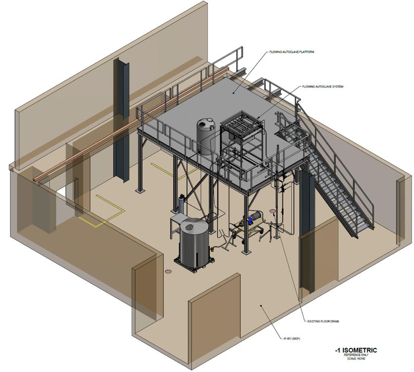
Advanced Sensors and Instrumentation Newsletter                                                                                5

Evaluations of Silicon Carbide Temperature Monitors
Malwina Wilding
Idaho National Laboratory

Introduction
The effect of irradiation on materials
properties is an important field of
study for materials usage in both
fission and fusion systems for energy
production. Neutron flux and energy
spectrums are well understood; however, the irradiation
temperature can be more difficult to determine. Since
the early 1960s, silicon carbide (SiC) has been used as a
passive post-irradiation temperature monitor because
the irradiation defects anneal out above the irradiation
temperature. [1-3] Irradiation temperature is determined by
measuring a property change after isochronal annealing or
during a continuously monitored annealing process. [1-3]
Many properties may be measured, including electrical
resistivity, bulk density, dimensions, thermal diffusivity, or
lattice spacing. Electrical resistivity is accepted as a robust
measurement technique; however, such method is time-
consuming since the steps involved must be performed in
a serial manner. [4-5] The use of thermal expansion from
continuous dilatometry is an automated process requiring
minimal setup time. [4-5] As part of a Nuclear Science User
Facilities project, low-dose silicon carbide monitors were
irradiated in the Belgian Reactor 2 (BR2) material test           Figure 1. SiC temperature monitors available for use in
reactor at Studiecentrum voor Kernenergie (SCK), Belgium.         irradiation testing include small rods and discs. Monitors
                                                                  photographed with U.S. cent for size perspective. [1]
These samples were then evaluated at the Idaho National
Laboratory High-Temperature Test Laboratory (HTTL)
to determine their peak temperature achieved during
irradiation. The technical significance of this work is that      In the second method, Idaho National Laboratory
the total dose of the irradiated monitors is significantly less   researchers developed a method aimed at using electrical
than that recommended in published literature. This paper         resistance measured during a two-pass heating-cooling
will discuss the evaluation processes available at HTTL to        cycle as a means of recovering the irradiation temperature
read peak irradiation temperature of passive monitors. [1-2]      of a SiC monitor. A fully automated means of using
                                                                  continuous measurement of resistance of SiC monitors
Methodology                                                       during heating/cooling has been developed and involves
In the first method, HTTL used resistivity measurements to        relatively inexpensive resistance measuring equipment.
find the peak irradiation temperature. The SiC monitors are       To minimize thermal perturbations, which increase
heated in the annealing furnace using isochronal                  uncertainty in the temperature measurement, a constant
temperature steps. After each isochronal annealing, the           heating rate is applied during the measurements above
specimens are placed in a resistance measurement fixture          150°C. Results indicate that the relationship between
located in the constant temperature chamber (maintained           resistance and temperature of a SiC monitor shows a
at 40°C) for a minimum of 30 minutes. An ohmic response           significant change in resistance difference slope when the
curve is generated for each monitor prior to heating. The         peak irradiation temperature is reached. [3]
peak irradiation temperature, using an electrical resistivity
technique, can be taken as the point where the resistivity        Continued on next page
begins and consistently remains, above the error band. For
this evaluation, the error band was established as the ±2σ
value based on a sample size of the first five data points
taken below 150°C. [1-2]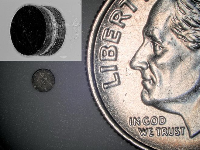
Advanced Sensors and Instrumentation Newsletter                                                                                                      6

Continued from previous page

Finally, the last method uses thermal expansion from          References
continuous dilatometry, which is an automated process
                                                              [1] Davis, K. L., et al. “Evaluation of Low Dose Silicon Carbide Temperature Monitors,”
requiring minimal setup and run time. This method uses an
                                                              IEEE Transactions on Nuclear Science, 2019, pp. 1–1, doi:10.1109/tns.2019.2957972.
optical dilatometer that requires no contact with samples,
eliminates the need for measurement calibrations and          [2] Davis, K. L., and T. C. Unruh, “Silicon Carbide Temperature Monitor Evaluation.”
corrections, and requires only one measurement run to         PLN-3473, Rev. 2, Idaho National Laboratory, February 2018.
determine irradiation temperatures. Moreover, there has       [3] Al Rashdan, A., K. Davis, T. Unruh, and J. Daw, “Silicon Carbide Temperature
been only very limited reports on the effect of irradiation   Monitor Online Evaluation,” PLN-5465, Idaho National Laboratory, September 2017.
on the thermal expansion behavior of SiC. The historical
inability to implement this process was most likely due       [4] Field, K. G., J. L. McDuffee, J. W. Geringer, C. M. Petrie, Y. Katoh, “Evaluation of
to limited resolution of the dilatometers and lack of         the Continuous Dilatometer Method of Silicon Carbide Thermometry for Passive
statistical analysis methods. This dilatometer has a very     Irradiation Temperature Determination,” Nuclear Instruments and Methods in Physics
high resolution that produces continuous measurement          Research Section B: Beam Interactions with Materials and Atoms, Vol. 445, April 15,
of length/diameter. To achieve similar anticipated error      2019, pp. 46–56.
range in determining irradiation temperature as previous      [5] Campbell, A. A., W. D. Porter, Y. Katoh, and L. L. Snead, “Method for
methods discussed, ramp rates smaller than ~2.5 K/min         Analyzing Passive Silicon Carbide Thermometry with a Continuous Dilatometer
for the dilatometry-based thermometry is recommended.         to Determine Irradiation Temperature,” Nuclear Instruments and Methods in
Limited yet significant improvement in accuracy may be        Physics Research Section B: Beam Interactions with Materials and Atoms, Vol.
achieved by further decreasing the ramp rate. [4-5]           370, March 2016, pp. 49–58.

Conclusion
SiC temperature monitors were irradiated in BR2 as part
of an Nuclear Science User Facilities project and were
evaluated at the HTTL using multiple evaluation methods
to determine their peak irradiation temperatures. The peak
irradiation temperature of each monitor was evaluated
using the resistance measurement method, an automated
resistivity method, and dilatometry-based thermometry
method. Deviations between the calculated temperature
and the evaluated temperature were within or near
published limits for all methods. A significant finding
from this evaluation is that it is possible to evaluate SiC
temperature monitors at dose levels much less than 1
dpa. SiC monitors were successfully evaluated that were
irradiated to 0.5 dpa with temperatures ranging from 240°C
to 380°C. [1-2]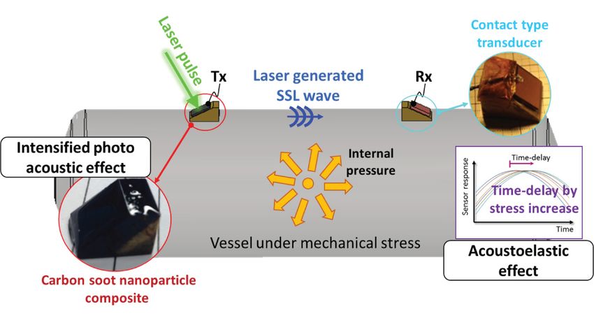
Advanced Sensors and Instrumentation Newsletter                                                                            7

Development of an Electrochemical Impedance Instrument
for In-pile Monitoring Cladding Materials Behaviors
Austin Fleming                                                   Establishing and maintaining expertise and testing
Idaho National Laboratory                                        capability is required for the qualification of each sensor.
Ashley Lambson                                                   This is especially true if the data will be used for nuclear
Idaho National Laboratory                                        fuel licensing or other safety basis measurements.
                                                                 This provides the motivation for the development
Colby Jensen                                                     of a versatile fiber-optic pressure sensor that can fit
Idaho National Laboratory                                        the needs for a variety of environments. The pressure
                                                                 sensor under development is based on Fabry-Perot
Introduction
                                                                 interferometry using a diaphragm, which deflects
Measurements from in-core                                        under external pressure, as shown in Figure 1. This
instrumentation are some of the                                  type of pressure sensor is commonly found throughout
most demanding and challenging                                   literature and some are commercially available. The
environments that exist.                                         existing developed sensors are not compatible with the
Temperatures generally range 200°C                               temperature range, sensor size, pressure range, or the
to 700°C depending on the reactor                                nuclear environment. However, there is no technical
technology. Operating pressures may                              reason for these limitations.
be ~2200 psi for pressurized water
reactors. Molten salt environments                               Sensor Design
are some of the most corrosive                                   Fiber optic sensors have many inherent benefits that
environment found in industrial                                  make them attractive for in-pile applications. These
processes. The large radiation fields                            include their small footprint, electromagnetic immunity,
further complicate the measurement                               high-temperature, high-speed sensing, and multi-modal
through inducing unwanted                                        capability. As with any classification of sensors, in-pile
electrical signals, altering material                            deployment comes with a unique set of challenges. For
properties, and limiting the available                           fiber optics, a common challenge is the radiation-induced
material for sensor construction.                                attenuation. This can be mitigated through careful sensor
Qualifying a pressure sensor that covers all requirements        design based on interference or phase measurements,
and environments that may be encountered is                      rather than magnitude-based sensing. An example of
challenging. Plenum pressure measurements are                    this experimentally measured interference spectrum is
commonly desired in the range of 2 to 10 MPa, whereas            shown in Figure 2. The cavity length, which provides a
pressure measurements in advanced reactors (helium/              measurement of pressure based on the deflection of the
sodium/molten salt) only require pressures ranging               diaphragm, is determined by the separation of adjacent
from atmospheric to 2 MPa. This large dynamic range              peaks in the interference spectrum. The longer the
of pressures generally necessitates the use of different         cavity, the closer spaced the peaks are, and vice versa if
pressure sensors for each scenario. This combined
                                                                 Continued on next page
with the material compatibility, time response, and
temperature constraints establishes the need for
qualifying a suite of pressure sensors.

               Figure 1. Diagram of a diaphragm-based extrinsic Fabry-Perot pressure sensor.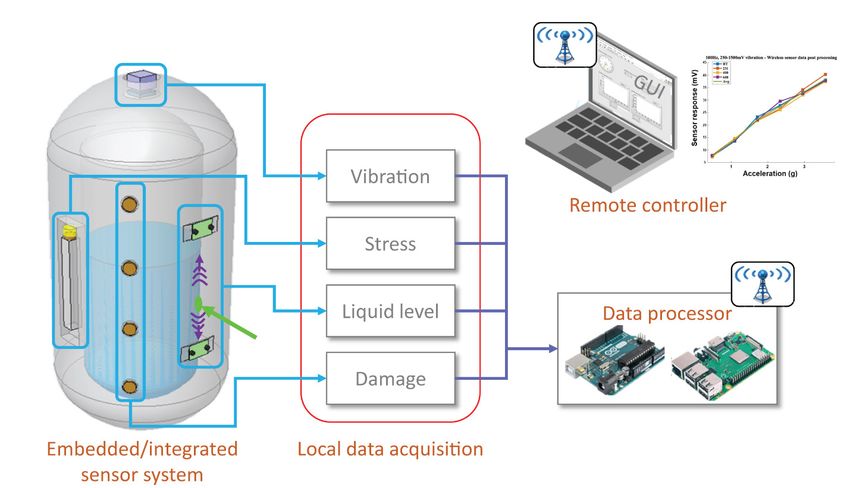
Advanced Sensors and Instrumentation Newsletter                                                                             8

Continued from previous page

                                                                 if enough light is transmitted that adjacent peaks can be
                                                                 identified, then the measurement can be conducted without
                                                                 a reduction in accuracy due to the attenuation.
                                                                 This pressure sensor design can easily be modified for
                                                                 different pressure ranges through modification of the
                                                                 diaphragm geometry or material selection. By design, it
                                                                 is capable of pressure measurements in the kHz range
                                                                 for frequency response. The first iteration of the design is
                                                                 constructed from stainless steel that enhances its corrosion
                                                                 resistance and compatibility with most environments. The
                                                                 prototype, shown in Figure 3, can operate up to 350°C
                                                                 but planned improvements should extend continuous
                                                                 operation range to ~700°C.
                                                                 Summary
                                                                 This versatile pressure sensor under development and
                                                                 testing at Idaho National Laboratory can be customized for
Figure 2. Measured interference spectrum from extrinsic Fabry
                                                                 unique applications and is compatible with several near-
Perot cavity.
                                                                 term in-pile measurement requirements. This sensor has
                                                                 the potential to support the pressure measurement needs
the cavity decreases in length. As the signal decreases due      for a wide variety of advanced reactor needs and support
to radiation induced attenuation the magnitude of these          continued in-pile testing of light-water reactor technology.
peaks decrease, but their separation is unaffected. Therefore,

Figure 3. Image of prototype fiber optic pressure sensor.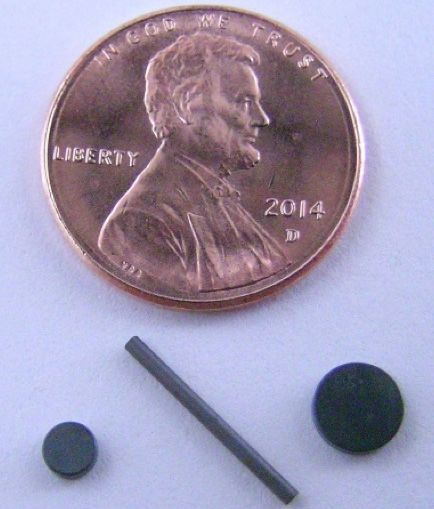
Advanced Sensors and Instrumentation Newsletter                                                                            9

Thermal Conductivity Needle Probe

Austin Fleming                                                probe is heated internally via joule heating in the heater
Idaho National Laboratory                                     wires, and the temperature response of the probe is
Kurt Davis                                                    recorded by a thermocouple. When the measurement is
Idaho National Laboratory                                     started, the probe and sample are at thermal equilibrium
                                                              and a constant power is supplied to the heater wires
Colby Jensen                                                  causing a rise in temperature. At short-time scales after
Idaho National Laboratory                                     the heater is turned on, the thermal response of the
                                                              system is dominated by the thermal properties and
Introduction                                                  geometry of the probe. As time goes on, the thermal
Thermal properties of nuclear                                 properties of the sample begin to dominate the thermal
materials significantly impact the                            response.
performance and safety analysis and                            The traditional transient line source technique
operation of nuclear reactors. One                            measures the probe temperature during this heat-up
of the most important properties is                           phase. When the temperature is plotted against the
the thermal conductivity of UO2 fuel                          logarithm of time, there is a linear region (constant
because it directly relates to how                            slope) where this slope is proportional to the thermal
much heat can be extracted from the                           conductivity of the sample. This linear region occurs on
fuel. The thermal conductivity of UO2                         long-time scales where the probe can is considered to
is a complex function of burnup that                          be a “line source” of heat. For this to be true, a significant
can result in a significant degradation                       amount of time is required, and the sample size must be
in the thermal conductivity of the                            sufficiently large that the heat does not reach the outer
lifetime of the fuel.                                         boundary condition of the sample. Otherwise, the linear
A variety of measurement techniques                           region will not be established. Using this traditional
have been used to estimate thermal                            method significantly limits the samples that can be
conductivity. These techniques include both                   measured.
measurements in post-irradiation examination and
                                                              Continued on next page
in-pile experiments. The experiments conducted in
post-irradiation examination have generally used
standard techniques, such as laser flash on a variety of
samples, to capture the burnup dependence of thermal
conductivity. [1] The Halden Reactor Project has used
centerline thermocouples in the fuel to estimate the
thermal conductivity. For this measurement, accurate
knowledge of energy generated in the fuel rodlet, and
the thermal hydraulic conditions must be known and
well characterized. Uncertainty in gap conductance
also presents challenges to this technique because of
changing conditions from fuel swelling/gap closure.
The motivation for this work is to establish the capability
to measure thermal conductivity in-pile without relying
on detailed knowledge of the thermal hydraulic boundary
conditions, heat generation, and gap conductance.

Sensor Design
Previously the approach taken for the thermal
conductivity needle probe is based on the ASTM transient
                                                              Figure 1. Cross section of the sample and needle probe geometry.
line source method. [2,3] A cross section of the sample
and needle probe geometry can be seen in Figure 1. The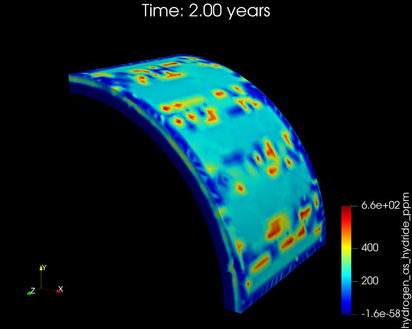
Advanced Sensors and Instrumentation Newsletter                                                                                             10

Continued from previous page

The development work at Idaho National Laboratory         References
and Boise State University has established an analytic
                                                          [1] Ronchi, C., M. Sheindlin, D. Staicu, and M. Kinoshita, "Effect of burn-up on the
model based on a thermal quadrupoles approach to          thermal conductivity of uranium dioxide up to 100.000 MWdt−1," Journal of Nuclear
account for finite sample sizes, and a thermal contact    Materials, Vol. 327, No. 1, pp. 58–76, 2004, doi: 10.1016/j.jnucmat.2004.01.018.
resistance between the probe and sample. Through
our collaboration, we compared this analytic model to     [2] ASTM, "Standard test method for thermal conductivity of plastics by means of
detailed finite element analysis with excellent           a transient line-source technique," 2001 Annual book of ASTM standards, Vol. 8, pp.
                                                          699–703, 2001.
agreement. The method was then experimentally
demonstrated using stainless steel and                    [3] ASTM, "Standard test method for determination of thermal conductivity of soil
polytetrafluoroethylene (PTFE) samples of different       and soft rock by thermal needle probe procedure," ASTM Data Ser. Publ., Vol. 5334,
radii and extracting thermal conductivity and contact     pp. 1–8, 2008.
resistance. The set of stainless steel samples were       [4] Hollar, C., A. Fleming, K. Davis, R. Budwig, C. Jensen, and D. Estrada, "A
measured with and without thermal grease to               parametric study for in-pile use of the thermal conductivity needle probe using a
demonstrate the method's resilience to changes in         transient, multilayered analytical model," International Journal of Thermal Sciences,
contact resistance. More detailed results on these        Vol. 145, p. 106028, 2019, doi: 10.1016/j.ijthermalsci.2019.106028.
findings can be found in published work in the
International Journal of Thermal Sciences. [4]

Acknowledgements
We would like to thank Boise State University for their
previous and on-going contributions to this work.
Special thanks to Courtney Hollar, Katelyn Wada, and
David Estrada.

                                                                                          Figure 2. Diagram of the cross
                                                                                          section of the experimental
                                                                                          configuration showing the needle
                                                                                          probe internals at the center.
Advanced Sensors and Instrumentation Newsletter 11
Resonant Ultrasound Spectroscopy for In-Pile Microstructure Monitoring
Robert Schley Changes in microstructure can have a pronounced
Idaho National Laboratory influence on elastic properties. Examples include grain
David Hurley restructuring, gas bubble formation, and void swelling.
Idaho National Laboratory The changing elastic properties can be measured by
monitoring the resonant frequency, which depends only
In pile monitoring of microstructure on the beam geometry, density, and the elastic properties.
evolution of nuclear fuels and Free free beams are generally specified for these types of
materials will enable an enhanced measurements as the influence of the environment can be
understanding of the effects of minimized; however, cantilever beams offer advantages for
radiation on material performance. in-reactor measurements because the beams can be held
It would also enable monitoring in rigidly in position and alignment with the detection system
pile material properties that cannot can be maintained.
be captured in a post-irradiation
environment. This has motivated the Excitation and detection of the beam vibrations are
development of facilities that combine accomplished using optical techniques. An amplitude
ion beam irradiation with transmission modulated laser serves as the excitation source and an
electron microscopy. However, optical knife edge technique using broadband white light
creating neutron beams that have a flux and energy is used for detection. Optical fibers are used to transmit
distribution representative of in pile conditions is currently the excitation and detection light to and from the sample
not possible; thus, a comparable capability to examine the eliminating the need for sensors or detectors in the
influence of neutron irradiation on microstructure evolution reactor environment.
does not currently exist. To close this capability gap will
require development of innovative instruments that can
Accomplishments
indirectly measure changes in microstructure. The work An irradiation instrument capsule for use with a
presented here describes the development of an in pile laser cantilever beam, as shown in Figure 1, was developed
resonant ultrasound spectroscopy instrument to measure and tested during the 2019 fiscal year. Thermally
changes in elastic properties that can be tied directly to driven grain restructuring (recrystallization) of a highly
changes in microstructure. textured copper sample under irradiation was studied.
Several beams for testing were cut from a rolled copper
Methodology sample using electrical discharge machining. Using the
Our approach for in-pile monitoring of microstructure instrument capsule, laboratory tests were run at 150,
consists of tracking the change in resonant frequency of a Continued on next page
vibrating beam fabricated from the material of interest. [1]
Figure 1. Section view of the test capsule showing the cantilever Figure 2. Resonant frequency before and after grain restructuring.
beam with excitation and detection probes (left), capsule prior to
reactor test (right).Advanced Sensors and Instrumentation Newsletter
12
Continued from previous page
160, 170, and 230°C to determine the time required for the
recrystallization process at each temperature. An While a cantilever beam offers the advantage of a rigidly
irradiation test was then conducted at the Idaho National held beam and large displacements, the cantilever
Laboratory’s Transient Reactor Test (TREAT) facility. The boundary condition can be extremely difficult to realize
reactor was run in steady state mode at 80 kW. After and correction factors are required to approximate the
reactor startup, the experiment was heated to 160°C and elastic constants. In addition, future studies that consider
held at that temperature for 4 hours while continuously using acoustic attenuation to characterize microstructure
monitoring the resonant frequency of the vibrating will be severely impacted by acoustic coupling to the
sample. During the grain restructuring process, the environment through the cantilever end. Designs for an
resonant frequency of the beam transitioned from 1,188 instrument capsule that allow vibration of a free beam
Hz to 921 Hz, as shown in Figure 2. The resonant while minimizing translation of the beam are being
frequency transition of the beams at 160°C from the developed and evaluated. Figure 3 shows initial testing of
laboratory tests and the irradiation a free beam capsule concept. Methods of validation and
test were then compared to determine the impact of the verification of microstructure characterization based on
irradiation on the recrystallization. The results indicated advanced modelling and simulation are also part of the
little difference between the two tests. This is in current work scope.
agreement with previous scoping studies that indicated
References
that at the dose rate provided by TREAT, radiation
enhanced diffusion would not bring about a significant [1] Schley, R. S., D. H. Hurley, Z. Hua, “Optical fiber technique for in-reactor
reduction in the recrystallization temperature. [2] However, mechanical properties measurement,” AIP Conference Proceedings, Denver, Colorado,
this experiment provides an important baseline for future July 15–20, 2012, 1511, pp. 1701–1709, 2013.
studies using uranium-based fuels. [2] Schley, R. S., L. K. Aagesen, Z. Hua, Detailed Analysis of RUS Insertion Experiment
and Scoping Studies for Performing Next Experiment using an Enriched Fuel Sample,
Current Work Idaho National Laboratory, INL/EXT-19-55962, September 2019.
Current work is expanding on the success of the irradiation
test conducted last year by developing a similar
instrument capsule that uses a free-free beam.
Figure 3. Initial testing of a free beam instrument capsule concept.Advanced Sensors and Instrumentation Newsletter 13
Development of an Electrochemical Impedance Instrument
for In-pile Monitoring Cladding Materials Behaviors
Hongqiang Hu Project Objectives and Goals
Idaho National Laboratory
This project’s objective is to prove that the electrochemical
Michael F. Hurley impedance spectroscopy (EIS) technique can be applied to
Boise State University study the non-stoichiometry, microstructure change and
Hui Xiong corrosion mechanisms of cladding materials at high
Boise State University temperatures. This will eventually lead to develop an
integrated real-time sensing technology for in-pile
The ability to probe local structural/
monitoring of changes in cladding materials by coupling it
chemical changes at critical
with model simulation and material characterization. [1]
locations is a grand challenge in
This project will involve the initial development of
current nuclear power plants. The
electrochemical sensing technologies for measuring
challenge arises from the unique
spatial and time resolved changes in cladding chemistry.
combination of temperature,
Specific attention will be paid to monitoring changes in
irradiation, corrosion, and
cladding hydride formation and deformation, and
space restriction, to which the
cladding corrosion. At the end of the project, in-pile
conventional methods cannot be
testing in an irradiation environment will be designed and
applied. These harsh and complex
assessed.
environments in nuclear reactors
make research necessary to Technology Approach
correlate material performance
with evolving microstructure and This project is a collaborative effort among researchers
then develop and deploy unique based upon strong interdisciplinary scientific collaboration
instruments to characterize the including electrochemical process, material
behavior of fuels and materials characterization, and finite element (FE) modeling. EIS
during irradiation tests. The In-Pile signals are collected from experiments on cladding
Instrumentation Initiative (I2) under the Department materials, then equivalent circuit models are established,
of Energy's Office of Nuclear Energy's (NE) Advanced from which process parameters are obtained. These results
Sensors and Instrumentation program is conducting are applied for interpreting the compositional and
these kinds of research with a vision to provide real- structural evolutions of cladding materials through the
time, accurate, spatially resolved information change of impedance response (resistance and
regarding performance of fuels and materials that can capacitance) at certain frequencies.
be directly tied to microstructure. Continued on next page
Figure 1. Impedance spectra for sample Zr-4 as a function of immersion time: left for Nyquist and right for Bode plot.Advanced Sensors and Instrumentation Newsletter 14
Continued from previous page
about its structural changes. If a dense oxide is formed,
one time constant is sufficient to model the impedance
data. The frequency dispersion commonly observed could
be attributed to surface roughness of the underlying
metal and dielectric relaxation. [1,2] If the oxide is
composed of multiple layeres with different properties,
several time constants are needed to model the data. The
changes in properties are resulted from changes in the
pore structure.
Figure 2. Ramen mapping for Zr alloy: (a) Co localized mixed
intensity maps presenting tetragonal, T1 (red) and monoclinic, High-temperature, in-situ Raman provides observation of
M4 (green) peaks. (b) Waterfall of Raman spectra near the metal/ oxidation stress at the surface of the oxide. A transition
oxide interface, corresponding to the dotted line in the mixed from tetragonal to monoclinic zirconia can be seen
intensity map.
early in the oxidation experiment as demonstrated in
Figure 2, which is induced by massive shifts in stress
Advanced material characterization includes scanning as the oxide grows. [3] In addition, atom probe
electron microscopy and tomography characterization tomography (APT) has supplied evident differences in the
of delayed hydride cracking and associated mechanisms, distribution of zirconium and oxygen at the metal/oxide
as well as visualization of microstructure evolution, interface. All metal/oxide parameters are summarized
synchrotron characterization of the structure of cladding schematically in Figure 3. The percent tetragonality,
hydride, and Raman spectroscopic characterization of stress, Volta potential, and oxygen concentration are
hydrogen evolution on surface at elevated temperatures. shown for different phases of zirconia and zirconium
Characterization results are used to verify and validate EIS metal. [4]
data and models. Preliminary results of FE modeling on hydride evolution
An FE modeling framework is developing based on the and distribution showed that the hydrogen
BISON and an FE fuel performance code, and applied concentration can penetrate the cladding/coolant
the model to one selected Zircaloy-4 cladding that is surfaces and reach a depth of 0.5 mm during 1-year
designed for less hydrogen uptake in certain reactor evolution, and most of the hydrogen stays near the
conditions. The model is composed of three sections cladding/coolant surface Figure 4. [2]
of physics processes: heat conduction, mechanical
deformation, and hydride evolutions. [2] The FE code as Continued on next page
well as microscopic identification of defects and transport
carriers will be used to help interpret the experimental
EIS data.
Progress and Results
Extensive research efforts have been made and good
progress has been achieved on this project, which
resulted in several publication. Two peer-reviewed papers
are published, a review journal paper is ready for
submission, and two more manuscripts are under
preparation with good results.
Two EIS testing systems were designed: one is for air-
environment for investigating both fuel pellets and
cladding materials; another is for aqueous conditions
for cladding materials only. The impedance spectra
for a sample Zr-4 as a function of immersion time is Figure 3. Schematic summarizing the different parameters for
demonstrated in Figure 1, which provides information each zirconia and zirconium phase.Advanced Sensors and Instrumentation Newsletter 15
Continued from previous page
Plan Forward
Future work will focus on the design and testing of the EIS
sensor at pressurized water reactor-relevant conditions
in static and flowing autoclave in order to investigate the
effects of various environmental conditions (temperature
and pressure) on cladding material corrosion mechanism.
The FE model will be finalized, and EIS spectra of hydride
and its correlation with characterization features will be
analyzed.
References
[1] Hu, H., C. Efaw, M. Reynolds, M. Hurley, C. Xiong, Development of an
Electrochemical Impedance Instrument for Monitoring Corrosion Formation (Oxide
and Hydride) on Cladding Materials, Idaho National Laboratory, INL/LTD-19-53207,
2019.
[2] Hu, H., L. Ding, C. Efaw, M. Reynolds, M. Hurley, C. Xiong, M. Long. Design of
Figure 4. FE simulations of hydride evolution Impedance Based Sensors for Monitoring Corrosion Formation of Cladding Materials,
Idaho National Laboratory, INL/EXT 19 55956, 2019.
Impact and Value to Nuclear Applications [3] Efaw, C. M., J. L.Vandegrift, M. Reynolds, S. McMurdie, B. J. Jaques, H. Hu, H. Xiong,
M. F. Hurley, “Characterization of Zirconium Oxides Part I: Raman Mapping and Spectral
This electrochemical study mainly focused on Feature Analysis,” Nuclear Materials & Energy, December 2019, Vol. 21, 100707.
the impedance technique for cladding material
characterization in a high-temperature water [4] Efaw, C. M., J. L.Vandegrift, M. Reynolds, S. McMurdie, B. J. Jaques, H. Hu, H.
Xiong, M. F. Hurley, “Characterization of Zirconium Oxides Part II: New Insights on
environment. Upon successful completion, the
the Growth of Zirconia Revealed Through Complementary High-Resolution Mapping
most important contribution of this project is the
Techniques,” Accepted at Corrosion Science, January 2020.
establishment and proof of EIS technique and
demonstration of the in-situ EIS measurement of
cladding materials under the condition of pressurized
primary coolant. Impedance spectroscopy is an efficient
and nondestructive tool to characterize the electrical
response of a particulate system, and it is also very
sensitive to changes that might have an influence on
the electrical properties, which conventional techniques
would have difficulty observing. Hence, an in-situ
EIS-based sensor can provide real-time information for
in-pile monitoring of changes in cladding materials
without interrupting the reactor operation. In addition,
with the knowledge gained from this project, in parallel
with research from others, a thorough understanding of
the zirconium corrosion system can be achieved. By
further applying this knowledge to developing better
materials, an improved performance of the new alloy
would be expected.Advanced Sensors and Instrumentation Newsletter 16
In-Pile Instrumentation: Printed Melt-Wire Chips for Cheaper,
Compact Instrumentation
Kunal Mondal The Advanced Manufacturing portion of the In-Pile
Idaho National Laboratory Instrumentation program has been exploring novel
Kiyo Fujimoto technologies that would allow for the development
Idaho National Laboratory of unique sensors that are not possible through
conventional fabrication processes. The direct-write
Michael McMurtrey techniques of aerosol jet printing and plasma jet
Idaho National Laboratory printing were identified as tools with significant promise
in diversity of application to produce wide-range
Introduction sensors that are not only miniature, but also robust. For
The harsh environment within a nuclear instrumentation, these benefits are extremely
nuclear reactor introduces unique advantageous. Aerosol jet printing and plasma jet
challenges to materials such as printing are capable of creating complex 2D designs
fuels and structural components while utilizing an ever-growing list of materials, and
as they are required to withstand these benefits provide significant potential for the
intense irradiation, high-operating development of innovative in-pile instrumentation.
temperature, large stress/strain, etc. Similar to printing documents with more familiar
To develop a better understanding computer ink-jet printers where the inks contain dyes for
for the effect of this environment on paper, the inks used in aerosol jet printing and plasma jet
these components, these materials printing contain nanoparticles of metals and/or ceramics.
must undergo rigorous testing to These inks can then be used to form narrow (anywhere
evaluate their performance under from tens to hundreds of micrometers wide) and thin
reactor conditions. Of particular (typically hundreds of nanometers thick) lines in an
interest is the effect of neutrons, arrangement as designed by the researcher. For the print
which is unique to the nuclear field. to be functional, it is sintered, which then creates wires
The ability to investigate the neutron response of a and films. These wires and films, when properly arranged,
material is facilitated by materials test reactors, such act as active or passive sensors. Active sensors, such as
as the Advanced Test Reactor (ATR) at Idaho National strain gauges, send a feedback signal that reports the
Laboratory (INL). While some experiments need only to state of the sensor during the test in real-time. Passive
study the material with post-irradiation examination to sensors, such as dosimeters, send no signal, but are
complete their research objectives, others require reliable examined after the test to determine characteristics of
data collection inside the reactor during the irradiation. the prior experiment conditions. While in many cases
As a result, significant efforts towards research and active sensors are considered superior to passive sensors
development in sensors and instrumentation have in terms of quantity of data, passive sensors may often be
provided tremendous advancements in the availability preferred as they can easily be added to any experiment.
and reliability of instrumentation for irradiation tests in This ease is provided by the fact that they do not require
materials test reactors. feedthroughs and are often relatively cheap.
Continued on next page
Figure 1. Schematic illustrating the staggery for the melt wire printing and encapsulation.Advanced Sensors and Instrumentation Newsletter 17
Continued from previous page
Figure 2. 2-mm-diameter melt wire sensor chip alongside a dime. The inset shows clear view
of laser welded chip.
Simple sensors for complex problems To address this challenge of having very limited space,
novel melt wire designs were required. For this, a melt
Melt wires are a passive sensor used to determine
wire “chip” was designed with a schematic of this design
peak temperatures during an irradiation test. Metal
provided in Figure 1. A two millimeter diameter stainless
wires are created from materials having well-known
steel disk that was half a millimeter thick was milled
compositions and melting temperatures. For irradiation
to create a dimple or pocket. Melt wires were then
testing purposes they are positioned within the reactor
printed within the pocket using one of the direct ink
to characterize the environment during the test. Once
writing techniques (each melt wire may be of a different
testing has been completed, the wires undergo visual
composition to provide a range of potential melting
inspection to investigate whether the melting point
temperatures). Utilizing a laser welder, a second steel
of the melt wire material has been achieved. This
disk was then welded overtop. This created a melt wire
information allows the researcher to determine that
chip, which is shown in Figure 2. With this design, a
the maximum peak temperature was greater than the
two-fold benefit is observed as melt wires can now be
melting point of those melt wires that did melt, and lower
easily placed within an experiment having very small size
than that of those that did not melt. Traditional melt wires
requirements, and concerns towards the environment
are commonly used test reactor experiments such as ATR.
they are exposed to can be reduced, as the wires are now
[1-2] However, analysis is highly subjective, and some test
sealed within the steel.
designs simply do not have the space for traditional melt
wires. Test capsules that are only a couple millimeters in While the sealed disks protect the metal wires from
diameter while also being packed with specimens do not corrosive test environments, they expose limitations
have the space for the wire filaments that are traditionally in traditional methods used for visual inspection. To
encapsulated in quartz. Continued on next pageAdvanced Sensors and Instrumentation Newsletter 18
Continued from previous page
overcome this, X-ray computed tomography (CT) was compositions. Furthermore, encapsulation of the melt
used to inspect the melt behavior of the sealed wire. wires provides protection from potentially corrosive
To validate the melt behavior of the printed melt wires, environments, and X-ray CT allows for visualization of
initial testing was performed in a furnace with a chip the melt wires to determine the peak temperature of the
containing a printed silver wire. It was heated to 1,000°C reactor during an experiment. Initial testing has been
to ensure that the silver wire would melt and was imaged performed outside of the test reactors to validate not
using X-ray CT before and after melting, as shown in only the manufacturing procedure, but also the ability
Figure 3. The wire deformed and material appeared to to visualize the melted wires. The first insertion of a melt
have migrated after melting, which is visible with the wire chip into a test reactor is expected to occur in the fall
X-ray CT image. of 2020.
Summary and conclusions References
INL has enhanced its melt wire capabilities with the [1] Davis, K. L., D.L. Knudson, J. E. Daw, J. L.Rempe and A. J. Palmer, “Melt Wire
introduction of advanced manufacturing techniques. It Sensors Available to Determine Peak Temperatures in ATR Irradiation Testing,” 8th
has been demonstrated that utilizing these techniques International Topical Meeting on Nuclear Plant Instrumentation, Control, and Human
enable the support of irradiation testing within ATR Machine Interface Technologies (NPIC&HMIT2012), San Diego, California, July
and other test reactors having significant space 22–26, 2012.
limitations. With the use of direct-write techniques, a [2] Rempe, L., D. L. Knudson, J. E. Daw, T. C. Unruh, B. M. Chase, K. L. Davis, A.
peak temperature sensor has been fabricated that is J. Palmer, and R. S. Schley, “Advanced in-pile instrumentation for material and
two millimeters in diameter and one millimeter thick. test reactors,” in 2013 3rd International Conference on Advancements in Nuclear
A noteworthy benefit of these chips associated with Instrumentation Measurement Methods and their Applications (ANIMMA), 2013,
miniaturization of the melt wire is the ability for one pp. 1–11, DOI: 10.1109/ANIMMA.2013.6728013.
chip to contain multiple melt wires having different
Figure 3. X-ray CT scan of the melt wires (left) before heating, and (right) after heating to 1000°C inside
a furnace. The upper images show a cross section of the entire chip, and the lower images show just
the meltwire.Advanced Sensors and Instrumentation Newsletter 19
Flowing Autoclave System
Richard Skifton FAS Facility
Idaho National Laboratory
The FAS facility is located at the Idaho National
Introduction Laboratory’s Engineering Demonstration Facility. The
facility accommodations include:
Idaho National Laboratory’s out-
of-pile, flowing autoclave system • High Bay • Control Room
(FAS) provides fast turnaround • Overhead Crane • Data Acquisition Suite
testing and active monitoring of
instrumentation. The FAS is capable • Mezzanine Access • Deionized Water System
of testing at pressurized water reactor conditions • Various Loops • Chemical Composition
prior to irradiation in the Advanced Test Reactor The high-bay access doors and ceiling with accompanying
(ATR), or similar materials test reactor. Effects of high- overhead crane allows for horizontal-to-vertical insertion
temperature, high-pressure, water chemistry, and flow of prototypic test trains into the FAS loop. Figure 1 shows
induced vibrations can be tested on the following types the complete water loop with supporting mezzanine.
of sensors:
ATR Relevancy of FAS Loop
• Temperature • Thermal Conductivity
The FAS water loop can achieve temperatures and
• Fluence (neutron) • Gamma Heating
pressures above and beyond standard commercial
• Dimensional • Fission Gas pressurized water reactors. Thus, providing a 1:1
• Loop Pressure • Loop Flowrate comparison between FAS and ATR water loops, allowing
• Water Chemistry • Crud Deposition for true pre-irradiation sensor effects testing. FAS has
relevant test sections that match several irradiation
• Crack Growth Rate • and more… positions in the ATR and other material test reactors.
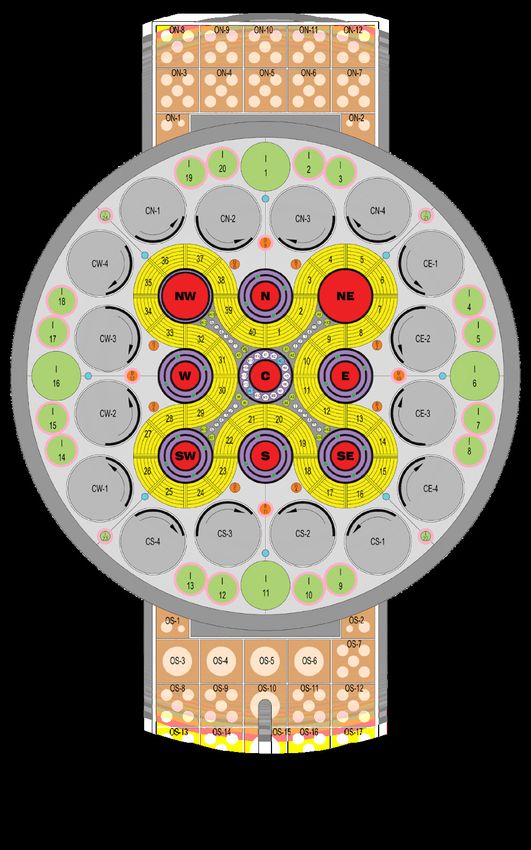
Matching FAS test sections to various irradiation
positions within the ATR are governed mainly by three
factors: cross-sectional area, desired neutron flux, and
relative availability (schedule). Three main irradiation
positions accommodate the approximate mid-range
of all three criteria: the small-I, medium-I, and large-B
positions (highlighted in red in Figure 2).
Table 1. Achievable parameters of FAS.
Parameter Measurement
Flow Rate 50 gal/min
Temperature 320°C
Pressure 2800 psi
Water Chemistry Yes, Controlled
Test Length 40 in.
Sections
Available Diameter 1 in. & 1.5 in.
Figure 1. FAS Facility
(Isometric View). For
Information Only. High bay Continued on next page
overhead crane not shown.Advanced Sensors and Instrumentation Newsletter 20
Continued from previous page
The diameter, average thermal and fast flux of these
positions are shown in Table 1.
Table 2. Achievable metrics of FAS relevant test
sections inside the ATR.
Inside
Thermal Fast Flux
Diameter
Position Flux [n/ (E>1 MeV)
(Effective)
cm2-s] [n/cm2-s]
[in]
Small-I 1.5 8.4x10¹³ 3.2x10¹²
Med-I 3.5 (1.5) 3.4x10¹³ 1.3x10¹²
Large-B 1.5 1.1x10¹⁴ 1.6x10¹³
The medium-I position, specifically the I-9 position in the
southeast corner, has an effective diameter of 1.5 in. due to
various tubing and sensor leads that need to be inserted
in order to operate. This is the main reason for FAS test
sections have an equivalent 1.5-in. inside diameter.
FAS Schedule
To discuss or schedule work in the FAS loop please contact:
Dr. Richard Skifton
208.526.2696 | Richard.Skifton@inl.gov
Figure 2. ATR core cross section with irradiation positions
relevant to the FAS highlighted in red.
CURRENT PROJECTS PLANNED TO BE TESTED IN THE FAS LOOP FOR FY 2020
March April May June July August September
Optimized design of the High-Temperature
Irradiation-Resistant Thermocouples (HTIR-TC)
Linear Variable Differential Transformer,
stressed and unstressed
• Creep Test Rig
• Constant Velocity Diameter Gauge.
Ultrasonic Thermometers (UTs)Advanced Sensors and Instrumentation Newsletter 21
Noninvasive High Temperature Embedded/Integrated Sensors (HiTEIS)
for Remote Monitoring of Nuclear Power Plants
Howuk Kim sensing mechanisms. For the last
North Carolina State University decades, there have significant
Kerrigan Sean advancements in sensor materials
North Carolina State University robustness to such environmental
conditions. For instance, non-
Bharat Balagopal ferroelectric piezoelectric single
North Carolina State University crystals, such as Lithium Niobite,
Mo-Yuen Chow Yttrium Calcium Oxoborate, and
North Carolina State University Aluminum Nitride (AlN), can
operate stably at a relatively HT
Mohamed Bourham
condition (~1,000°C) without any
North Carolina State University
phase transition. [5-6] Furthermore,
Xiaoning Jiang among existing HT single crystal
North Carolina State University materials, AlN is known for its
robust sensing performance under
Introduction radiation conditions involving
Reliable sensing is crucial to ensure neutron and gamma fluence. [7]
the safety and functionality of The goal of our research is to
nuclear power plants (NPPs). Most develop noninvasive high-
conventional NPP sensors perform temperature embedded/integrated
in an invasive manner, contacting sensors (HiTEIS) for remote
with the internal media. [1] The monitoring of NPPs Figure 1. This
typical invasive sensors are prone article presents the current research
to damage in harsh environments, status of the noninvasive HiTEIS
and most sensors have degraded reliability in the long techniques and the wireless communication system,
period of usage, which may result in frequent sensor followed by the introduction of potential future work.
maintenances and the regular shutdown of the plant. [2]
Moreover, calibration and maintenance of invasive Noninvasive HiTEIS
sensors and detectors usually expose human technicians
In this project, various noninvasive sensing methods
to radiation conditions. [3]
were investigated to measure vibration, stress, and
Noninvasive sensors enable monitoring of structural liquid level, and to detect structure damages. These
integrity and plant operation status without affecting noninvasive sensors can basically operate at the
the structure and internal media. Furthermore, outer surface of a structure as illustrated in Figure 1.
noninvasive sensing would provide a much more Piezoelectric materials were used in these sensors
economical option for sensor calibration and because of the fast response and simple structure
maintenance. Combining with the nonintrusive sensing design of piezoelectric sensors. Moreover, acoustic
technique, wireless data-transfer technologies may sensors are known with excellent wave penetration into
further reduce the possibility of human dangers and a metallic structure, and the cost effectiveness make
enhance the cost-effectiveness of plant operation since them preferable for the noninvasive sensors.
the operation status of an NPP can be monitored from a
1. Vibration sensor. The vibration sensor measures
remote and safe place. Despite many potential
a vibration level of a structure using the direct
advantages of the noninvasive sensing technique, there
piezoelectric effect, where the vibration-induced
has been a lack of non-invasive sensor investigations for
inertial force acting on the piezoelectric element
the NPP applications. One challenge might be the fact
results in an electrical charge or voltage output. For
that sensors applied in NPP structures may face harsh
the HT application, AlN piezoelectric single crystal was
environmental conditions including high temperatures
employed. In addition, platinum foils (a thickness of 1
(HT) and irradiation in NPP structures. [4] As such, it is
essential to employ proper sensing materials, as well as, Continued on next pageYou can also read