AAIB Bulletin 1/2022 - GOV.UK
←
→
Page content transcription
If your browser does not render page correctly, please read the page content below

AAIB Bulletin                         1/2022

      TO REPORT AN ACCIDENT OR INCIDENT
    PLEASE CALL OUR 24 HOUR REPORTING LINE
                 01252 512299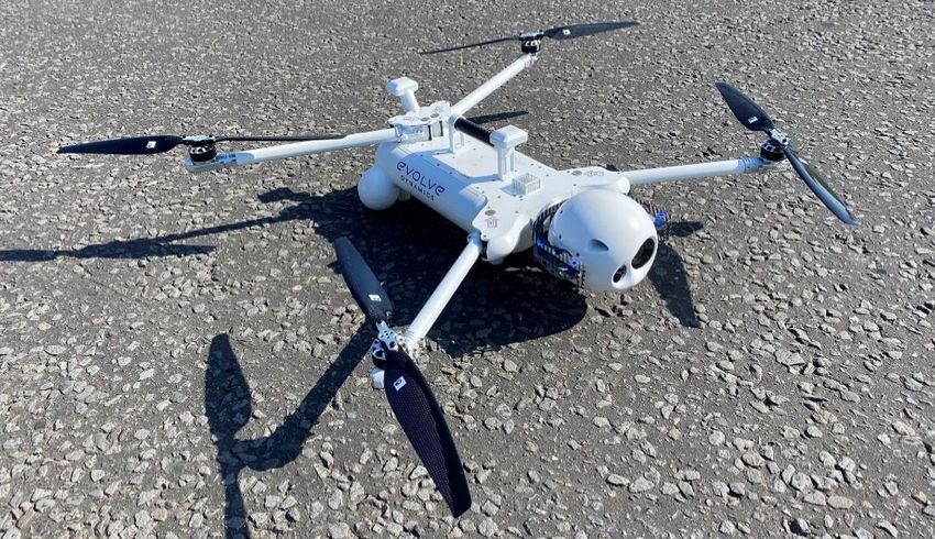
Air Accidents Investigation Branch
Farnborough House AAIB Bulletin: 1/2022
Berkshire Copse Road
Aldershot GLOSSARY OF ABBREVIATIONS
Hants GU11 2HH
aal above airfield level lb pound(s)
ACAS Airborne Collision Avoidance System LP low pressure
ACARS Automatic Communications And Reporting System LAA Light Aircraft Association
Tel: 01252 510300 LDA Landing Distance Available
ADF Automatic Direction Finding equipment
Fax: 01252 376999 AFIS(O) Aerodrome Flight Information Service (Officer) LPC Licence Proficiency Check
Press enquiries: 0207 944 3118/4292 agl above ground level m metre(s)
http://www.aaib.gov.uk AIC Aeronautical Information Circular mb millibar(s)
amsl above mean sea level MDA Minimum Descent Altitude
AOM Aerodrome Operating Minima METAR a timed aerodrome meteorological report
APU Auxiliary Power Unit min minutes
ASI airspeed indicator mm millimetre(s)
ATC(C)(O) Air Traffic Control (Centre)( Officer) mph miles per hour
ATIS Automatic Terminal Information Service MTWA Maximum Total Weight Authorised
ATPL Airline Transport Pilot’s Licence N Newtons
AAIB investigations are conducted in accordance with BMAA British Microlight Aircraft Association NR Main rotor rotation speed (rotorcraft)
BGA British Gliding Association Ng Gas generator rotation speed (rotorcraft)
Annex 13 to the ICAO Convention on International Civil Aviation, BBAC British Balloon and Airship Club N1 engine fan or LP compressor speed
EU Regulation No 996/2010 (as amended) and The Civil Aviation BHPA British Hang Gliding & Paragliding Association NDB Non-Directional radio Beacon
CAA Civil Aviation Authority nm nautical mile(s)
(Investigation of Air Accidents and Incidents) Regulations 2018. CAVOK Ceiling And Visibility OK (for VFR flight) NOTAM Notice to Airmen
CAS calibrated airspeed OAT Outside Air Temperature
cc cubic centimetres OPC Operator Proficiency Check
The sole objective of the investigation of an accident or incident under these CG Centre of Gravity PAPI Precision Approach Path Indicator
Regulations is the prevention of future accidents and incidents. It is not the cm centimetre(s) PF Pilot Flying
CPL Commercial Pilot’s Licence PIC Pilot in Command
purpose of such an investigation to apportion blame or liability. °C,F,M,T Celsius, Fahrenheit, magnetic, true PM Pilot Monitoring
CVR Cockpit Voice Recorder POH Pilot’s Operating Handbook
DFDR Digital Flight Data Recorder PPL Private Pilot’s Licence
Accordingly, it is inappropriate that AAIB reports should be used to assign fault DME Distance Measuring Equipment psi pounds per square inch
or blame or determine liability, since neither the investigation nor the reporting EAS equivalent airspeed QFE altimeter pressure setting to indicate height
EASA European Union Aviation Safety Agency above aerodrome
process has been undertaken for that purpose. ECAM Electronic Centralised Aircraft Monitoring QNH altimeter pressure setting to indicate
EGPWS Enhanced GPWS elevation amsl
EGT Exhaust Gas Temperature RA Resolution Advisory
EICAS Engine Indication and Crew Alerting System RFFS Rescue and Fire Fighting Service
EPR Engine Pressure Ratio rpm revolutions per minute
ETA Estimated Time of Arrival RTF radiotelephony
ETD Estimated Time of Departure RVR Runway Visual Range
FAA Federal Aviation Administration (USA) SAR Search and Rescue
FIR Flight Information Region SB Service Bulletin
FL Flight Level SSR Secondary Surveillance Radar
ft feet TA Traffic Advisory
AAIB Bulletins and Reports are available on the Internet ft/min feet per minute TAF Terminal Aerodrome Forecast
g acceleration due to Earth’s gravity TAS true airspeed
http://www.aaib.gov.uk TAWS Terrain Awareness and Warning System
GPS Global Positioning System
GPWS Ground Proximity Warning System TCAS Traffic Collision Avoidance System
hrs hours (clock time as in 1200 hrs) TODA Takeoff Distance Available
HP high pressure UA Unmanned Aircraft
hPa hectopascal (equivalent unit to mb) UAS Unmanned Aircraft System
IAS indicated airspeed USG US gallons
IFR Instrument Flight Rules UTC Co-ordinated Universal Time (GMT)
This bulletin contains facts which have been determined up to the time of compilation. ILS Instrument Landing System V Volt(s)
IMC Instrument Meteorological Conditions V1 Takeoff decision speed
Extracts may be published without specific permission providing that the source is duly acknowledged, the material is
IP Intermediate Pressure V2 Takeoff safety speed
reproduced accurately and it is not used in a derogatory manner or in a misleading context. IR Instrument Rating VR Rotation speed
ISA International Standard Atmosphere VREF Reference airspeed (approach)
Published 13 January 2022 Cover picture courtesy of Alan Thorne
kg kilogram(s) VNE Never Exceed airspeed
KCAS knots calibrated airspeed VASI Visual Approach Slope Indicator
© Crown copyright 2022 ISSN 0309-4278 KIAS knots indicated airspeed VFR Visual Flight Rules
KTAS knots true airspeed VHF Very High Frequency
Published by the Air Accidents Investigation Branch, Department for Transport km kilometre(s) VMC Visual Meteorological Conditions
Printed in the UK on paper containing at least 75% recycled fibre kt knot(s) VOR VHF Omnidirectional radio Range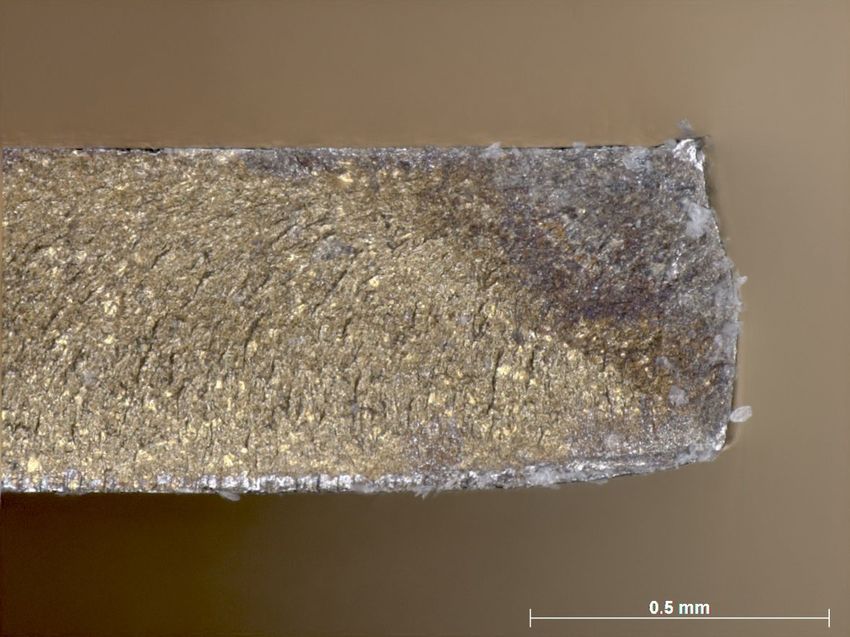
AAIB Bulletin: 1/2022

CONTENTS

SPECIAL BULLETINS / INTERIM REPORTS

         S2/2021: Boeing 737-8K5           G-FDZF   11-Sep-21             3

SUMMARIES OF AIRCRAFT ACCIDENT (‘FORMAL’) REPORTS

         None

AAIB FIELD INVESTIGATIONS

COMMERCIAL AIR TRANSPORT
FIXED WING
         None
ROTORCRAFT
         None

GENERAL AVIATION
FIXED WING
         None
ROTORCRAFT
         Airbus Helicopters AS355 F1       G-BOSN   02-Mar-21            11

SPORT AVIATION / BALLOONS
         None

UNMANNED AIRCRAFT SYSTEMS
         None

AAIB CORRESPONDENCE INVESTIGATIONS

COMMERCIAL AIR TRANSPORT
         Airbus A319-111                   G-EZBD    13-Jul-21          27
         Boeing 737-4Y0F                   EC-MIE   16-Jun-21           31

GENERAL AVIATION
         Cessna 120                        G-AJJT    15-Jul-21          36
         Europa                            G-FLOR   23-Jun-21           38
         Jabiru J400                       G-CCPV   17-Aug-21           48

SPORT AVIATION / BALLOONS
         None

© Crown copyright 2022                 i                     All times are UTC
AAIB Bulletin: 1/2022

CONTENTS Cont

AAIB CORRESPONDENCE INVESTIGATIONS Cont

UNMANNED AIRCRAFT SYSTEMS
         DJI Inspire 2              N/A                             20-Jul-21         51
         Evolve Dynamics Sky Mantis N/A                            14-Jan-21 ∫  ∫     53
         		                                                        17-Feb-21

RECORD-ONLY INVESTIGATIONS

         Record-Only UAS Investigations reviewed:   October / November 2021		         65

MISCELLANEOUS

ADDENDA and CORRECTIONS
         DH82A Tiger Moth                           G-AXBW         13-Aug-21          71

List of recent aircraft accident reports issued by the AAIB		                         73
                         (ALL TIMES IN THIS BULLETIN ARE UTC)

© Crown copyright 2022                       ii                            All times are UTC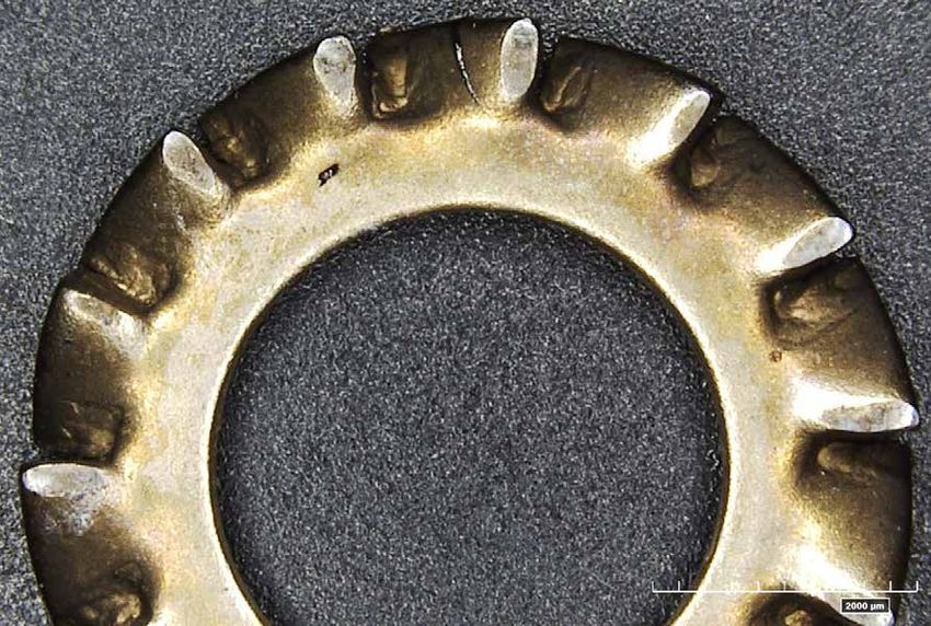
AAIB Bulletin: 1/2022

                 AAIB Special Bulletins / Interim Reports
                         AAIB Special Bulletins and Interim Reports

                         This section contains Special Bulletins and
                         Interim Reports that have been published
                            since the last AAIB monthly bulletin.

© Crown copyright 2022                       1                         All times are UTC
Farnborough House
Berkshire Copse Road
Aldershot, Hants GU11 2HH

Tel:01252 510300
Fax: 01252 376999
www.aaib.gov.uk

AAIB Bulletin S2/2021
SPECIAL
SERIOUS INCIDENT

Aircraft Type and Registration:                       Boeing 737-8K5, G-FDZF

No & Type of Engines:                                 2 CFM56-7B27/3 turbofan engines

Year of Manufacture:                                  2008 (Serial no: 35138)
Date & Time (UTC):                                    11 September 2021 at 1240 hrs

Location:                                             Aberdeen Airport

Type of Flight:                                       Commercial Air Transport (Passenger)

Persons on Board:                                     Crew - 6                    Passengers - 67

Injuries:                                             Crew - None                 Passengers - None

Nature of Damage:                                     None

Commander’s Licence:                                  Airline Transport Pilot’s Licence

Commander’s Age:                                      56 years

Commander’s Flying Experience:                        15,490 hours (of which 1,524 were on type)
                                                      Last 90 days - 67 hours
                                                      Last 28 days - 62 hours

Information Source:                                   AAIB Field Investigation

Introduction

At 1341 hrs on 13 September 2021, the AAIB was informed that a serious incident had
occurred to Boeing 737-800, registration G-FDZF, during a go-around at Aberdeen Airport on
11 September 2021. The AAIB began an investigation assisted by the operator, the National
Transportation Safety Board in the USA, and the aircraft manufacturer.

During the go-around, which was initiated at 2,250 ft amsl, the aircraft initially climbed, but just
before it reached the cleared altitude of 3,000 ft amsl it began to descend. It descended to
1,780 ft amsl (1,565 ft agl) with a peak rate of descent of 3,100 ft/min, and it accelerated to an
airspeed of 286 kt (the selected airspeed was 200 kt) before the crew corrected the flightpath.

This Special Bulletin contains facts which have been determined up to the time of issue. It is published to inform the
aviation industry and the public of the general circumstances of accidents and serious incidents and should be regarded as
tentative and subject to alteration or correction if additional evidence becomes available.
© Crown copyright 2021
                                                             3                                             All times are UTC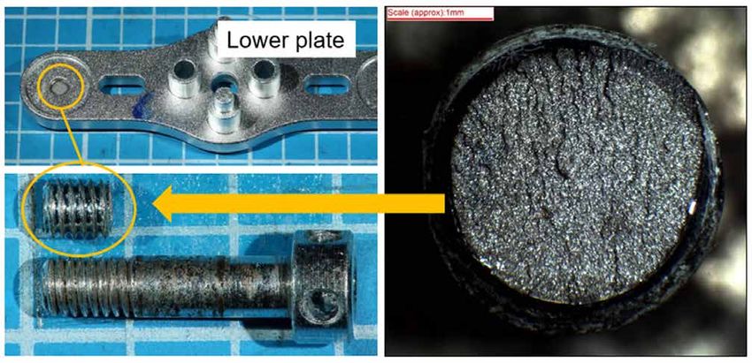
AAIB Special Bulletin: S2/2021                        G-FDZF                                           AAIB-27673

The pilots of G-FDZF, like many other pilots, had not flown for significant periods during
the 18 months before this incident. Although the investigation has not established a link
between this incident and a lack of recent line flying, it is clearly a possibility. Therefore,
this Special Bulletin is published to raise awareness of this event and to highlight that
go‑arounds from intermediate altitudes on an approach can provoke errors because they
are not practiced frequently.

History of the flight

The crew of G-FDZF had operated a passenger flight from Newcastle International Airport to
Palma de Majorca before operating the incident flight from Palma to Aberdeen Airport. The
aircraft departed Palma at 1047 hrs with 67 passengers and 6 crew on board. At 1230 hrs
the flight crew established contact with Aberdeen Radar for a radar vectored CAT I ILS
approach to Runway 34 at Aberdeen. At 1235 hrs, as the aircraft was descending through
5,100 ft amsl, the crew were informed by ATC that there was a possibility that they may
have to discontinue the approach, in which case they should expect a climb straight ahead
to 3,000 ft amsl. This was because a search and rescue helicopter, which was currently on
the ground at the airport, would take priority once airborne.

The crew established the aircraft on the localiser and glideslope at 3,000 ft amsl with the
aircraft configured with the gear down and flap 15. A single autopilot was engaged, as was
the autothrottle. At 2,600 ft amsl the aircraft was instructed by the radar controller to break
off the approach, climb to 3,000 ft and turn left onto a heading of 270°. Eighteen seconds
later, at 2,250 ft amsl, the aircraft began to climb towards the cleared altitude and began a
left turn towards the heading. As the aircraft approached 3,000 ft amsl, the aircraft began
to descend before the criteria were met for the flight director to transition from ALT ACQ1 to
ALT HOLD2. Further heading instructions were passed by ATC while the aircraft descended
to a minimum altitude of 1,780 ft amsl, corresponding to 1,565 ft agl, after which a climb was
re‑established. The descent rate peaked at 3,100 ft/min as the aircraft passed 2,160 ft amsl.
Figure 1 shows the aircraft’s flightpath.

The tower controller noted on the radar repeater in the visual control room that the aircraft
was descending unexpectedly and contacted the radar controller to advise him. This
prompted the radar controller to contact the crew, instructing them to climb to 3,000 ft amsl.
This call came just as the crew began to pitch the aircraft back into a climb. During the
recovery the aircraft speed reached 286 KIAS3, whereas the speed the crew had selected
was 200 KIAS. As the aircraft passed through 3,000 ft amsl the crew re-engaged the
autopilot and the flight path stabilised. The entire event occurred with the aircraft in IMC.

Footnote
1
    ALT ACQ is a transition mode entered automatically from a climb or descent when nearing a selected altitude
    demand.
2
    ALT HOLD commands pitch to hold the selected altitude. Successful engagement of ALT HOLD requires the
    altitude difference between the selected altitude and the aircraft’s actual altitude to be less than 60 ft and the
    aircraft’s rate of climb or descent to be less than 300 ft/min.
3
    Aberdeen Control Zone/Area is Class D airspace, and the speed limit is therefore 250 KIAS below FL100 as
    described in the UK Aeronautical Publications (AIP) Part 2 – En-Route (ENR), Section 1.4, Paragraph 2.4.

© Crown copyright 2022                                    4                                              All times are UTC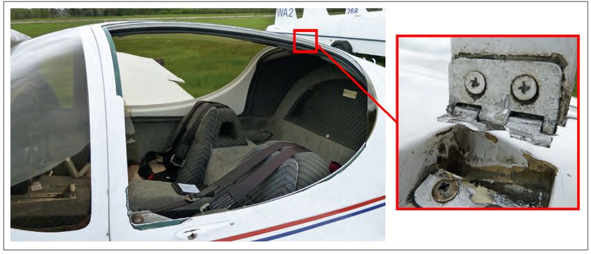
AAIB Special Bulletin: S2/2021                      G-FDZF                                          AAIB-27673

The aircraft was then given a further climb, before being radar vectored for another approach
to Runway 34. The subsequent approach and landing were completed without further
incident.

                                                    Figure 1
                         G-FDZF’s flightpath into Aberdeen and the unintended descent

B737-800 Go Around Mode

The Boeing 737-800 is a dual autopilot, CAT III capable aircraft. Normal procedures, as
outlined by the manufacturer, require the use of a single autopilot on an ILS approach unless
the intention is to conduct a CAT II or III approach and landing. Automatic go‑arounds
are only available from a dual autopilot approach. The autopilot/flight director go-around
mode is engaged by pressing the Takeoff/Go-around (TO/GA) switches. Pressing either
of the switches when the engagement criteria are met will disconnect the single autopilot
(if connected) and place the flight directors in go-around mode. The autothrottle (if engaged)
will move to go-around thrust1, and the flight directors will then command 15º nose-up pitch
until the aircraft reaches a programmed rate of climb. Flight director pitch commands then
target airspeed for each flap setting, based on a maximum takeoff weight calculation.

Recorded data

The aircraft’s Cockpit Voice Recorder had been overwritten because the aircraft remained in
service before the AAIB was notified of the event and the investigation began, but the data

Footnote
1
    Below 2,000 ft radio altitude, one press of a TO/GA switch will cause the autothrottle (if engaged) to advance
    to a power setting for a climb rate between 1,000 and 2,000 ft/min. With two presses of a switch, the
    autothrottle (if engaged) will advance to the full go-around N1 limit. Above 2,000 ft radio altitude, one press
    of a TO/GA switch commands thrust to the full go-around N1 limit (although this is not included in the Flight
    Crew Operating Manual and was unexpected by the crew).

© Crown copyright 2022                                  5                                             All times are UTC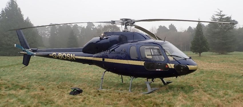
AAIB Special Bulletin: S2/2021                 G-FDZF                                AAIB-27673

from the operator’s flight data monitoring (FDM) provider was available, as well as radar and
R/T recordings from Aberdeen. Figure 2 shows a summary of the FDM data for the approach
and the subsequent unintended descent. The four shaded areas are described below.

                                              Figure 2
                    Flight data for the approach and subsequent unintended descent

Area A shows the flightpath from when the crew responded to the ATC instruction to break
off the approach and shows the disconnection of the autopilot as the TO/GA mode was
activated. It shows that the landing gear was retracted, the thrust increased towards the full
go around N1 limit and the aircraft’s pitch attitude increased as the aircraft climbed. Note
the strong correlation between the changes in the pitch of the aircraft and engine power
setting. No manual pitch trim inputs were observed in the data.

Area B shows that as the aircraft approached the selected altitude of 3,000 ft, the pitch of
the aircraft decreased and the autothrottle reduced the engine power setting in anticipation
of the level-off being commanded by the flight director. As the aircraft reached this point, the
flaps were retracted from flap 15 to flap 5 and the aircraft then descended having failed to
meet the criteria for the flight director to transition to ALT HOLD. The flaps were then further
retracted from flap 5 to flap 1 and from flap 1 to flap 0 during the descent.”

Area C shows the lowest altitude reached by the aircraft before it climbed again, and the
peak airspeed. The climb occurred at about the same time as the crew replied to the ATC
instruction to climb.

Area D shows the autopilot re-engagement and the flight path of the aircraft stabilising.

© Crown copyright 2022                            6                                   All times are UTC
AAIB Special Bulletin: S2/2021 G-FDZF AAIB-27673
Crew recency
The crew of G-FDZF differed in their recency levels but both had experienced significant
periods without flying in the preceding 18 months. The commander had flown 10 flights
during the previous month. For the co-pilot, this was only his fourth flight in nearly 11 months
having completed two flights with a trainer seven days before the day of this incident. Both
pilots had completed numerous simulator sessions during the 18-month period to gain or
retain recency or to complete their annual recurrent check.
Airlines have faced significant challenges in the last 18 months to keep crews current.
Whilst there are legal requirements for crews to complete three takeoffs and landings within
90 days, there are no regulatory requirements laid out for crews to have actually operated
the aircraft, especially on commercial flights. Operators have had to adapt and develop
their own programmes to ensure that crews are prepared and competent to fly, often after
significant periods away from the aircraft.
Simulators have been used not just for the takeoff and landing requirements but also to try
and maintain crew skill levels when operating in both normal and emergency situations.
The challenge has been, and is, to try and represent the real world of flying in a simulated
environment. It can be difficult in the simulated environment to replicate moments of high
crew workload caused by the effects of ATC instructions and background communications,
the presence of other aircraft in the area, poor weather and other operational pressures.
The safety benefits of simulator training are well established. However, the real-world
environment creates different demands on crews, and it is possible that this event illustrates
that lack of recent exposure to the real-world environment can erode crews’ capacity to deal
effectively with those challenges. Regulators have been concerned that pilots returning
to the flight deck following extended periods without flying could be at risk of performing
below their normal standard during their first few flights. Although this investigation has
not established a link between this event and a lack of line flying, this Special Bulletin is
published for awareness and because a link is clearly one possibility.
Other go-around incidents
Two-engine go-arounds can be difficult manoeuvres for crews to fly properly because they
are often unexpected and are only encountered infrequently during line flying and simulator
training. The AAIB has investigated other go-around incidents which have similarities to
G-FDZF1 and the Bureau d’Enquêtes et d’Analyses pour la sécurité de l’aviation civile (BEA)
recently published a report into a similar incident at Paris Orly Airport2.
Footnote
1
Report into the serious incidents involving G-THOF, https://www.gov.uk/aaib-reports/aar-3-2009-boeing-
737-3q8-g-thof-23-september-2007 (accessed November 2021), and I-NEOT, https://www.gov.uk/aaib-
reports/aaib-investigation-to-boeing-737-86n-i-neot (accessed November 2021).
2
https://www.bea.aero/en/investigation-reports/notified-events/detail/serious-incident-to-the-boeing-737-
registered-7t-vjm-operated-by-air-algerie-on-06-12-2019-at-paris-orly/ (accessed November 2021).
© Crown copyright 2022 7 All times are UTCAAIB Special Bulletin: S2/2021 G-FDZF AAIB-27673
Aircraft deviation from the expected flightpath
The aircraft descended from close to 3,000 ft for 57 seconds before a climb was
re‑established, and this represented a significant deviation from the crew’s expected
flightpath. There was a high rate of descent, which was reducing the aircraft’s separation
from terrain, and an uncommanded and undesirable increase in airspeed that were not
corrected in a timely manner.
Further work
The investigation continues to examine all pertinent operational, technical, organisational
and human factors which might have contributed to this serious incident. In particular, work
will be undertaken to:
● Assess the impact of the lack of recent flying on the actions of the crew.
● Assess the effectiveness of the barriers to crews recognising that there has
been a significant deviation from the expected flight path.
● Ensure the flight director behaved as expected.
● Consider the effect of ATC instructions during the go-around and,
subsequently, during periods of high crew workload.
Published: 2 December 2021.
AAIB investigations are conducted in accordance with Annex 13 to the ICAO Convention on International Civil Aviation,
EU Regulation No 996/2010 and The Civil Aviation (Investigation of Air Accidents and Incidents) Regulations 2018.
The sole objective of the investigation of an accident or incident under these Regulations is the prevention of future
accidents and incidents. It is not the purpose of such an investigation to apportion blame or liability.
Accordingly, it is inappropriate that AAIB reports should be used to assign fault or blame or determine liability, since
neither the investigation nor the reporting process has been undertaken for that purpose.
Extracts may be published without specific permission providing that the source is duly acknowledged, the material
is reproduced accurately and is not used in a derogatory manner or in a misleading context.
© Crown copyright 2022 8 All times are UTCAAIB Bulletin: 1/2022
AAIB Field Investigation Reports
A Field Investigation is an independent investigation in which
AAIB investigators collect, record and analyse evidence.
The process may include, attending the scene of the accident
or serious incident; interviewing witnesses;
reviewing documents, procedures and practices;
examining aircraft wreckage or components;
and analysing recorded data.
The investigation, which can take a number of months to complete,
will conclude with a published report.
© Crown copyright 2022 9 All times are UTCAAIB Bulletin: 1/2022 G-BOSN AAIB-27126
SERIOUS INCIDENT
Aircraft Type and Registration: Airbus Helicopters AS355 F1, G-BOSN
No & Type of Engines: 2 Rolls-Royce 250-C20F turboshaft engines
Year of Manufacture: 1982 (Serial no: 5266)
Date & Time (UTC): 2 March 2021 at 1100 hrs
Location: Bourne End, Buckinghamshire
Type of Flight: Commercial Operations
Persons on Board: Crew - 1 Passengers - 1
Injuries: Crew - None Passengers - None
Nature of Damage: Fire damage to right engine cowling and to
engine bay wiring
Commander’s Licence: Commercial Pilot’s Licence (Helicopters)
Commander’s Age: 54 years
Commander’s Flying Experience: 5,150 hours (of which 835 were on type)
Last 90 days – 39 hours
Last 28 days – 20 hours
Information Source: AAIB Field Investigation
Synopsis
Whilst hovering at 20 ft agl smoke was observed coming from the engine exhaust. A
member of the operational team on the ground informed the pilot, who then landed
immediately. A fire warning subsequently illuminated, and the pilot activated the fire
extinguishing system. The fire was determined to have been caused by the loss of
retention of the right engine inboard exhaust nozzle, which was released because of the
failure of its securing clamp. The released nozzle had blocked the overboard exhaust
outlet and allowed hot exhaust gases to impinge on the engine cowlings leading to local
overheating.
The clamp failure was attributed to a combination of an incorrect locking washer being
fitted during maintenance and elevated engine vibration which caused the clamp to loosen.
A crack then propagated in low-load high-cycle fatigue until final rupture of the clamp.
The helicopter manufacturer is taking safety action to amend the Aircraft Maintenance
Manual (AMM) highlighting the correct installation of the clamp.
History of the flight
The helicopter was operating on a film set at Hedsor House having been positioned on
location the previous day. The pilot arrived at the site at 0650 hrs and carried out a
pre‑flight inspection of the helicopter. He then conducted a safety briefing with the Aerial
© Crown copyright 2022 11 All times are UTCAAIB Bulletin: 1/2022 G-BOSN AAIB-27126
Coordinator1 and staff from the production company, the Unmanned Aircraft System (UAS)
operator and the company providing fire cover.
The first sequence of filming required the helicopter to be running on the ground while
an actor approached and boarded through the right door. The pilot started only the left
engine for this task, which lasted approximately 15 minutes and involved several ‘takes’.
Movement around the helicopter was under the control of the Aerial Coordinator and
the pilot who were in radio contact with each other. On conclusion of these takes, the
helicopter was shut down and the pilot and production staff prepared for a sequence of
airborne filming.
The pilot gave a safety briefing to the stunt double who would occupy the left hand seat for
the flight. At approximately 1035 hrs, the pilot started the aircraft and lifted into a 20 ft hover.
After a short period of time, the Aerial Coordinator informed the pilot that smoke was coming
from the rear of the helicopter. The pilot noted that there were no abnormal indications in
the cockpit but decided to make a precautionary landing.
Just prior to the helicopter touching down, the Aerial Coordinator informed the pilot that the
smoke appeared to be getting worse. The pilot continued with the landing and, noting that
the cockpit indications remained normal, shut down both engines. The pilot instructed the
stunt double to exit the helicopter.
Approximately 10 to 15 seconds later the Aerial Coordinator radioed that flames were now
visible at the engine exhaust. As he heard the radio transmission, the pilot noticed the
fire rh warning light illuminate. He pressed the engine fire button, and the fire bottle
discharged its contents into the engine bay extinguishing the flames and the warning light
cleared. The pilot completed the shutdown checks and exited the helicopter. There were
no injuries.
Accident site
Prior to the AAIB arriving on site, the pilot and an engineer from a helicopter maintenance
organisation examined the right engine bay and found that the inboard exhaust nozzle
from the right engine had become detached, and that the clamp that secured the nozzle
to the engine had failed. The detached exhaust nozzle had lodged in the aircraft-mounted
exhaust tube, blocking it. The detached nozzle and the failed clamp were removed from the
aircraft by the maintenance engineer.
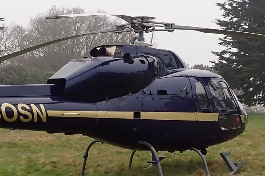
The helicopter, having made a precautionary landing, was positioned on its skids in the
grounds to the south of Hedsor House (Figure 1). Apart from paint blistering of some of the
right engine cowls (Figure 2) and melting of the cowl latches, the external appearance of
the helicopter was unremarkable.
Footnote
1
The Aerial Coordinator provides safety oversight and liaison between the film production company and the
pilot. In this case the Aerial Coordinator was based on the ground.
© Crown copyright 2022 12 All times are UTCAAIB Bulletin: 1/2022 G-BOSN AAIB-27126
Figure 1
G-BOSN after landing
Figure 2
Paint blistering on engine cowling adjacent to right engine inboard exhaust tube
The right engine bay showed signs of elevated temperatures with melting of electrical
connector back shells and harness clipping anti-fret material. The starter generator
overboard duct had also deformed. The condition of the internal panel forward of the
inboard exhaust outlet suggested that the panel had been on fire (Figure 3).
© Crown copyright 2022 13 All times are UTCAAIB Bulletin: 1/2022 G-BOSN AAIB-27126
Figure 3
Evidence of fire damage on engine cowl viewed looking forward through
right inboard airframe mounted exhaust duct
There was no evidence of fire in the left engine bay.
Recorded information
Video footage of the incident flight was made available to the investigation by the production
company. Examination of the footage identified that 30 seconds prior to the helicopter lifting
some smoke was emanating from around the engine exhaust; blistering of the paint on the
upper engine cowl could also be seen. The smoke remained relatively light until the engine
power was increased for takeoff. As it did so, the smoke became more pronounced. The
helicopter was seen to enter a hover and then landed approximately 40 seconds later and
5 m forward from where it had lifted off.
The helicopter did not have either a flight data recorder or a cockpit voice recorder fitted,
nor was it required to have them.
Aircraft information
The AS355F1, ‘Twin Squirrel’, is a twin-engine light utility helicopter developed by Airbus
Helicopters (formerly Aérospatiale), France, in the late 1970s; the F1 variant first being
certified in 1983.
The F1 variant is powered by two Rolls-Royce (formerly Allison) 250-C20F engines, each
mounted to the rear of the main gearbox, side by side, on anti-vibration bases. The engines
are mounted in separate fireproof compartments.
© Crown copyright 2022 14 All times are UTCAAIB Bulletin: 1/2022 G-BOSN AAIB-27126
The engine is an assembly of four modules as follows: the compressor, gearbox, turbine
and combustion modules (Figure 4). Air passes through the compressor and then rearward
via external passageways to the rear of the combustion chamber. The air then enters the
combustion chamber where fuel is introduced and burned. The combustion gases then
move forward through a two-stage gas producer turbine, followed by a two-stage power
turbine. The engine exhaust collector is located to the rear of the gearbox module and
directs the exhaust gases through two exhaust outlets located at approximately 45° either
side of the top of the engine.
Exhaust Combustion
Compressor collector Module
Module
Gearbox
Module Turbine
Module
Figure 4
Rolls-Royce 250-C20F engine airflow schematic (reproduced with permission)
Two exhaust nozzles, supplied by the helicopter manufacturer, are clamped to the engine
exhaust collector outlet flanges (Figure 5). These direct the exhaust gases rearwards.
The inboard nozzle directs its exhaust gases through an airframe mounted exhaust tube,
whereas the outboard nozzle exhausts directly to atmosphere (Figure 6).
© Crown copyright 2022 15 All times are UTCTwo exhaust nozzles, supplied by the helicopter manufacturer, are clamped to the engine
exhaust collector outlet flanges (Figure 5). These direct the exhaust gases rearwards. The
inboard nozzle
AAIB Bulletin: directs its exhaust gases
1/2022 through an airframe mounted exhaust
G-BOSN tube,
AAIB-27126
whereas the outboard nozzle exhausts directly to atmosphere (Figure 6).
Exhaust nozzle
Exhaust nozzle clamp
Engine gearbox
output shaft
Engine mount
Figure
Figure5 5
Rolls-Royce
Rolls-Royce250-C20F
250-C20Fengine
engineinstallation
installation(reproduced with
(reproduced permission)
with permission)
Airframe mounted exhaust tube for
Figure 6 Airframe mounted exhaust tube for
AS355F1
left engine inboard exhaust right engine
showing position of exhaust nozzlesinboard exhaust
Each exhaust nozzle is held in place with a ‘V-band’ clamp (Figure Right
7), which
engineisoutboard
also supplied
exhaust nozzle
by the helicopter manufacturer, incorporating a corrugated “V” mounted on a tightening
band. The band is secured in place with a screw tightened locking mechanism. The
Illustrated Parts Catalogue (IPC) identifies the clamp with part number (p/n) F1N170V and
a locking washer with p/n 350A57-1058-21. The clamp, which is released with a Certificate
of Conformity, is supplied with a serrated locking washer that should be removed and
replaced with the locking washer with p/n 350A57-1058-21. Locking washer p/n 350A57-
1058-21 is not supplied with the clamp and must be ordered separately. Figure 8 shows an
installed clamp with lock washer p/n 350A57-1058-21 fitted. The AMM MET 71-00-00-401
‘Removal – Installation – C20F Allision engine’ paragraph G.2. Installation, when referring
to the installation of the exhaust nozzles, instructs:
Figure6 6
AS355F1 showing position of exhaust nozzles
© Crown copyright 2022 16 All times are UTCAAIB Bulletin: 1/2022 G-BOSN AAIB-27126
Each exhaust nozzle is held in place with a ‘V-band’ clamp (Figure 7), which is also supplied
by the helicopter manufacturer, incorporating a corrugated ‘V’ mounted on a tightening
band. The band is secured in place with a screw tightened locking mechanism. The
Illustrated Parts Catalogue (IPC) identifies the clamp with part number (p/n) F1N170V and a
locking washer with p/n 350A57-1058-21. The clamp, which is released with a Certificate of
Conformity, is supplied with a serrated locking washer that should be removed and replaced
with the locking washer with p/n 350A57-1058-21. Locking washer p/n 350A57-1058-21 is
not supplied with the clamp and must be ordered separately. Figure 8 shows an installed
clamp with lock washer p/n 350A57-1058-21 fitted. The AMM MET 71-00-00-401 ‘Removal
– Installation – C20F Allision engine’ paragraph G.2. Installation, when referring to the
installation of the exhaust nozzles, instructs:
‘(4) Make sure that:
(a) the axis of the exhaust nozzle attachment clamp screw is positioned
at the internal upper part of the engine and is parallel to the engine
axis of symmetry,
(b) the locking washer is installed.’
Locking screw Locking bracket
Originally provided
serrated washer
Tightening band
‘T’ bar
Corrugated ‘V’
Figure 7
As supplied V-band clamp, inset showing serrated washer that must be
removed prior to installation on the helicopter
© Crown copyright 2022 17 All times are UTCAAIB Bulletin: 1/2022 G-BOSN AAIB-27126
Exhaust nozzle
Locking bracket
Locking screw
Lock washer, p/n
350A57-1058-21
to be installed on
the clamp when
fitted
‘T’ bar Engine exhaust
collector outlet
Figure 8
Exhaust nozzle clamp correctly installed
Aircraft maintenance
G-BOSN had recently been subject to a 6 month, 100 hour/12 month, 1,200 hour/28 month
airframe inspection as well as the engines having their 100 hour inspections. At this time
the right engine was removed from the aircraft due to a ‘chip indication’2. The gearbox
and turbine modules were returned to an engine overhaul facility where some gearbox
components were found to have been worn and were determined to be the cause of the chip
indication. The gearbox module was repaired accordingly. Both the turbine and gearbox
modules were returned and refitted to the engine and the engine installed in the helicopter.
When the engine was installed in the helicopter the exhaust nozzles were refitted. This
involved refitting of the exhaust nozzle clamps.
After the right engine had been installed an installation ground run was completed and the
aircraft returned to the operator. The maintenance organisation identified elevated magnetic
chip detector readings, however associated them with the recent maintenance, with no
further action required. This incident occurred 2.6 hours after the engine installation.
Previous clamp failure
Some 335 hours prior to the subject incident, the clamp securing the right engine inboard
exhaust nozzle on G-BOSN failed. This event was not reported by the operator or
maintenance organisation and was therefore not investigated. A replacement clamp was
fitted to the engine on 22 December 2017 and was supplied to the maintenance organisation
with two additional lock washers, p/n 350A57-1058-21. It is likely that the new clamp which
was fitted at this time is the clamp that subsequently failed in this event; as the four clamps
fitted to the aircraft are interchangeable and not traced, it was not possible to verify this.
Footnote
2
This type of engine is fitted with an electronic chip detector. When debris is identified in the engine oil system
a light comes on in the cockpit.
© Crown copyright 2022 18 All times are UTCAAIB Bulletin: 1/2022 G-BOSN AAIB-27126
Aircraft examination
The helicopter was road transported to a helicopter maintenance facility where further
assessment could be carried out. Closer examination of the engine cowling forward of the
inboard exhaust confirmed that a fire had been present and melting of the engine harness
sheathes was also evident. The exhaust clamp was recovered from the maintenance
engineer who had removed it from the aircraft and passed to a metallurgical laboratory for
detailed examination.
Metallurgical assessment of the clamp, p/n F1N170V
Laboratory examination of the clamp identified that the fracture occurred in the tightening
band adjacent to the locking bracket (Figure 9). The fracture surface exhibited features
consistent with low-load high-cycle fatigue crack propagation with the fatigue crack
propagating across 97% of the width of the band. The remaining fracture surface, measuring
approximately 0.5 x 0.5 mm, exhibited features associated with ductile overload (Figure 10)
signifying very low load during the final rupture of the clamp.
Figure 9
Clamp bracket and tightening band showing location of crack initiation
Crack arrest marks
Region of
overload
Figure 10
Tightening band showing area of ductile overload and crack arrest marks
© Crown copyright 2022 19 All times are UTCAAIB Bulletin: 1/2022 G-BOSN AAIB-27126
Assessment of the fatigue surface found that the crack initiated on the edge of the outer
surface of the tightening band, adjacent to the edge of the locking bracket. Mechanical
damage on the outer surface of the band (Figure 11) adjacent to the crack initiation location,
may have acted as a stress concentration for the initiation of the fatigue crack. The cut edge
of the tightening band in this area exhibited features suggesting that it had been guillotined
during manufacture (Figure 12). This unfinished surface may also have influenced the
initiation of the fatigue crack. Significant staining (Figure 13) at the crack initiation location
indicates that the crack may have been present prior to the incident flight. The remainder
of the fracture surface showed consistent colouring with very few crack arrest marks,
indicating that the crack growth was likely to have occurred during recent operation. The
band material was assessed to be consistent with the grade and hardness for the stainless
steel specified by the manufacturer.
Crack initiation Fracture
location surface
Tightening band
outer surface
Mechanical
damage
Figure 11
Edge of tightening band in the location of crack initiation
Fracture
surface
Crack initiation
location
Inner
Outer
Tightening band
cut edge
Figure 12
Edge of tightening band in the location of crack initiation
© Crown copyright 2022 20 All times are UTCAAIB Bulletin: 1/2022 G-BOSN AAIB-27126
Crack initiation
Outer location
Inner
Figure 13
Tightening band fracture surface showing area of crack initiation staining
Examination of the clamp identified that it had been fitted with a serrated locking washer
under the head of the locking screw. This washer was further examined and found to have
evidence of gouging on all serrations and one of the serrated tabs had cracked (Figure 14).
The lock washer, p/n 350A57-1058-21, was not fitted.
Cracked serration
Figure 14
Serrated washer fitted to failed exhaust nozzle clamp
There were no markings on the clamp to confirm part number, batch number or
manufacturing date.
© Crown copyright 2022 21 All times are UTCAAIB Bulletin: 1/2022 G-BOSN AAIB-27126 Other information Post-incident helicopter maintenance A right engine chip caution illuminated during a post-incident maintenance ground run. Further ground running by the maintenance organisation also found an engine was operating close to vibration limits of 1.0 Inches Per Second (IPS) and was therefore rejected. The engine’s gearbox, turbine and compressor modules were returned to the engine overhaul facility for examination. This found that the compressor bearing was in poor condition and was likely to have contributed to the engine chip indication and increased vibration. Observations from helicopter maintenance organisation In comparison to other engine installations on similar helicopter types it was identified that the AMM for the AS355 F1 utilising the Rolls-Royce 250 engine only requires the exhaust nozzle clamp to be torque tightened when it is installed, whereas other installations required exhaust clamps to be re-torqued after the engine had been run. Analysis The investigation confirmed that a fire had occurred in the right engine bay. This was caused by heating of the engine cowling which was due to exhaust gases being directed onto the area. The right engine inboard exhaust nozzle was found to have been released due to the failure of its retaining clamp. It was found to have been blocking the airframe mounted exhaust tube, directing engine exhaust gases back into the engine bay and onto the engine cowling. Laboratory analysis of the retaining clamp found that a crack had propagated across its tightening band in low-load, high-cycle fatigue. It failed in overload when there was an approximate area of 0.25 mm2 of material remaining. The fatigue propagation mechanism and small region of overload fracture on the fracture surface suggests that the failure of the clamp was associated with the clamp becoming loose. The loosened clamp was then able to vibrate, exciting the clamp and allowing the crack to propagate. It is likely that mechanical damage, possibly associated with the clamp manufacture, acted as a stress concentrator, and served to initiate the fatigue crack. The clamp loosening was likely to have been associated with the incorrect locking washer being fitted. The serrated locking washer which was originally supplied with the clamp should have been removed and replaced with a tab locking washer, p/n 350A57‑1058‑21, before fitting the clamp. The condition of the serrated washer indicates that it had been tightened multiple times as the serrations had flattened, and one of the serrations had cracked. This will have reduced its ability to maintain the locking screw in its position. Some 2.6 hours before the incident, the helicopter was subject to routine maintenance inspections. At that time the right engine was removed because of a chip indication and © Crown copyright 2022 22 All times are UTC
AAIB Bulletin: 1/2022                     G-BOSN                                 AAIB-27126

the engine gearbox was repaired due to worn components. Subsequent engine ground
running identified some metal on the magnetic chip detector, which was considered normal
for a recently rebuilt engine, so the engine was released to service. Following rectification
of the fire damage, the engine was reinstalled and generated metal debris during ground
running. When a vibration survey was completed it was found that, whilst the engine
vibration was close to the upper threshold, it remained within the engine manufacturer’s
in-service operating limits. The engine was rejected and investigation by the engine
maintenance organisation found that the compressor module bearings were damaged
and was probably the cause of the chip indications.

With the high engine vibration identified after the incident, it is likely that the engine
would have been vibrating at a similar level during the 2.6 hours between the scheduled
maintenance and the incident.

The combination of the reduced locking capability, due to the multiple re-tightening
against the incorrect washer, and the elevated engine vibration are likely to have caused
the locking screw to have backed off and allowed the clamp to vibrate resulting in its
failure.

The IPC for the helicopter identifies the locking washer part number 350A57-1058-21
as part of the assembly; however, the maintenance manual only instructs to ‘ensure the
locking washer in fitted’. With the clamp being supplied with a locking washer as part of
the assembly, albeit the incorrect one, it is possible that a maintenance engineer could be
satisfied that the correct washer was being used. It is likely that the incorrect washer was
installed when the clamp was originally fitted in 2017 and not noticed to be incorrect when
the clamp was refitted prior to the incident.

Additionally, there is a possibility that the clamp could become loose during the
post‑installation ground run. There was no requirement in the AMM to re-torque the
locking screw after the ground run, but if there had been this may have provided an
additional means to maintain the clamping load on the exhaust nozzle.

Conclusion

The engine bay fire was caused by the loss of retention of the right engine inboard exhaust
nozzle which, when released, blocked the overboard exhaust outlet and allowed exhaust
gases to impinge on the engine cowlings.

Elevated engine vibration, in combination with the fitment of an incorrect locking washer
on the exhaust nozzle clamp screw, was sufficient to allow the screw to back off and
allow the clamp to vibrate. The vibration was sufficient to cause a fatigue crack to
propagate, ultimately causing the clamp to fail and allow the release of the exhaust
nozzle.

© Crown copyright 2022                       23                                    All times are UTC
AAIB Bulletin: 1/2022                         G-BOSN                                AAIB-27126

Safety actions

As a result of this investigation the helicopter manufacturer is taking Safety Actions to
ensure the correct washer is fitted when installing the exhaust nozzles to the engines as
follows:

         The helicopter manufacturer is amending the AMM to clarify the engine exhaust
         nozzles installation working card to:

         ●     Check the condition of the exhaust clamp (absence of cracks, etc.)

         ●     Check if the serrated washer delivered with the clamp is replaced by the
               tab washer

         ●     Introduce an installation drawing depicting the correct installation of the
               clamp and its tab washer

         ●     Check if the tab washer is properly installed and bent according to the
               installation drawing

         ●     After installation, complete a ground run and then re-adjust the tightening
               torque to ensure correct tightness.

Published: 16 December 2021.

© Crown copyright 2022                           24                                   All times are UTC
AAIB Bulletin: 1/2022
AAIB Correspondence Reports
These are reports on accidents and incidents which
were not subject to a Field Investigation.
They are wholly, or largely, based on information
provided by the aircraft commander in an
Aircraft Accident Report Form (AARF)
and in some cases additional information
from other sources.
The accuracy of the information provided cannot be assured.
© Crown copyright 2022 25 All times are UTCAAIB Bulletin: 1/2022 G-EZBD AAIB-27488
SERIOUS INCIDENT
Aircraft Type and Registration: Airbus A319-111, G-EZBD
No & Type of Engines: 2 CFM CFM56-5B5/P turbofan engines
Year of Manufacture: 2006 (Serial no: 2873)
Date & Time (UTC): 13 July 2021 at 1048 hrs
Location: London Luton Airport
Type of Flight: Commercial Air Transport (Non-Revenue)
Persons on Board: Crew - 2 Passengers - None
Injuries: Crew - None Passengers - N/A
Nature of Damage: None
Commander’s Licence: Airline Transport Pilot’s Licence
Commander’s Age: 32 years
Commander’s Flying Experience: 4,412 hours (of which 4,272 were on type)
Last 90 days - 16 hours
Last 28 days - 1 hour
Information Source: Aircraft Accident Report Form submitted by the
pilot
Synopsis
The aircraft carried out a high speed rejected takeoff above V1 speed due to a discrepancy
between the commander and co-pilot’s airspeed indications. The discrepancy occurred
because of a blockage in a pitot tube following a long period on the ground.
History of the flight
The aircraft had last operated a commercial sector on 14 June 2021 when it had flown from
Edinburgh Airport to Luton Airport. The aircraft was then parked at Luton until 13 July 2021,
when it was scheduled for a non-revenue flight after a period of long-term parking.
The pilots were aware that the aircraft had been parked for a protracted period and had
heard of aircraft suffering issues with blocked pitot tubes in similar circumstances. During
their briefing they discussed crosschecking the airspeed indications at 80 kt and emphasised
the need to make any discrepancy of more than 20 kt clear to each other.
The pushback, engine start and taxi out were uneventful and there were no indications of
any instrument malfunctions. The aircraft positioned for a departure from intersection H on
Runway 07 at Luton (Figure 1).
© Crown copyright 2022 27 All times are UTCAAIB Bulletin: 1/2022 G-EZBD AAIB-27488
Figure 1
Luton Airport Diagram
Once lined up on the runway centreline abeam the H holding point, the commander set
50% thrust and stated that the engines took longer to spool up than normal, especially
engine No 1. Once 50% thrust was set, the commander set takeoff thrust and read out the
Flight Mode Annunciators. He noted the aircraft was already travelling at approximately
55 kt before the co-pilot had confirmed the thrust was set. During the acceleration the
co-pilot cross checked his airspeed indications with the Integrated Standby Instrument
system (ISIS), something which the crew had discussed during their briefing. When he
first checked the ISIS it showed approximately 60 kt. He checked the Primary Flight
Display (PFD) and noted it still indicated 40 kt. He immediately rechecked the ISIS and it
had increased to approximately 80 kt. At 80 to 90 kt, the co-pilot told the commander that
his airspeed indication was still reading 40 kt. The commander then checked the co-pilot’s
PFD to confirm that the speed was still at 40 kt and not increasing. The minimum airspeed
indicated on the PFD is 40kt.
The commander glanced outside to check they were still on the centreline and how
much runway remained before checking his own PFD, which was now above 100 kt and
accelerating very quickly. V1 had been calculated as 109 kt so the commander “made a very
quick decision to reject and at V1 called STOP and initiated the rejected take off procedure
moments later”. The RTO was carried out in accordance with SOP, except the co-pilot was
unable to make a call at 70 kt due to his inoperative airspeed indication. The aircraft came
to a stop abeam the A taxiway (Figure 1), approximately 350 m from the end of the runway.
After confirming an evacuation was not required, the aircraft was taxied off the runway and
back to stand.
© Crown copyright 2022 28 All times are UTCAAIB Bulletin: 1/2022 G-EZBD AAIB-27488 Personnel information Both pilots had done relatively little flying in the three months preceding the event. The commander had flown 12 hours 31 minutes in the preceding 90 days and only 37 minutes in the preceding 28 days. The co-pilot had flown 14 hours 45 minutes in the preceding 90 days and 12 hours 31 minutes in the preceding 28 days. The co-pilot stated in interview that he felt the lack of recency had been a factor in the event. The commander, however, felt that the lack of recency had not been a significant issue. Both pilots were aware of an Operational Engineering Bulletin which had been published concerning other blocked pitot events. Recorded information The operator provided the AAIB with a download of the FDR, CVR and Direct Access Recorder. The recorded data showed that after the thrust levers were advanced to the flex position, both engines accelerated symmetrically to the target thrust setting. As the aircraft accelerated, the CVR recorded the co-pilot stating that his airspeed was 40 kt. The takeoff was rejected at an indicated airspeed of 120 kt which was the same as the groundspeed. The aircraft decelerated and came to a halt approximately 350 m from the end of the runway. Operator’s examination of aircraft The aircraft pitot systems were examined after the event and all appeared to be satisfactory. All three pitot systems were flushed in accordance with Aircraft Maintenance Manual (AMM) procedures. During the flush some debris was seen to be removed from the co-pilot’s pitot system. The material was not recovered so the quantity and constituent of the debris could not be determined. Following the flush procedure, all the aircraft pitot systems were leak checked in accordance with AMM procedures and all were satisfactory. The operator had maintenance procedures in place for placing aircraft into long term parking and recovering them from it. The procedures varied dependant on the length of the parking period but all the procedures required that pitot covers be fitted. The aircraft was parked on 14 June 2021 and the ‘Parking Less Than One Month‘ checks were carried out, recording the fitting of pitot covers. The aircraft was then subject to ’7 Day Checks‘ on 21 June 2021, 27 June 2021, 3 July 2021 and 10 July 2021. Each of these required the removal of the pitot covers to allow the aircraft to be ground run and then for the covers to be installed at the end of the check. Aircraft performance The aircraft’s takeoff weight was 41,000 kg, well below the maximum of 66,000 kg. Although the RTO was initiated 11 kt above V1, due to the light weight the aircraft was within the field length limited performance and stopped with 350 m of runway remaining. The flight data was reviewed by the engine manufacturer in light of the flight crew comments regarding engine acceleration. The manufacture concluded that the engine performance was within the expected parameters. © Crown copyright 2022 29 All times are UTC
AAIB Bulletin: 1/2022                         G-EZBD                                  AAIB-27488

Meteorology

The Luton ATIS for the time of the event gave the following weather conditions:

         Wind 360⁰ at 6 kt, visibility greater than 10 km, no significant weather, cloudbase
         3,000 ft agl and temperature 14°C.

Analysis

The aircraft suffered a discrepancy between airspeed systems, which was identified during
the takeoff roll through routine flight crew cross checks. Prior to the flight the crew had
discussed company documentation relating to previous airspeed discrepancy events on
other aircraft and so they were alert to the possibility. The co-pilot noticed a discrepancy
between his PFD and the ISIS at approximately 60 kt. He rechecked the indications and
confirmed that the PFD indications had remained at 40 kt and informed the commander
by which point the ISIS was indicating between 80 and 90 kt. The aircraft was light and
therefore accelerating very rapidly. The commander looked briefly across the cockpit to
confirm the situation and then called “Stop.” The aircraft airspeed was above 100 kt and
increasing rapidly. As a result of the rapid acceleration, by the time the commander was
able to articulate his order, the RTO was initiated at 120 kt, 11 kt above the calculated V1.
However, due to the light weight the aircraft was within the field length limited performance
and stopped safely on the runway.

The debris from the pitot probe was not recovered, so it was not possible to determine the
source of the material that obstructed the co-pilot’s pitot probe. Recorded data showed that
the calculated airspeed on the co-pilot’s system remained at 0 kt throughout the event and
so it is likely that the system was significantly blocked.

The engineering checks carried out on the aircraft before and during the parked period
all recorded that pitot covers were fitted. It was not possible to determine when the pitot
blockage occurred.

Conclusion

The aircraft suffered an airspeed discrepancy resulting from a blocked pitot probe. The
crew recognised the fault and the takeoff was rejected.

© Crown copyright 2022                           30                                    All times are UTC
AAIB Bulletin: 1/2022 EC-MIE AAIB-27402
SERIOUS INCIDENT
Aircraft Type and Registration: Boeing 737-4Y0F, EC-MIE
No & Type of Engines: 2 CFM CFM-56-2CI turbofan engines
Year of Manufacture: 1992 (Serial no: 26069)
Date & Time (UTC): 16 June 2021 at 0104 hrs
Location: East Midlands Airport
Type of Flight: Commercial Air Transport (Cargo)
Persons on Board: Crew - 2 Passengers - None
Injuries: Crew - None Passengers - N/A
Nature of Damage: Damage to towbar and two landing gear tyres
Commander’s Licence: Airline Transport Pilot’s Licence
Commander’s Age: 54 years
Commander’s Flying Experience: 11,750 hours (of which 9,570 were on type)
Last 90 days - 120 hours
Last 28 days - 11 hours
Information Source: Aircraft Accident Report Form submitted by the
pilot and further enquiries by the AAIB
Synopsis
After an uneventful pushback, the towbar was left on the taxiway in front of the aircraft.
Soon after the aircraft commenced taxiing, its left landing gear went over the towbar. The
missing towbar was noticed when the ground crew returned the tug to the towbar parking
area. The aircraft was subsequently stopped from taking off to allow an inspection to take
place. Damage was found to two landing gear tyres, which were replaced before the aircraft
departed.
The investigation found that the ground crew did not complete some of their tasks or check
the taxiway was clear before they left the area.
As a result of this incident the handing agent implemented several safety actions to make
the ground crew’s procedures more robust.
History of the flight
The aircraft was on a cargo flight from East Midlands Airport, Leicestershire, to Vitoria
Airport, Spain. It was parked on Stand 99, on the West Apron. This is a ‘nose-in’ stand
which requires a pushback prior to taxi. The ground crew in attendance for the pushback
were a headset operative (HO) and a tug driver (TD). At the time, it was night.
© Crown copyright 2022 31 All times are UTCYou can also read