BI-FOLD DOOR INSTALLATION MANUAL - Instruction_014 2019-01-16-FFB - Lepage Millwork
←
→
Page content transcription
If your browser does not render page correctly, please read the page content below

BI-FOLD DOOR INSTALLATION MANUAL

Instruction_014                                      2019-01-16 – FFB

Porte Pliante - Bi-Fold Door

CES D'INSTALLATION - INSTALLATION PIECES

                          Description                  Qte / Qty
-

               #10 x 4" washer head screw           En fonction de la
            _____________________________         largeur (1 aux 16'') /
                                                  Depend on the width
                V          e rondelle #10 x 4''
                                                      ( 1 every 16'')

    Si         ssembl / If knock down frame :
                  #6 x 2" flat head screw
              _________________________
                                                            4
                Vis       t te frais e #6 x 2"

                #8 x 3'' washer head screw
              _________________________                    16
                Vis   t       ondelle #8 x 3''
This document will give you step by step instruction to properly install your new Bi-Fold door from
Lepage Millwork. Read the provided instructions in their entirely before starting to install the Bi-Fold Door.
Contact the Lepage Millwork Customer Service Department at 1-800-463-1367 for any question or
clarification.

Any local, regional or national building code requirements supersede these instructions.

If you received the frame knock-down, please refer to Annex B to start.

   1- Insert the frame in the opening and be sure that it is installed square, plumb at level. Lepage Millwork
      has supplied 4’’ (100mm) screws to support the head jamb. The screws provided are only a suggested
      screw size and the actual screw size that will be needed must be long enough to penetrate at least
      2’’ (50mm) into the header. The top track is pre-drilled; install a screw in each hole. It is very
      important that the head jamb is shimmed and properly anchored to the header. The weight of all
      the door panels will be held by the head jamb and if it is not anchored properly the installation will
      fail. It is very important that the head jamb be shimmed and anchored to the header as straight as
      possible. Any bow in the head jamb could cause problems with the operation of the door, but a 1/8’’
      bow or less in an upward position will be acceptable, but never bow in the down position.
                                                                                        Mur / Wall

Instruction_014                                2019-01-16 – FFB                                      1/5
2- Install all panels in numerical order per the Annex A. All panels are pre-drilled for the hinges. If you
      have aluminum clad panels, be sure to install the outer screws through the hinge into the wood first.
      Then install the screws through the hinge into the aluminum next to ensure that the hinge is level.

           a. For the middle hinge on the frame, use “ L “ pin as per illustration below.

Instruction_014                               2019-01-16 – FFB                                  2/5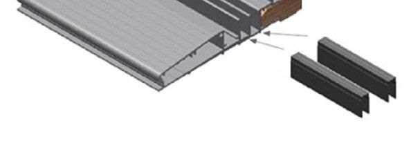
3- Door adjustment. Nominal* gap :

           a. 9/32’’ (7 mm) between 1st door and frame. **

           b. 3/16’’ (5 mm) between the top of the panel and the head frame.

           c. 3/16’’ (5 mm) between active and inactive door.

           * This is a suggested gap, depending of the installation environment, the size of the gap may varie.

           ** For the 2L, 2R, 2L2R. 4L, 4R. 4L4R, 6L and 6R configurations, the gap is ½” (12mm) on the
           opening side.

Side adjustment:

Instruction_014                                2019-01-16 – FFB                                  3/5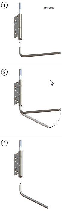
Height adjustment:

Depending of your hardware type:

Model with flat screwdriver:

Model with Allen key:

       1) Insert the Allen key at the bottom of the hinge

       2) Turn right or left to move up or down the panel

       3) When the panel is set to the correct height,

           remove the Allen key to secure the panel

Instruction_014                              2019-01-16 – FFB   4/5
4- Snap in cover for flushbolt channels to prevent accumulation of debris at sill and head (optional).
This PVC cover for flushbolt channels are delivering with the same length as sill and
head.
Field installation, after doors assembly, cut and install one section between each
locking points. Keep around 1’’ between each sections.
5- Install the handle
Specific Bi-Fold hardware care and maintenance1 :
- Always keep the sill clean and the head track clear of debris to ensure proper bearing. Occasionally
lubricate the bearings at the head and the hinges.
1
See installation manuel and maintenance of Lepage Millwork products for more details.
Instruction_014 2019-01-16 – FFB 5/5ANNEXE - B -
1 - Apply exterior grade glue at each corner before screwing them together (in the pre-drilled hole). Use #8 x 3'' screw
on the top of the head and on the side of jamb with the sill
2 - Use #6 x 2 '' on the side of the jamb and the head.
2.5 - If this Bi-fold door has cladding, apply the sealant in the corners then, use the #6 x 1" screws to tighten.
3 - Make a joint on the sill at each corners.
__________________________________________________________
1 - Appliquer de la colle (pour application ex rieure) dans les coins avant de les visser (avec les trous pr -per s) .
Utiliser des
vis #8 x 3'' pour le dessus de e ainsi que le du jambage se vissant dans le seuil.
2 - Utiliser des vis #6 x 2'' pour visser le du jambage te.
2.5 - Si ce produit est recouvert, appliquer le scellant dans les coins et visser une vis #6 x 1".
1
3 - Faire un joint de scellant au seuil la dans les coins.
Colle / Glue
2
2.5
1
Scellant / Sealant
Joint de scellant / Scellant joint
Projet: Dessin par:
Assemblage Cadre / Frame plbell
Cr er le: Mise jour:
2014-06-23
Description:
assembly Num o:
2014-06-23
Recouverte / Clading Cadre / Frame assembly Instruction 014You can also read